background image

EZT-550 Controller Manual


47

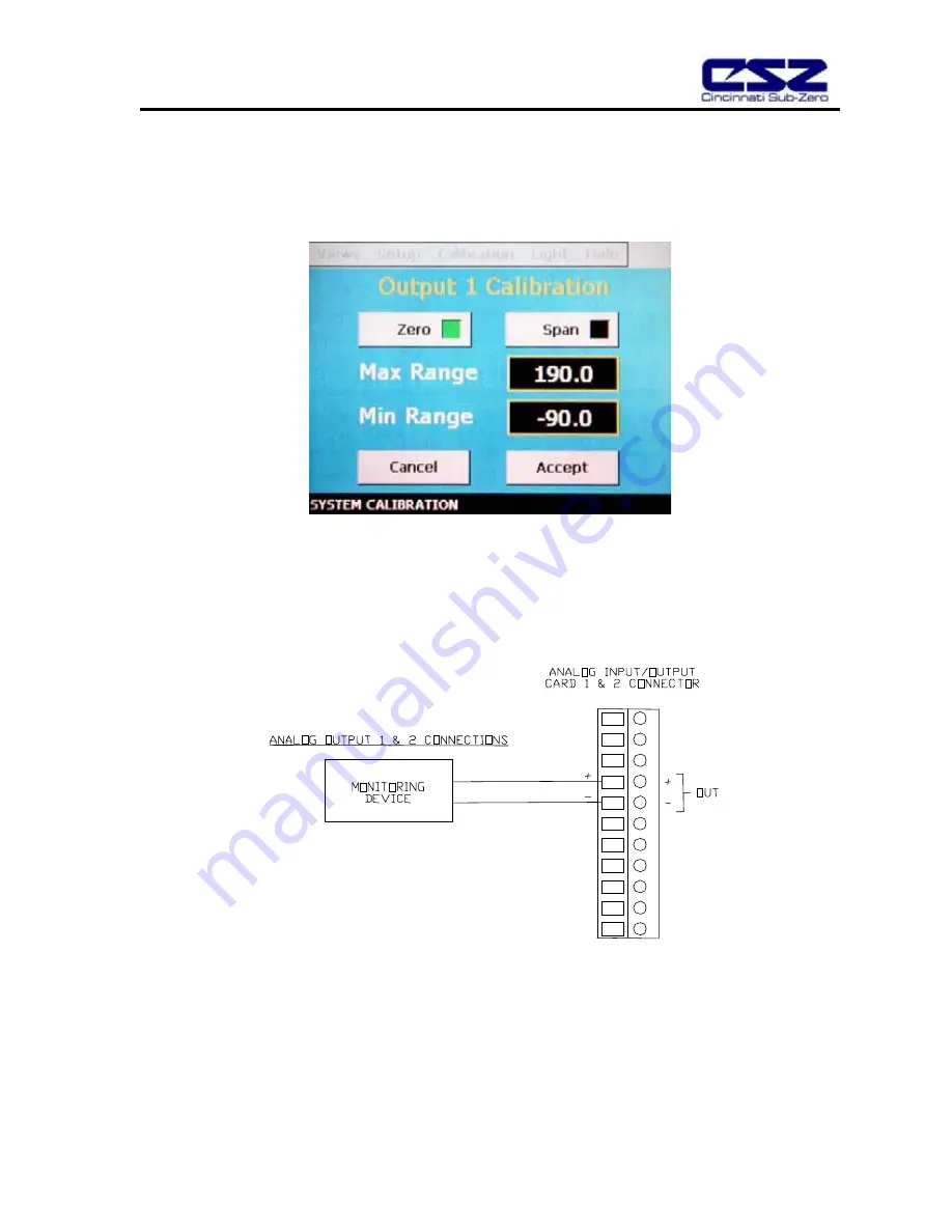
How to Calibrate Analog Outputs 1 and 2  (Air Temperature and Relative Humidity Retransmit) 

1)  Select Analog Output 1 or 2 from the Calibration menu.  The calibration window for the output will 

appear showing the minimum and maximum range settings. 

2)  Set the minimum and maximum range values to the desired range for the output by touching the field 

entry box and entering the value via the pop-up keypad. 

3)  Connect the output to a chart recorder or other instrument that is being used to monitor the output. 

4)  Press the Zero button to retransmit the minimum output value.  Adjust the input of the chart recorder, or 

other instrument connected to the output, to read the minimum range value. 

5)  Press the Span button to retransmit the maximum output value.  Adjust the input of the chart recorder, 

or other instrument connected to the output, to read the maximum range value. 

6)  Once all adjustments are made, press the Accept button to save the changes.  To exit without saving 

changes, press the Cancel button. 

Содержание EZT-550

Страница 1: ...EZT 550 Controller Instruction Manual 56121 REV B 8 05 ...

Страница 2: ...ile 22 4 4 Start Stop Profile 23 4 4 1 Hold Resume a Profile 24 4 4 2 Advance Previous Next Step 24 5 Chamber Setup 25 5 1 Control Tuning 25 5 1 1 How to Adjust Tuning Parameters 27 5 2 Device Under Test DUT 28 5 3 Event Tag Names 29 5 4 Power Recovery 30 5 5 Timer Setup 31 5 6 Defrost Settings 33 6 Datalogging 34 6 1 Start Stop Datalogging 34 6 2 View Log File 35 6 2 1 Deleting Log Files 38 7 Sys...

Страница 3: ... 1 Connecting a Computer to the EZT 550 53 9 1 1 RS 232 Serial Connection 53 9 2 Maintenance Protocol 54 9 2 1 Write Data Command 55 9 2 2 Read Data Command 57 9 2 3 BCC Block Check Calculation 58 9 3 EZT 550 Operands 59 9 3 1 Profile Area Operands 63 ...

Страница 4: ...and or safety devices These devices are installed to protect the chamber from exceeding design limits These devices remove power from the chamber s heaters ONLY and DO NOT remove power from the device under test Provisions must be made by the end user to de energize the tested device in the event of an over temperature condition For this reason the chamber is equipped with a DUT safety relay that ...

Страница 5: ...go multiple levels deep in screens like other button style systems The EZT 550 provides a Windows like feel with drop down menus and online help at all times This section of the manual provides an overview of the menu items and structure 1 1 Menu Bar Function Tree The menu structure for the EZT 550 is as shown below Main Menu Views Chamber Monitor Chamber Detail Chamber Trend Graphic Monitor Syste...

Страница 6: ...rol Tuning DUT Settings Event Tagnames Power Recovery Timer Setup Defrost Settings System Maintenance Setup Chamber System Maintenance Views Chamber Setup Setup Degrees C F Maintenance Counters Password Entry Setpoint Limits Set Date Time Startup Configuration Calibration Analog Input 1 Analog Input 2 Analog Input 3 Analog Input 4 Analog Out 1 Analog Out 2 ...

Страница 7: ...lay Area The main display area contains the active items for the menu item selected Detail Window The detail window provides display specific information To select items on the display simply touch the desired text or numerical entry item Do not use any sharp or metal objects on the touch screen as they will damage the interface For detailed information regarding the different screen elements see ...

Страница 8: ...itor The monitor screen displays the current setpoints and process variables The setpoints can be modified from this screen by touching the setpoint field box Upon pressing the setpoint field box the pop up numeric entry pad will appear from which the setpoint can be entered However if a profile is running or the timer is enabled the setpoint fields are locked out from user adjustment Process Vari...

Страница 9: ...essed in terms of percent The display range is from 100 to 100 representing full cooling to full heating for example A reading of zero means that no cooling or heating is being performed Event Table The events are used to control specific chamber functions and optional customer relays Not all events are used with the ZP H Series chamber and are marked as such The scroll bar to the right of the lis...

Страница 10: ...guration To adjust the displayed variables range and sampling period touch the Trend Setup button The Trend Setup screen will appear with the available adjustment controls Trend Zero The zero value sets the minimum range of the vertical access for the trend variables Trend Span The span value sets the maximum range of the vertical access for the trend variables Time Mins The time interval is in mi...

Страница 11: ...when the Cancel button is pressed will be disregarded 2 4 Graphic Monitor The graphic monitor displays the process variables using graphic symbols i e thermometer for temperature for example The range of the thermometer can be changed by touching the thermometer Low and high range adjustment boxes appear at the bottom of the screen After changing the range s touch the thermometer again to accept t...

Страница 12: ...he profile status view contains information on the current profile in operation It is accessed under the profile sub menu To view the screen from the main menu select Profile Edit Monitor Views Profile Status View 1 Profile Name Displays the name of the profile being run 2 Current Profile Status Displays the current operating status of the selected profile 3 Temp Displays the current temperature i...

Страница 13: ...nning Displays the total time the profile has ran in hours and minutes This includes total step times and time spent in hold 12 Cur Recycle Step Indicates the current step number that the profile will jump to when the current step is complete and when recycle count see below is greater than 0 A step number of 0 indicates that no jump will take place 13 Recycle Steps Left Indicates how many jumps a...

Страница 14: ...adjust the setpoint 1 Select either the Chamber Monitor or Chamber Detail screen under the Views menu 2 Input the setpoint temperature humidity Press the setpoint SP field box for temperature and or humidity The setpoint adjust keypad will pop up on the screen Enter the desired setpoint value and press the Done button 3 Turn the Chamber event on see section 3 2 below ...

Страница 15: ...ive humidity is still measured and displayed however no control takes place to obtain the target setpoint NOTES on humidity system operation Temperature Extremes When operating your environmental chamber at extreme air temperature setpoints below freezing 0 C 32 F or above boiling 100 C 212 F the chamber is not capable of controlling humidity This is due to the physical properties of air and its a...

Страница 16: ...e It is an inexpensive method for fast cooling transitions without having to make the investment in a high horsepower refrigeration system that may rarely be used When this option is installed on the chamber turn the Aux Cooling event on When the boost is required during a pulldown the EZT 550 will turn on the boost cooling solenoids and inject LN2 or CO2 into the chamber to drop the temperature a...

Страница 17: ...ogrammatically through a running profile You can use them to start and stop devices under test within the chamber turn signal beacon lights on and off to indicate steps within the test cycle etc CAUTION The relay outputs are rated for 125Vac and up to 2A of current To switch high power loads the event relay must be used as the switch to turn a power contactor on and off to supply power to the test...

Страница 18: ...dit Profiles are created edited from the Profile Entry screen located under the Profile menu selection The following instructions describe the steps involved for programming profiles 1 To create a profile go to the Profile Entry screen This screen appears by default upon selecting Edit Monitor from the main Profile menu The profile entry screen can also we selected at any time from the profile Vie...

Страница 19: ...d step data to current step Select Profile Opens the file explorer window so that the user can select a profile from the currently saved profiles Save Profile Saves any changes made to the current profile under the existing name If no name exists the user is prompted to enter one Save As Allows the user to save the current profile to a different name This is useful for copying profiles in order to...

Страница 20: ...n Note This must be done for each step individually Also for the chamber to operate the relevant chamber systems must be turned on via the event entry window Even though a profile may be in operation if the events are not set the chamber will not run TempSP Target setpoint for air temperature during execution of step RHSP Target setpoint for humidity during execution of step Hrs and Mins Time leng...

Страница 21: ...to save the profile On the save profile window touch the Filename entry field An alphanumeric keypad will appear Enter in the desired filename for the profile and press Done The keypad window will close and return you to the save profile window If the filename entry is correct press the Save button The profile is now saved in memory ...

Страница 22: ... a band limit too tight could prevent the profile from operating correctly because the chamber may not be able to control to such a tight band setting A typical band setting would be 1 C 1 8 F for temperature and 4 for humidity The soak limits are saved with the current profile When changing the soak band settings be sure to save the profile in order to update the profile with the new settings Thi...

Страница 23: ...his allows you to see if the profile you programmed matches the desired profile To plot the profile select Plot Profile from the Views menu under Profiles Press the Plot button on the upper right of the screen The EZT 550 will then generate a graphical representation of your profile Note The Y axis auto scales to fit the setpoints within the profile The X axis auto scales to the number of steps in...

Страница 24: ...ow will appear prompting you to enter the step number for which the profile is to start on The default is step 1 Use the scroll buttons to adjust the start step if required and press the Start Profile button The profile will then be loaded into memory and started once the load is complete The profile status screen will automatically appear upon starting the profile so that the profiles operation c...

Страница 25: ...eration in this manner from the point that power was lost if the power recovery feature is enabled See section 5 4 for more information regarding power recovery options 4 4 2 Advance Previous Next Step The advance step function allows the user to skip certain profile steps or repeat them by advancing to the desired step To advance to a previous or next step in the profile the profile must be first...

Страница 26: ...set by the factory at optimal settings for the chamber Under most circumstances these values should not require modification However under certain conditions these values may have to be changed to compensate for live loads etc Prior to altering these values be sure to read Section 5 1 1 to get an understanding of how each setting affects control response To view and or adjust tuning parameters sel...

Страница 27: ...t periodically The reset value specifies the time interval between output additions Note When the integral time is too short the integral action becomes large resulting in an overshoot of a long period In contrast when the integral time is too long it takes a long time for the process variable to reach setpoint Rate derivative action Rate is a function to adjust the output in response to a disturb...

Страница 28: ... Typical values are between 5 00 and 10 00 6 A typical setting for the rate will be approximately 0 4 of the reset value 7 Verify operation of the chamber at the desired points Some minimal adjustments may be needed for specific points Humidity 1 Set up your test load and turn any live loads on 2 Set the setpoint for ambient 24C 75F and the humidity for 50 This is the most difficult humidity contr...

Страница 29: ... the chamber to restart the temperature of the product must re enter the safe range Notes on using the product safety CAUTION In order for the product safety to work correctly you must place the DUT temperature sensor on your product so that it can sense the temperature CAUTION The DUT safety connection on the chamber is provided as an interface to your product s power controller The connection is...

Страница 30: ...ION When cascade control is enabled the air temperature will exceed setpoint in order to get the product to temperature as quickly as possible The DUT high and low limits become the maximum and minimum achievable air temperatures Be sure that your product will not be damaged by exposure to these air temperatures during transitions prior to enabling cascade control 5 3 Event Tag Names The names of ...

Страница 31: ...profile will also be stopped Hold Select hold to have the chamber return to operation at the same point it was prior to the power outage If a profile was running the profile will still be active however it will remain in hold until manually set to continue Continue Select continue to have the chamber pick up where it left off on loss of power If a profile was running prior to the power outage it w...

Страница 32: ...cess the timer select Timer Setup from the Setup menu 1 Begin by setting the timer mode of operation Press the Mode Setup button to access the timer mode settings screen Timer Type The timer type selection determines what function the timer is to perform Constant SP Operates the chamber at the current setpoint entered for temperature humidity prior to turning on the timer Profile Starts the last p...

Страница 33: ... return to the main timer screen If the Close button is pressed prior to accepting any changes the changes will be lost 2 If the timer type is set to profile then skip to step 3 If the timer type is set to constant then the events must be set as required To set the appropriate events press the Event Selection button to access the Timer Events screen Select which of the chamber systems and events y...

Страница 34: ...tarted it will run until complete or stopped by the user 4 Once all settings have been made press the Timer On Off button When the timer is off the button will read Timer Off and the green indicator light will be off When the timer is enabled the button will read Timer On and the green indicator light will illuminate Note When the timer is enabled the timer will assume control of the chamber from ...

Страница 35: ... fixed 1 minute interval to the memory stick Note that the memory stick must be installed or the data logging function will be inoperative Logging On Off When logging is on the EZT 550 continuously logs data around the clock The data is stored to files named with the date time that the file was created Thus at midnight each day a new file is created with that day s date and time at which it was st...

Страница 36: ...rofile run Log Filename Prefix The file name prefix is a description you can set to identify the log files easily in response to an operational period profile run etc To set the prefix data logging must be turned off Set the prefix by touching the filename field A keypad will appear allowing you to enter the prefix Once the prefix is set turn logging back on by selecting the desired logging option...

Страница 37: ...e time in hours and minutes for the start and stop of the plot This allows sections of the file to be viewed for zooming in on certain areas The file start and stop dates and times are provided for reference when setting the time period of the trend The time period defaults to the span of each history file when they are opened 3 Select History Plot Channel Setup from the Datalogging menu to config...

Страница 38: ...e Clear All button to remove the current selections Select the desired point and color for the point via the drop down selection boxes and press the Add Point button 4 Once the setup is complete select Plot History Data from the Datlogging menu The EZT 550 will plot the data according to the previously selected setup This may take up to 10 seconds depending on plot size 5 Press Done when finished ...

Страница 39: ... Data files can be deleted one at a time by selecting Delete Data File from the Datalogging menu The previously opened data file is then deleted from the memory stick Note to delete more than one file each file must be individually opened and then deleted ...

Страница 40: ...entering system maintenance all automatic chamber operations must be stopped This includes data logging profiles and timer operation Upon selecting system maintenance a pop up window will alert the user that the chamber will be taken off line The user can select No to return to the chamber setup menu without shutting down any current operations If the user selects Yes all operating systems of the ...

Страница 41: ... time have been accepted Press OK to close the message window Notes on clock operation Time set The time is set in 24 hour military time The day of week must be set correctly in order for the day by day timer to function correctly Battery back up The clock is battery backed for a period of approximately 30 days If power is removed from the chamber for more than 30 days the clock will have to be re...

Страница 42: ... disabled menu items will be activated If the password is incorrect a message box will appear to notify the user of an incorrect password See Appendix A of this manual for your passcode 7 2 1 Degrees C F Selection The EZT 550 can display temperatures in either degrees C or F To change the units select Degrees C F from the setup menu Press the appropriate button to select the desired units A messag...

Страница 43: ...intenance Counters from the setup menu The maintenance counters provide hours of operation monitoring for items such as air circulators and compressors as well as cycle counts for solenoids number of starts for compressors etc The service interval is fixed at the factory for each component based on the required service interval To clear a counter select the counter by touching the related componen...

Страница 44: ...ve no affect on the operation of the chamber The three analog inputs are configured as follows Analog Input 1 Air Temperature Input Type RTD Input Range 100 C 148 F to 500 C 932 F Accuracy 0 2 of full scale LSB 1 35 C 2 43 F Analog Input 2 Device Under Test DUT Temperature Input Type RTD Input Range 100 C 148 F to 500 C 932 F Accuracy 0 2 of full scale LSB 1 35 C 2 43 F Analog Input 3 Humidity ZPH...

Страница 45: ...rom the analog input on analog input card 1 The input card is connected to the CPU module on the electrical sub panel located beneath the chamber door behind the front cover Note Analog input output card 2 and the digital output card may not be present on all chambers They are installed based on options provided with the chamber 3 Connect the leads from the calibration source to the input terminal...

Страница 46: ...EZT 550 Controller Manual 45 ...

Страница 47: ...eference value to the range value to correct for any offset in the input circuit 5 Once all adjustments are made disconnect the calibration source from the input and reconnect the sensor leads Verify that the input reads correctly 6 After verifying that the input reads correctly press the Accept button to save the changes Upon accepting the changes the calibration window will close To exit without...

Страница 48: ...a the pop up keypad 3 Connect the output to a chart recorder or other instrument that is being used to monitor the output 4 Press the Zero button to retransmit the minimum output value Adjust the input of the chart recorder or other instrument connected to the output to read the minimum range value 5 Press the Span button to retransmit the maximum output value Adjust the input of the chart recorde...

Страница 49: ... fields on the display The calibration utility is provided in order to readjust the screen when this happens Note Even after calibration some fields may require finesse to operate Check boxes require precise presses even when the screen is in full calibration Most response issues result from fat fingering the display Use the tip of your finger or a stylus if necessary to operate the unit To access...

Страница 50: ...art the calibration utility Crosshairs will appear on the screen At each crosshair position touch the screen to set the calibration position The calibration requires five points the center and four corners Once complete the calibration utility will exit and return to the System settings window ...

Страница 51: ... for Cincinnati Sub Zero personnel and its affiliates These settings affect chamber operations and safeties and are not meant for the end user Any modification of these settings without written authorization from Cincinnati Sub Zero will void the chamber warranty 7 3 1 Setpoint Limits The setpoint limits restrict the minimum and maximum setpoints for temperature and humidity that can be entered Th...

Страница 52: ...letter to it Access the memory stick just like you would your computer s hard drive 8 1 Opening Files The memory stick will contain a file directory called Data Files Open the Data Files directory to view the available historical log files The data files are stored in csv format The data files can be opened by any spreadsheet program such as Microsoft Excel It is recommended that the data files be...

Страница 53: ...al 52 Once opened the log file will display columns of data including the date time and corresponding process variable and setpoint values The data can then be manipulated and graphed if desired using your spreadsheet program ...

Страница 54: ...igned to allow two computers to communicate with each other via their serial ports This cable differs from that of a standard cable in the fact that the transmit and receive wires are reversed If one is not available a cable can be fashioned rather easily Use a high quality shielded cable and connect the leads as shown below Chamber Serial Connection Computer Serial Connection Description Pin Pin ...

Страница 55: ... sent from the computer to write data to read or clear data from the EZT 550U The reply message is sent from the EZT 550 in response to the request message from the computer Communications is always initiated by the computer by sending a request message to the EZT 550 which then returns a reply message to the computer The EZT 550 cannot initiate communications in the computer link system Computer ...

Страница 56: ...ection 9 2 3 for BCC calculation Data Format in the Request Message Write Data Command In order to properly insert the required fields into the request message the values must be properly converted into ASCII codes In the following example a decimal data value of 40966 is to be written to an operand in the EZT 550 Bit 15 Bit 0 The value consists of two bytes upper and lower First convert the decim...

Страница 57: ... Data Command If the request message was valid the EZT 550 will send an OK reply to acknowledge the data write If the message was formatted of received incorrectly the EZT 550 will send an NG reply to notify the user that the command was not processed ...

Страница 58: ...d to read process variables setpoints and chamber status Request Message Read Data Command NOTES 2 Communication device number is always 00 30h 30h 5 Data type designation is D 44h 6 See Section 9 3 for operand designations 7 Data length varies upon number of operands read Each operand consists of 2 bytes 8 See Section 9 2 3 for BCC calculation Reply Messages Read Data Command ...

Страница 59: ...l value of 708 9 2 3 BCC Block Check Calculation For both the write and read commands the BCC must be calculated and inserted into the command The BCC is used by the EZT 550 to make sure that the command sent was the command received It does this by calculating the BCC of the received command and comparing it to the BCC sent in the command to verify that the received data is correct and has not be...

Страница 60: ...ing events each bit must be set every time the operand is written to in order to keep the event on Example Turn on chamber and humidity system Set bits 0 1 decimal 3 Turn off humidity system only Set bit 0 on only decimal 1 0003 Customer Events Used to turn optional customer event relays on and off Read Write set bit on to turn on event Bit 0 Customer Event 1 Bit 1 Customer Event 2 Bit 2 Customer ...

Страница 61: ... decimal point is implied as the first digit in the data value Example Data value read of 997 99 7 0017 DUT Product Temperature Read Only Range range of chamber Note The process variable is read in whole numbers The decimal point is implied as the first digit in the data value Example Data value read of 250 25 0 0018 Relative Humidity Read Only Range 0 100 Note The process variable is read in whol...

Страница 62: ... 1 Pressure switch safety tripped 4 Discharge temperature thermostat tripped 0057 Humidity System Status Indicates humidity system trouble Read Only Bit 0 Humidity system disable air temperature out of range Bit 1 Boiler over temperature Bit 3 Boiler water level low Bit 4 Reservoir level low when optional reservoir installed Note The alerts are bit oriented in the operand The actual value of the o...

Страница 63: ...o 80 C 112 F to 200 C 392 F See chamber manual to verify valid safe operating range Note The setpoint must be in whole numbers The decimal point is implied as the first digit in the data value Example Setpoint of 42 4 C 424 sent to operand 0144 Product Low Limit Sets low alarm point for DUT protection Read Write Typically limited to 80 C 112 F to 200 C 392 F See chamber manual to verify valid safe...

Страница 64: ...nteed Soak Band This operand must be set for the deviation band temperature desired if guaranteed soak is being used Read Write Range temperature range Note The setpoint must be in whole numbers The decimal point is implied as the first digit in the data value Example Setpoint of 0 5 C 5 sent to operand 3002 Humidity Guaranteed Soak Band This operand must be set for the deviation band humidity des...

Страница 65: ... operand is used to turn the chamber systems on off as required in the step of the profile Read Write set bit on to turn on event Bit 0 Chamber On off Bit 1 Humidity System On off Bit 2 Auxiliary Cooling On Off Bit 3 Dry Air Purge On Off 3012 Customer Events Used to turn optional customer event relays on and off as required in the step of the profile Read Write set bit on to turn on event Bit 0 Cu...

Страница 66: ... Read Write Limited to temperature range of chamber Typically 73 C 100 F to 190 C 374 F See chamber manual to verify valid safe operating range Note The setpoint must be in whole numbers The decimal point is implied as the first digit in the data value Example Setpoint of 42 4 C 424 sent to operand 3017 Not Used on ZP H Series Not Used on ZP H Series Once all of the steps are loaded The profile ca...

Страница 67: ...s 0047 Total Run Hours of Current Profile Contains the number of hours the current profile has run Read Only Range is 0 to 32767 hours 0048 Total Run Minutes of Current Profile Contains the number of minutes the current profile has run Read Only Range is 0 to 59 minutes 0049 Current Step in Profile Contains current step profile is running Read Only Range is limited to last step of loaded profile 0...

Страница 68: ...ual 67 Appendix A The passcode for System Maintenance is 40104 It is recommended that this sheet be removed from the manual and stored in a safe location to prevent unauthorized personnel from accessing the maintenance area ...

Страница 69: ...EZT 550 Controller Manual 68 Appendix B ...

Отзывы: