CrustBuster 3200 Скачать руководство пользователя страница 2

Identification

Your CrustBuster® drill is identified by a Serial Number and Model Number.  Record
these numbers in the spaces provided in this manual and refer to them when ordering
parts or requesting service.

Serial Number

Model Number

Warranty

WARRANTY

:  In  addition  to  the  implied  warranties  of  fitness  and  of  merchantability,

CrustBuster®/Speed King, Inc. warrants new products sold by it to be free from defects in
workmanship and material for a period of 12 months, from the date of delivery to the first user
customer. Warranty on purchased parts (cylinder, blades, bearings, shanks, etc.) will be the
same as that offered by the appropriate manufacturer of these parts.

EXCLUSIONS

:  No  warranty  of  any  kind  is  made  by  CrustBuster®/Speed  King,  Inc.  with

regard to new products which have been subject to operation in excess of recommended
capacities, misuse, abuse, negligence, or accident, or have been altered or repaired in any
manner not authorized by CrustBuster®/Speed King, Inc. CrustBuster®/Speed King, Inc. is
constantly striving to improve its products. Changes in design and improvement will be made
whenever  CrustBuster®/Speed  King,  Inc.  believes  the  efficiency  of  its  products  will  be
improved thereby, but without incurring any obligation to incorporate such improvements in
any  products  which  have  been  shipped  or  are  in  service.  No  obligation  exists  for
compensation of unauthorized repairs or modifications without prior approval. And in no event
will CrustBuster®/Speed King, Inc. be liable for consequential damages, such as but not
limited to: downtime, delayed or late tillage or planting, etc.

WARRANTY  REGISTRATION

:  This  warranty  is  not  valid  unless  registered  with

CrustBuster®/Speed  King,  Inc.  within  10  days  from  the  date  of  purchase.  It  is  the  sole
responsibility of the selling retail dealer to fill out the registration forms and see that they are
properly filed with CrustBuster®/Speed King, Inc.

WARRANTY  PROCEDURE

:  Should  any  part  fail  to  conform  with  this  warranty,

CrustBuster®/Speed King, Inc. will repair or replace the part or parts which do not conform.
If  a  part  is  defective,  take  it  to  your  authorized  CrustBuster®  Farm  Equipment  Dealer
immediately, along with your warranty registration, and complete the proper forms requesting
a warranty adjustment. Our representative will pick up the part to be returned to the factory
for examination. If the customer (first user) requests that a new part be substituted for the old
part, a new part will be charged to the dealer who will in turn charge the customer. If the part
is found by us to be defective, a credit for the part will be given to the dealer to be passed on
to the customer. If the dealer or customer wishes to repair the part, this will be done only if
authorized by CrustBuster®/Speed King, Inc. This warranty procedure is in addition to all
remedies authorized by law.

CRUSTBUSTER®/SPEED KING, INC.
Box 1438
Dodge City, KS 67801

       Specifications are subject to change without notice.                        

       ®

  is a registered trademark of CrustBuster/Speed King, Inc.

Содержание 3200

Страница 1: ...3200 Trash Shank OWNER S MANUAL 01 10 601401 ...

Страница 2: ...ifications without prior approval And in no event will CrustBuster Speed King Inc be liable for consequential damages such as but not limited to downtime delayed or late tillage or planting etc WARRANTY REGISTRATION This warranty is not valid unless registered with CrustBuster Speed King Inc within 10 days from the date of purchase It is the sole responsibility of the selling retail dealer to fill...

Страница 3: ...r Parts 32 A Frame 32 33 40 A Frame 34 35 Frame Sections 32 40 Center 36 37 32 Left Wing 38 39 32 Right Wing 40 41 40 Left Wing 42 43 40 Right Wing 44 45 Drive Assemblies Center 46 47 Left 48 49 Right 50 51 Box Assembly 52 53 Hitch 54 Wing Carrier 55 Top Bottom Slide Assembly 56 Presswheel Spring Assembly 56 Presswheel Assembly 57 Trash Shank Tooth Assemblies 58 59 Trash Shank Tooth Hoses 59 Hydra...

Страница 4: ...e It Is In Motion To Our Customers The following pages and illustrations are printed to help supply you with the knowledge to better operate and service your new CrustBuster equipment We are proud to have you as a customer and feel you will be proud to be a CrustBuster owner Any piece of equipment needs and must have a certain amount of service and main tenance to keep it in top running condition ...

Страница 5: ...Safety RECOGNIZE SAFETY INFORMATION UNDERSTAND SIGNAL WORDS FOLLOW SAFETY INSTRUCTIONS 3 ...

Страница 6: ...Safety OPERATE SAFELY AVOID TIP OVERS KEEP RIDERS OFF MACHINE 4 ...

Страница 7: ...Safety HANDLE FUEL SAFELY AVOID FIRES PREPARE FOR EMERGENCIES WEAR PROTECTIVE CLOTHING 5 ...

Страница 8: ...Safety USE SAFETY LIGHTS AND DEVICES TRANSPORT SAFELY 6 ...

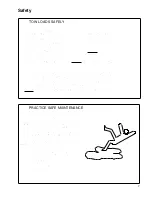
Страница 9: ...Safety TOW LOADS SAFELY PRACTICE SAFE MAINTENANCE 7 ...

Страница 10: ...Safety AVOID HIGH PRESSURE FLUIDS CHARGE ROW MARKER HYDRAULIC SYSTEM 8 ...

Страница 11: ...roper chain alignment on drive sprockets G Correct sprocket selection and slot width for seed type and size G Drill adjusted for level field operation G Lower drill while moving forward to avoid plugging G Check seed depth and adjust accordingly G Allow no riders The CrustBuster 3200 Trash Shank Drill is built for the aggressive farmer who needs big drill economy small drill portability and in fie...

Страница 12: ...kershaft lug and ports to left side of drill Figure 3 STEP 4 Install one hose carrier to tab on back center stub of A frame with 1 2 x 1 1 2 HHCS lock washer and hex nut STEP 5 Position wing carrier assembly approxi mately two inches 2 behind fold lug on A frame Insert 3 4 x 6 HHCS with lock washer and hex nut in bottom clamp of wing carrier DO NOT tighten now wing carrier may need to be adjusted ...

Страница 13: ... small stop on wing frame keeps pin from turning Se cure with 1 1 2 hex nut Tighten set screw in nut Lower wing to ground At tach plastic tube on inside cup of drill box to shank feed tube located on hinge Secure with hose clamp Use the same procedure to assemble opposite wing Figure 8 STEP 9 Refer to Figure 9 Front pull bars are installed between plates of fold lug located on front of A frame The...

Страница 14: ...side of drill to wing wheel rockershaft Install 5 bolt rim and tire assembly to hub Follow the same proce dure on opposite wing rockershaft STEP 15 Mount selector valve plate to selector valve bracket with two 2 3 8 x 1 HHCS nuts and lock washers Attach valve to plate with two 2 5 16 x 1 HHCS and lock washers Valve is mounted with handle up and two port side forward Intall fittings and hoses per F...

Страница 15: ... Adpt Tee 3 4 JICM 7 4 600098 Adpt 90E 3 8 NPTM x 3 8 NPTF Sw 8 4 465385 Quick Coupler 3 4 FOR 9 1 462887 Hose 3 8 x 24 3 8 NPTM 10 1 462911 Hose 3 8 x 44 3 8 NPTM 11 1 463000 Hose 3 8 x 84 3 8 NPTM 12 1 466920 Hose 3 8 x 98 3 8 NPTM 13 2 466383 Hose x 155 NPTM x 3 4 MOR 14 2 470211 Hose 3 8 x 175 3 8 NPTM x 3 4 JICF Sw 15 2 470229 Hose 3 8 x 185 3 8 NPTM x 3 4 JICF Sw 16 2 468819 Hose x 255 3 4 M...

Страница 16: ...shaft up and install four 4 6 bolt rim and tire assem blies to hubs STEP 3 Refer to Figure 3 Rotate rockershaft down and install 4 x 8 hydraulic cylinder base end to A frame lug ram end to rockershaft lug and ports to left side of drill STEP 4 Install one hose carrier to tab on back center stub of A frame with 1 2 x 1 1 2 HHCS lock washer and hex nut STEP 5 Position wing carrier assemblyon A frame...

Страница 17: ...x nut Tighten set screw in nut Lower wing to ground At tach plastic tube on inside cup of drill box to shank feed tube located on hinge Secure with hose clamp Use the same procedure to assemble opposite wing Figure 8 STEP 9 Refer to Figure 9 Install front pull bar swivels into holes in front of A frame Secure with 1 x 4 1 2 HHCS 1 4 thick flat washers 1 4 x 2 1 2 OD x 1 1 32 ID and lock nuts The f...

Страница 18: ...ld hoses up over hinge area STEP 14 WING LEVEL ADJUSTMENTS Activate hydraulics to wing and center frame cylin ders to raise drill Level top of 4 x 6 center frame tube using hitch jack Refer to Figure 14 Check each wing about midway out on 4 x 6 tube to make sure it is level If wings require leveling remove two 2 3 8 bolts which hold large hex plate on top of hinge Loosen set screw in side of 1 1 2...

Страница 19: ...w 6 2 465278 Adpt Tee 3 4 JICM 7 4 465310 Adpt 90E 3 4 MOR x 3 4 JICM 8 4 465385 Quick Coupler 3 4 FOR 9 1 462887 Hose 3 8 x 24 3 8 NPTM 10 1 462911 Hose 3 8 x 44 3 8 NPTM 11 1 463588 Hose 3 8 x 144 3 8 NPTM 12 1 468314 Hose 3 8 x 156 3 8 NPTM 13 2 466383 Hose x 155 NPTM x 3 4 MOR 14 2 470245 Hose 3 8 x 224 3 4 JICF Sw 15 2 470252 Hose 3 8 x 236 3 4 JICF Sw 16 2 470237 Hose x 312 3 4 MOR x 3 4 JIC...

Страница 20: ...ment for several hours check all bolts to be sure they are tight 4 At the end of each season clean the feed slot with diesel fuel This will provide a protective coating against rust and corrosion Be careful when cleaning with diesel fuel so that it does not ignite Use only in a well ventilated area and away from sparks or flames 5 Clean and repack all wheel bearings at the beginning of each season...

Страница 21: ...e center box when unit is folded A large part of this is the wing press wheels which are hidden from your line of view from tractor 5 When transporting be particularly careful when crossing sharp dips or ridges in road or if you have to hang press wheels over shoulder of the road Press wheels could drag and cause dam age to the implement 6 Reduce speed when transporting over uneven or rough terrai...

Страница 22: ... outward toward wing To tip wing FORWARD turn indicator holes to front of drill To tip wing BACKWARDS turn indicator holes to back of drill Level both wings and re secure 3 8 bolts 1 1 2 nut and set screws Refer to Figure below CAUTION Before filling grain boxes properly hitch the drill to tractor to pre vent possibility of drill tipping over back ward 3 Before filling box with seed rotate seed sh...

Страница 23: ...e hex shaft slightly to position the particular seed cup correctly Close the slot width firmly against the measuring device At the cup next to the wobble slot adjusting handle position the gauge to equal the slot width you have just measured with the keystock by loosening with a screwdriver and sliding in or out Small changes in rate can be made by opening or closing slot width To close the slot w...

Страница 24: ...e determined rate 6 Adjust seeding rate accordingly to compensate for any variation between the rate desired and the amount actually drilled If a more accurate check is required raise the drill out of the ground and check in the following manner 1 Place seed in the drill box and a container under each feed cup 2 Set the seeding rate on drill for desired quantity per acre as shown on the rate chart...

Страница 25: ...g CAUTION More down pressure will raise drill out of ground as box empties With adjustment clamp all the way up set your planting depth Move clamp down to within 1 4 of presswheel spring after depth is set Sprocket Locations 23 ...

Страница 26: ... tooth sprocket is a special order sprocket Rates are based on 60 pound test weight alfalfa BARLEY Seeding Rate SEEDING RATES POUNDS PER ACRE SPROCKETS 10 Spacing 12 Spacing A B C D Slot e e e e Slot Slot Slot e e e e Slot Slot 6 16 5 20 14 16 21 12 14 16 6 14 5 20 15 20 24 14 16 20 6 11 5 20 20 24 30 16 21 25 6 11 5 16 25 31 37 21 25 31 6 16 11 20 30 37 45 25 31 37 6 14 11 20 35 44 51 29 36 44 6 ...

Страница 27: ... 35 47 70 29 39 58 6 11 16 14 41 54 81 34 45 68 CORN Seeding Rate SEEDING RATES POUNDS PER ACRE SPROCKETS 10 Spacing 12 Spacing A B C D Slot e e e e Slot Slot Slot e e e e Slot Slot 6 16 5 20 7 10 12 6 9 10 6 14 5 20 9 12 14 7 10 12 6 11 5 20 11 15 19 9 12 15 6 11 5 16 14 19 22 11 16 19 6 16 11 20 16 22 27 14 19 22 6 14 11 20 19 26 31 15 21 26 6 16 14 20 20 29 35 17 24 29 6 14 11 16 22 32 40 19 27...

Страница 28: ... 179 222 124 149 185 6 11 16 5 189 227 282 157 189 235 NOTE Rates are based on 48 pound test weight cotton seed FESCUE Seeding Rate SEEDING RATES POUNDS PER ACRE SPROCKETS 10 Spacing 12 Spacing A B C D d d d d Slot Slot e e e e Slot d d d d Slot Slot e e e e Slot 6 34 5 20 2 4 5 2 2 4 6 34 5 16 4 5 6 2 4 5 6 34 5 14 4 6 7 3 4 6 6 34 5 11 5 6 9 4 5 7 6 16 5 20 6 7 10 5 6 9 6 14 5 20 6 9 11 6 7 9 6 ...

Страница 29: ...ates are based on 50 pound test weight millet MILO Seeding Rate SEEDING RATES POUNDS PER ACRE SPROCKETS 10 Spacing 12 Spacing A B C D Slot d d d d Slot Slot Slot d d d d Slot Slot 6 34 5 20 4 6 9 2 5 7 6 34 5 16 5 9 10 4 6 9 6 34 5 14 6 9 12 4 7 10 6 34 5 11 6 11 15 5 10 12 6 16 5 20 7 14 17 6 11 15 6 14 5 20 9 16 20 7 14 17 6 11 5 20 11 20 26 9 16 21 6 11 5 16 14 25 32 11 21 27 6 16 11 20 16 30 4...

Страница 30: ...5 186 106 137 155 6 11 16 5 162 210 237 135 175 197 NOTE Rates are based on 32 pound test weight oats PINTO BEANS Seeding Rate SEEDING RATES POUNDS PER ACRE SPROCKETS 10 Spacing 12 Spacing A B C D Slot e e e e Slot Slot Slot e e e e Slot Slot 6 16 5 20 9 11 14 7 10 11 6 14 5 20 10 14 16 9 11 14 6 11 5 20 12 17 21 11 14 17 6 11 5 16 16 21 26 14 17 21 6 16 11 20 20 26 31 16 21 26 6 14 11 20 22 30 36...

Страница 31: ...4 261 149 186 217 6 11 16 5 227 284 331 190 236 276 NOTE Rates are based on 45 pound test weight rice RYE Seeding Rate SEEDING RATES POUNDS PER ACRE SPROCKETS 10 Spacing 12 Spacing A B C D Slot e e e e Slot Slot Slot e e e e Slot Slot 6 16 5 20 17 22 29 14 19 24 6 14 5 20 20 25 32 16 21 27 6 11 5 20 25 32 41 21 27 35 6 11 5 16 31 41 52 26 34 44 6 16 11 20 37 49 62 31 41 52 6 14 11 20 44 56 72 36 4...

Страница 32: ... rates in excess of 70 pounds per acre and traveling at speeds over 4 miles per hour one must use the slot to attain the proper seeding rate as shown If seeding below 70 pounds per acre the slot is recommended for seed placement accuracy SUNFLOWER Seeding Rate SEEDING RATES POUNDS PER ACRE SPROCKETS 10 Spacing 12 Spacing A B C D Slot e e e e Slot Slot Slot e e e e Slot Slot 6 34 5 20 2 4 5 2 4 4 6...

Страница 33: ...are based on 60 pound test weight wheat Plant Populations Per Acre at Various Row Spacings Plants Per Foot Spacing Between Rows Of Row 7 5 in 8 in 10 in 14 in 18 in 20 in 40 in 20 1 792 180 1 306 800 1 045 440 746 740 580 800 522 700 261 360 18 1 612 962 1 176 120 940 896 672 066 522 720 470 530 235 244 15 1 344 128 980 100 784 080 560 055 435 600 392 025 196 020 12 1 075 308 784 080 627 264 448 0...

Страница 34: ...32 A Frame 32 ...

Страница 35: ...ouble Selector Valve Mount Bracket 15 935916 Hydraulic Cylinder Hold Down 16 959098 Fold Slide Weldment 17 959106 Slide Bar Weldment Item Part No Description 18 953026 Pull Bar Pin 19 959072 Fold Arm Pin 20 959692 Pull Bar Slide 21 151118 Bushing 22 334870 HHCS 1 x 4 23 333732 HHCS 1 x 6 1 2 24 335174 HHCS 3 4 x 2 1 2 25 334789 HHCS 1 x 3 1 2 26 330100 HHCS 1 2 x 4 1 2 27 330126 HHCS 1 2 x 5 1 2 2...

Страница 36: ...40 A Frame 34 ...

Страница 37: ...c Cylinder 3 x 40 13 332106 HHCS 1 x 4 1 2 14 330373 HHCS 1 x 9 15 331744 HHCS 1 x 10 1 2 16 330126 HHCS 1 2 x 5 1 2 Item Part No Description 17 01147800 HHCS 1 2 x 1 1 2 18 330100 HHCS 1 2 x 4 1 2 19 334870 HHCS 1 x 4 20 330597 Hex Nylock 1 21 332809 HHCS 1 x 5 22 01172600 HHCS 1 x 2 1 2 23 333575 Hex Nut 1 1 2 w 5 16 Set Screw 24 330142 Lock Washer 1 2 25 330134 Hex Nut 1 2 26 330159 Flat Washer...

Страница 38: ...Center Frame Section 36 ...

Страница 39: ...g 13 956854 Walkboard 14 337634 U bolt 1 2 x 6 x 7 15 337642 Carriage Bolt 1 2 x 5 16 334458 HHCS 1 2 x 6 Item Part No Description 17 330282 HHCS 3 4 x 7 18 335125 HHCS 3 4 x 2 19 333575 Hex Nut 1 1 2 w 5 16 Set Screw 20 330142 Lock Washer 1 2 21 330134 Hex Nut 1 2 22 330332 Lock Washer 3 4 23 330290 Hex Nut 3 4 24 330183 Flat Washer 5 8 25 331223 Square Head Set Screw 5 8 x 1 3 4 26 331538 Hex Ja...

Страница 40: ...32 Left Wing Section 38 ...

Страница 41: ... 13 958801 Left Wing Frame 14 958918 Hinge Pin 15 333575 Hex Jam Nut 1 w 5 16 Set Screw Item Part No Description 16 843193 Front Row Tooth Assembly w Point Hard Surfaced Shoe 17 959304 Front Row Tooth Clamp 4 x 6 18 334458 HHCS x 6 19 335125 HHCS 3 4 x 2 20 337634 U bolt x 6 x 7 21 337642 Carriage Bolt x 5 22 330183 Flat Washer 5 8 23 460451 Clevis Pin 24 460469 Clip Pin 25 330142 Lock Washer 26 3...

Страница 42: ...32 Right Wing Section 40 ...

Страница 43: ... w Hard Surfaced Shoe Bumper 13 958793 Right Wing Frame 14 958918 Hinge Pin Item Part No Description 15 333575 Hex Jam Nut 1 1 2 w 5 16 Set Screw 16 843193 Front Row Tooth Assembly w Point Hard Surfaced Shoe 17 959304 Front Row Tooth Clamp 4 x 6 18 334458 HHCS 1 2 x 6 19 335125 HHCS 3 4 x 2 20 337634 U bolt 1 2 x 6 x 7 21 337642 Carriage Bolt 1 2 x 5 22 330183 Flat Washer 5 8 23 460451 Clevis Pin ...

Страница 44: ...40 Left Wing Section 42 ...

Страница 45: ... Frame 14 958918 Hinge Pin 15 333575 Hex Jam Nut 1 1 2 w 5 16 Set Screw Item Part No Description 16 843193 Front Row Tooth Assembly w Point Hard Surfaced Shoe 17 959304 Front Row Tooth Clamp 4 x 6 18 334458 HHCS 1 2 x 6 19 335125 HHCS 3 4 x 2 20 337634 U bolt 1 2 x 6 x 7 21 337642 Carriage Bolt 1 2 x 5 22 330183 Flat Washer 5 8 23 460451 Clevis Pin 24 460469 Clip Pin 25 330142 Lock Washer 1 2 26 3...

Страница 46: ...40 Right Wing Section 44 ...

Страница 47: ... w Hard Surfaced Shoe Bumper 13 958819 Right Wing Frame 14 958918 Hinge Pin Item Part No Description 15 333575 Hex Jam Nut 1 1 2 w 5 16 Set Screw 16 843193 Front Row Tooth Assembly w Point Hard Surfaced Shoe 17 959304 Front Row Tooth Clamp 4 x 6 18 334458 HHCS 1 2 x 6 19 335125 HHCS 3 4 x 2 20 337634 U bolt 1 2 x 6 x 7 21 337642 Carriage Bolt 1 2 x 5 22 330183 Flat Washer 5 8 23 460451 Clevis Pin ...

Страница 48: ...Center Drive Assembly 46 ...

Страница 49: ...ock Collar 22 936047 Bearing Mount Hanger 23 194639 Bolt Plate 24 302802 Hex Shaft 5 8 x 31 1 8 Item Part No Description 25 432930 Chain 32 x 37 Links 26 918714 Chain Guard Flange 27 250860 Right Chain Guard Plate 28 250829 Left Chain Guard Plate 29 430199 Sprocket 16T w 5 8 Hex Bore 30 01150200 HHCS 1 4 x 1 2 31 331835 HHCS 1 4 x 1 32 01057900 HHCS 1 4 x 3 4 33 333690 Carriage Bolt 1 2 x 4 34 330...

Страница 50: ...Left Drive Assembly 48 ...

Страница 51: ...ate 21 140665 Lock Collar 22 936047 Bearing Mount Hanger 23 194639 Bolt Plate 24 302802 Hex Shaft 5 8 x 31 1 8 Item Part No Description 25 432930 Chain 32 x 37 Links 26 918714 Chain Guard Flange 27 250860 Right Chain Guard Plate 28 250829 Left Chain Guard Plate 29 430199 Sprocket 16T w 5 8 Hex Bore 30 01150200 HHCS 1 4 x 1 2 31 331835 HHCS 1 4 x 1 32 01057900 HHCS 1 4 x 3 4 33 333690 Carriage Bolt...

Страница 52: ...Right Drive Assembly 50 ...

Страница 53: ...Plate 21 140665 Lock Collar 22 936047 Bearing Mount Hanger 23 194639 Bolt Plate Item Part No Description 24 302802 Hex Shaft 5 8 x 31 1 8 25 432930 Chain 32 x 37 Links 26 918714 Chain Guard Flange 27 250860 Right Chain Guard Plate 28 250829 Left Chain Guard Plate 29 430199 Sprocket 16T w 5 8 Hex Bore 30 01150200 HHCS 1 4 x 1 2 31 335133 HHCS 1 4 x 1 3 4 32 01057900 HHCS 1 4 x 3 4 33 333690 Carriag...

Страница 54: ...Box Assembly 52 ...

Страница 55: ...611 Nylock 5 16 Item Part No Description 18 221317 Latch Handle 19 01011600 HHCS 5 16 x 1 1 4 20 335703 HHCS 3 8 x 1 21 149385 Box Lid Bushing 22 330837 Hex Nylock Nut 3 8 23 601989 Pop Rivet 3 16 x 1 4 24 570341 Drill Lid Latch w Hook 25 333542 HHCS 5 16 x 5 8 26 330845 Lock Washer 5 16 27 331835 HHCS 1 4 x 1 28 02016400 Flat Washer 1 4 29 00671800 Trim Lock 30 Box Bottom Weldment 958587 126 x 10...

Страница 56: ...76 Clevis Hitch 2 306118 Hitch Pin 3 02450500 HHCS 5 16 x 3 4 331611 Hex Nylock Nut 5 935700 Hitch Weldment 6 935924 Hose Carrier 7 331926 HHCS 1 2 x 2 8 330142 Lock Washer 1 2 9 330134 Hex Nut 1 2 10 605899 Ratchet Turnbuckle Assembly 54 ...

Отзывы: