


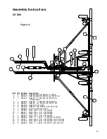


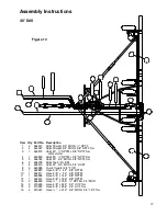


Assembly Instructions
32' Drill
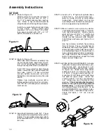
STEP 17 FOLD ADJUSTMENTS. Install cylinder
lockout in center frame cylinder and se-
cure with 5/16" x 2 3/4" pin. Switch selec-
tor valve to fold cylinder. Slowly fold drill
checking for clearances and binding.
Move wing carrier so stands contact wing
frames at a clear location. Tighten
3/4" x 6" HHCS to hold wing carrier. If
wings do not fold fully, adjust clevis screw
in end of fold arms. Screw in to fold fur-
ther, and out so wing does not fold in as
far.
Raise latches on wing carrier and secure
with 3/4" pins. Raise wing wheels and drill
is ready for transport.
40' Drill
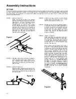
STEP 1
(Refer to Figure 1)
Place main center section in an upright
position standing on hoe points and suit-
able stands. Lift rear of A-frame to align
bolt holes in A-frame with holes in L-
shaped plates on front of main center
frame. Secure with four (4) 1" x 5" HHCS
and lock nuts. Install 1" x 2 1/2" HHCS up
through A-frame plate and center frame
plate on each side of A-frame and secure
with lock nut. Pin jack to jack spool to
hold front of A-frame up.
Figure 1
STEP 2
Spindles and hubs are factory installed in
center rockershaft to lessen field assem-
bly. Rotate center rockershaft up and
install four (4) 6 bolt rim and tire assem-
blies to hubs.
STEP 3
(Refer to Figure 3)
Rotate rockershaft down and install 4" x 8"
hydraulic cylinder base end to A-frame lug
(ram end to rockershaft lug) and ports to
left side of drill.
STEP 4
Install one hose carrier to tab on back
center stub of A-frame with 1/2" x 1 1/2"
HHCS, lock washer, and hex nut.
STEP 5
Position wing carrier assembly on A-frame
mounting plates. Secure with 5/8" x 2"
HHCS, lock washers, and hex nuts.
STEP 6
(Refer to Figure 6)
Place fold slide onto center of A-frame
with cylinder hole toward front. Bolt bot-
tom slide assembly on with eight (8) 1/2"
x 1 1/2" HHCS, flat washer, lock washers,
and hex nuts.
With cylinder pins provided, attach base
end of 3" x 40" hydraulic cylinder to fold
cylinder lug. (Ports of cylinder to right side
of drill.) Lift ram end of cylinder and slip
fold cylinder hold-down over A-frame
approximately twenty inches (20") from
base of cylinder. Lower cylinder into hold-
down, move fold slide to align with ram
end of fold cylinder, and attach with cylin-
der pin. Bolt cylinder hold-down to A-
frame with 1/2" x 5 1/2" HHCS, lock
washer, and hex nut.
If a selector valve
is used
, its mounting bracket is installed
on top of cylinder hold-down with a
1/2" x 5 1/2" HHCS.
If no selector valve
is used,
install a 1/2" x 4 1/2" HHCS, lock
washer, and hex nut in top of cylinder
hold-down.
Figure 6
Figure 3
14
Содержание 3200
Страница 1: ...3200 Trash Shank OWNER S MANUAL 01 10 601401 ...
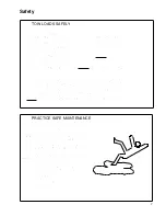
Страница 5: ...Safety RECOGNIZE SAFETY INFORMATION UNDERSTAND SIGNAL WORDS FOLLOW SAFETY INSTRUCTIONS 3 ...
Страница 6: ...Safety OPERATE SAFELY AVOID TIP OVERS KEEP RIDERS OFF MACHINE 4 ...
Страница 7: ...Safety HANDLE FUEL SAFELY AVOID FIRES PREPARE FOR EMERGENCIES WEAR PROTECTIVE CLOTHING 5 ...
Страница 8: ...Safety USE SAFETY LIGHTS AND DEVICES TRANSPORT SAFELY 6 ...
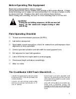
Страница 9: ...Safety TOW LOADS SAFELY PRACTICE SAFE MAINTENANCE 7 ...
Страница 10: ...Safety AVOID HIGH PRESSURE FLUIDS CHARGE ROW MARKER HYDRAULIC SYSTEM 8 ...
Страница 34: ...32 A Frame 32 ...
Страница 36: ...40 A Frame 34 ...
Страница 38: ...Center Frame Section 36 ...
Страница 40: ...32 Left Wing Section 38 ...
Страница 42: ...32 Right Wing Section 40 ...
Страница 44: ...40 Left Wing Section 42 ...
Страница 46: ...40 Right Wing Section 44 ...
Страница 48: ...Center Drive Assembly 46 ...
Страница 50: ...Left Drive Assembly 48 ...
Страница 52: ...Right Drive Assembly 50 ...
Страница 54: ...Box Assembly 52 ...