


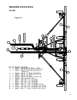


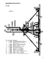


Assembly Instructions
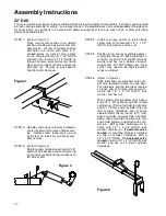
32' Drill
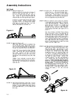
STEP 11
(Refer to Figure 11)
Attach pull bar truss stand to A-frame in
front of fold lug with two (2) 3/4" x
4" x 7 1/2" U-bolts, lock washers, and hex
nuts. Holes in top of stand should be
straight above the front pull bar pivot pins.
Install truss swivel to the top of each hole
in truss stand. These swivels pivot
around a 1 1/4" O.D. x 13/16" I.D. x 9/16"
long spool secured with 3/4" x 2 1/2"
HHCS, flat washer, and lock nut.
Figure 11
STEP 12
(Refer to Figure 12)
Slide tube end of fold arm assembly into
clevis of front pull bar, align holes, insert 1
1/4" x 9 1/2" pin through truss tube down
through front pull bar clevis and fold arm.
Insert 7/8" truss adjusting bolt through
swivel. Install 7/8" hex nut and thread into
truss tube. Install 1 1/4" hex nut on fold
arm pin, tighten and secure set screw.
Follow the same procedure on other side
of drill.
Tighten truss rod bolts so when drill is
folded, pull bars will not catch on A-frame.
Jam 7/8" hex nut to keep truss rod adjust-
ment secure.
Figure 12
STEP 13 Adjust both fold arms to 48 3/4". These
may need minor adjustment when drill is
folded. The adjustable screw ends attach
to the fold slide with 1" x 3 1/2" HHCS and
lock nuts.
STEP 14 Install a 2" x 8" hydraulic cylinder (base
end to frame -- ram end to wheel lug --
ports to inside of drill) to wing wheel
rockershaft. Install 5-bolt rim and tire
assembly to hub. Follow the same proce-
dure on opposite wing rockershaft.
STEP 15 Mount selector valve plate to selector
valve bracket with two (2) 3/8" x 1" HHCS,
nuts, and lock washers. Attach valve to
plate with two (2) 5/16" x 1" HHCS and
lock washers. Valve is mounted with
handle up and two port side forward.
Intall fittings and hoses
per Figure 15 on
page 4
.
Use hose clamps to attach hoses along
front of frames. These are attached to
walkboard and tooth clamp bolts. Cable
wrap and hose carriers hold hoses which
are routed down top of A-frame. Slack in
hoses going to wing cylinders is needed at
the hinge. Attach a hose clamp on front
bolt of inside wing box standoff to hold
hoses up over hinge area.
STEP 16 WING LEVEL ADJUSTMENTS. Activate
hydraulics to wing and center frame cylin-
ders to raise drill. Level top of 4" x 6"
center frame tube using hitch jack.
(Refer
to Figure 16.)
Check each wing about
midway out on 4" x 6" tube to make sure
it is level. If wings require leveling, re-
move two (2) 3/8" bolts which hold large
hex plate on top of hinge. Loosen set
screw in side of 1 1/2" hex nut and loosen
nut. Hinges are set at factory at zero
degrees.
This is indicated by two small
holes in hex plate pointing outward
toward wing.
To tip wing FORWARD,
turn indicator holes to front of drill. To tip
wing BACKWARDS, turn indicator holes
to back of drill. Level both wings and re-
secure 3/8" bolts, 1 1/2" nut, and set
screws.
Figure 16
12
Содержание 3200
Страница 1: ...3200 Trash Shank OWNER S MANUAL 01 10 601401 ...
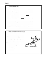
Страница 5: ...Safety RECOGNIZE SAFETY INFORMATION UNDERSTAND SIGNAL WORDS FOLLOW SAFETY INSTRUCTIONS 3 ...
Страница 6: ...Safety OPERATE SAFELY AVOID TIP OVERS KEEP RIDERS OFF MACHINE 4 ...
Страница 7: ...Safety HANDLE FUEL SAFELY AVOID FIRES PREPARE FOR EMERGENCIES WEAR PROTECTIVE CLOTHING 5 ...
Страница 8: ...Safety USE SAFETY LIGHTS AND DEVICES TRANSPORT SAFELY 6 ...
Страница 9: ...Safety TOW LOADS SAFELY PRACTICE SAFE MAINTENANCE 7 ...
Страница 10: ...Safety AVOID HIGH PRESSURE FLUIDS CHARGE ROW MARKER HYDRAULIC SYSTEM 8 ...
Страница 34: ...32 A Frame 32 ...
Страница 36: ...40 A Frame 34 ...
Страница 38: ...Center Frame Section 36 ...
Страница 40: ...32 Left Wing Section 38 ...
Страница 42: ...32 Right Wing Section 40 ...
Страница 44: ...40 Left Wing Section 42 ...
Страница 46: ...40 Right Wing Section 44 ...
Страница 48: ...Center Drive Assembly 46 ...
Страница 50: ...Left Drive Assembly 48 ...
Страница 52: ...Right Drive Assembly 50 ...
Страница 54: ...Box Assembly 52 ...