


Crestron
UPX-2
Universal Presentation Processor
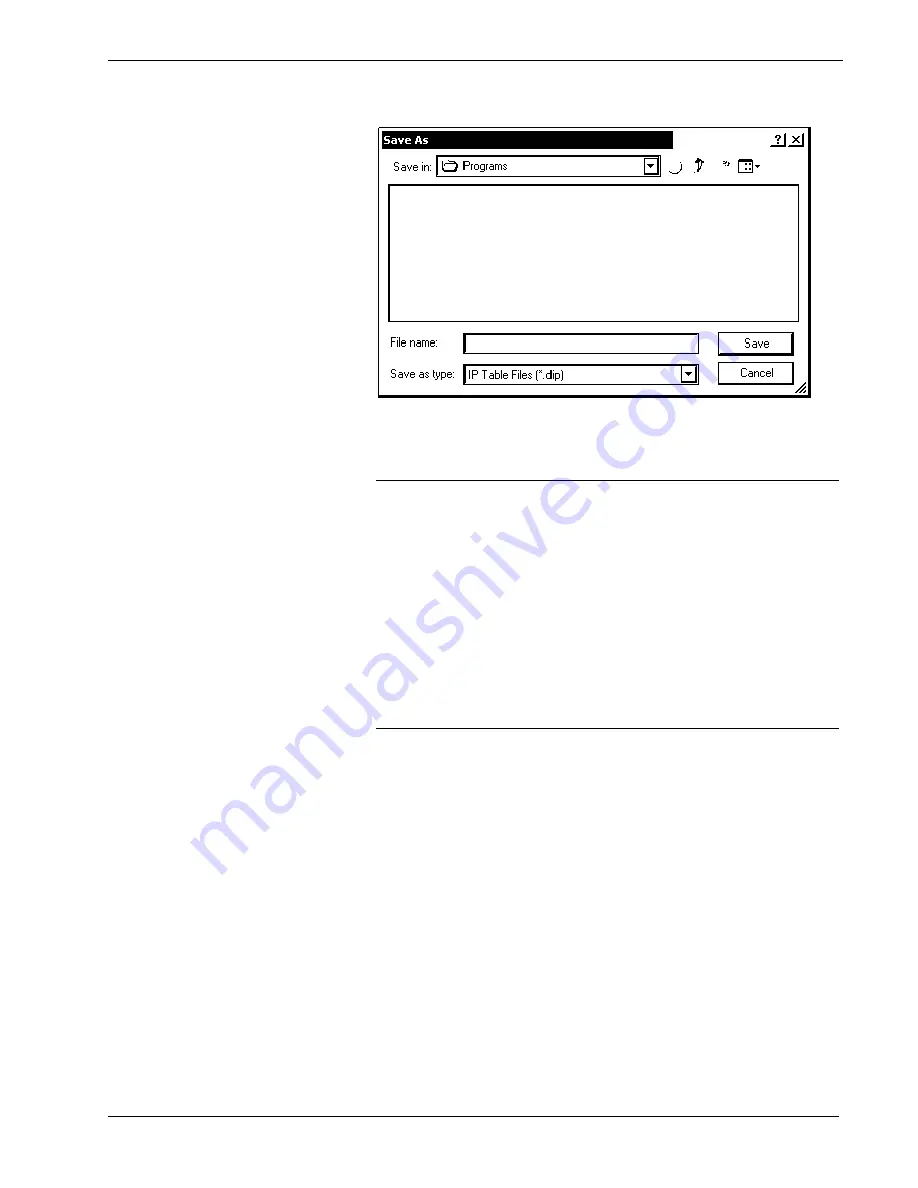
“Save As” Window
8. Once all of the control systems have been listed, click
Send to Device
on
the “IP Table” window
to upload the IP table to the UPX-2. The UPX-2 will
reboot and all of the table entries will be listed in black.
CAUTION:
At power up or reboot, the touchpanel will cycle through
colors and the Crestron logo screen for approximately 2.5 minutes prior to
displaying the progress bar. This is a normal part of the boot up process.
Do
not
turn off power to the UPX-2 while it is rebooting. Damage may occur.
NOTE:
If a control system is to communicate with the UPX-2 over
TCP/IP, the control system's IP table must have an entry for the UPX-2. The
entry should list the UPX-2’s IP ID and the internal gateway IP address
127.0.0.1. For more information, refer to the latest version of the Crestron
e-Control Reference Guide (Doc. 6052).
NOTE:
When an IP table is sent to the UPX-2, the UPX-2 will reboot and
the previously loaded IP table will be overwritten.
Troubleshooting Communications
Use the following checklist if communication cannot be established with the UPX-2.
1. Verify that you are using the correct cables. As described previously, an
RS-232 connection requires a null modem serial cable. TCP/IP connection
requires a CAT5 cable with 8-pin RJ-45 connectors.
2. With a serial connection, verify that the correct COM port on the PC has
been selected. Some computers have more than one COM port; some may
be internal (e.g., for a modem). Consult the manufacturer’s documentation
for further information about the COM ports on your PC.
3. Remove and reapply power to the UPX-2.
4. If communication still cannot be established, contact Crestron customer
service.
68
¥
Universal Presentation Processor: UPX-2
Operations Guide – DOC. 6276B


