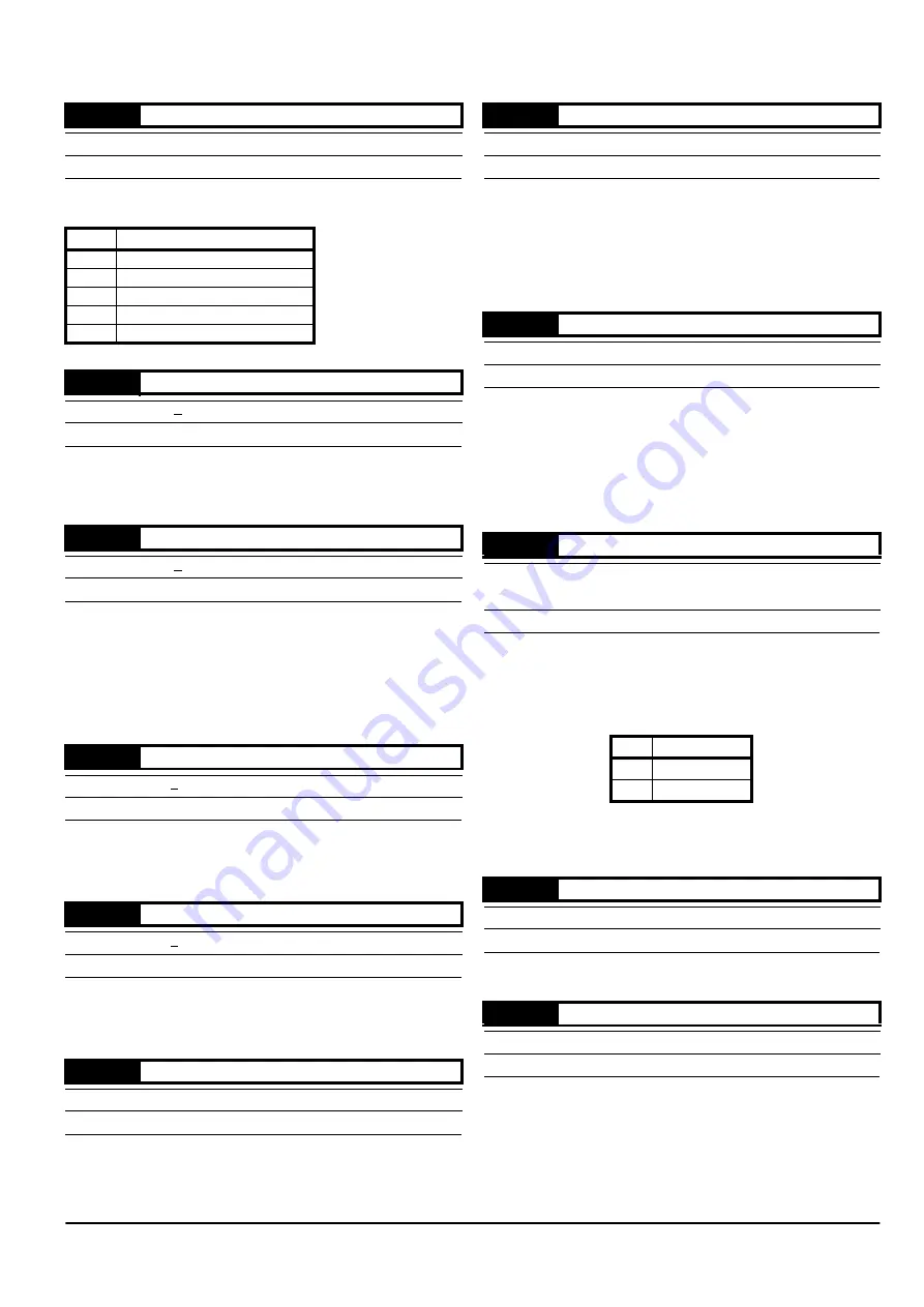
*
M’Ax User Guide
45
Issue Number: 4
0.02
indicates which speed reference has been selected by
0.30
Reference selector, as follows:
0.03
indicates the value of the speed reference that has been selected
by
0.30
Reference selector (see
0.02
Reference selected indicator) and
the value of
0.06
{1.04} Reference offset.
0.04
indicates the instantaneous value of the sum of the following:
0.03
{1.01} Value of selected reference, and
3.22
Hard speed
reference only enabled if
3.23
Hard speed reference selector set to
1
.
During acceleration and deceleration under ramp control (see
0.25
,
0.26
), [0.04] will differ from the sum of the applied speed reference and
reference offset.
0.05
indicates the instantaneous value of the speed feedback. This is
supplied to the Drive by the CT-Coder via the
SLM
.
When the Drive is not in current limit, [0.04] = [0.05].
Set
0.06
at the required value of offset (eg. amount of trim) to be added
to or subtracted from the selected speed reference (see
0.02
Reference
selected indicator).
I
OL
Maximum overload current from the Drive (2 x FLC)
0.07
indicates the average RMS phase current to the motor.
n
MAX
Maximum speed of the motor (defined by the motor via the
SLM
)
0.08
is used for defining the maximum speed at which the Drive will drive
the motor. Excessive speed references are clamped to [0.08].
If the motor speed exceeds [0.08] (e.g. under torque control), the Drive
will trip allowing the motor to coast. (See trip
OU.SPd
in Appendix B
Diagnostics.)
Stiffness angle is defined as the angular displacement of the motor shaft
that would cause the Drive to deliver a torque-producing current
equivalent to the value of FLC (without field weakening).
Enter a suitable value in
0.09
in order to define the dynamic performance
of the system.
See
0.10
Load inertia and Specifying shaft stiffness and load inertia in
Appendix D Optimising the Dynamic Performance.
J
L
Motor load
The measurement units are defined by the motor via the
SLM
.
Use the following procedure for adjusting
0.10
:
1. Unlock security.
2. Ensure
0.11
Inertia units selected is set as follows:
3. Enter into
0.10
the value of load inertia seen by the motor.
See
0.09
Compliance angle and Specifying shaft stiffness and load
inertia in Appendix D Optimising the Dynamic Performance.
See parameter
0.10
Load inertia above
Ensure
0.12
is set at
1
before adjusting any of the following parameters:
0.13
Speed-loop proportional gain Kp1
0.14
Speed-loop integral gain Ki1
0.15
Speed-loop derivative gain Kd1
See Gain sequencing in Appendix D Optimising the Dynamic
Performance.
0.02
Reference selected indicator
{1.49}
ô
1 ~ 5
RO
Uni
P
0.02
Speed reference selected
1
Analog speed reference
2
Analog speed reference
3
Preset speed reference
4
Keypad speed reference
5
Pulse reference
0.03
Value of selected reference
{1.01}
ô
+[0.08]
RO
Bi
P
RPM
0.04
Final speed reference
{3.01}
ô
+[0.08]
RO
Bi
P
RPM
0.05
Speed feedback
{3.02}
ô
+[0.08]
RO
Bi
P
RPM
0.06
Reference offset
{1.04}
ô
+[0.08]
ð
0
RW
Uni
0.07
Motor current magnitude
{4.01}
ô
0 ~ I
OL
RO
Uni
P
A
0.08
Maximum reference clamp
{1.06}
ô
0 ~ 7500
ð
n
MAX
RW
Uni
rpm
0.09
Stiffness angle
{3.19}
ô
0.0 ~ 30.0
ð
6.0
RW
Uni
o
0.10
Load inertia
{3.20}
ô
ô
0.01 ~ 600.00kgcm
2
or
0.00001 ~ 0.06kgm
2
ð
J
L
RW
Uni
0.11
Units
0
kgm
2
1
kgcm
2
0.11
Inertia units selected
{5.34}
ô
0 ~ 1
RO
Bit
0.12
Speed-loop PID gains selector
{3.16}
ô
0 ~ 3
ð
1
RW
Uni
Содержание M'Ax 403
Страница 6: ......
Страница 61: ...M Ax User Guide 55 Issue Number 4 Use this page for notes...
Страница 73: ...M Ax User Guide 67 Issue Number 4 Use this page for notes...
Страница 75: ...M Ax User Guide 69 Issue Number 4...


