*
M’Ax User Guide
29
Issue Number: 4
15. Perform either of the following:
•
Wait eight seconds; the display will return to Status mode
•
Press...
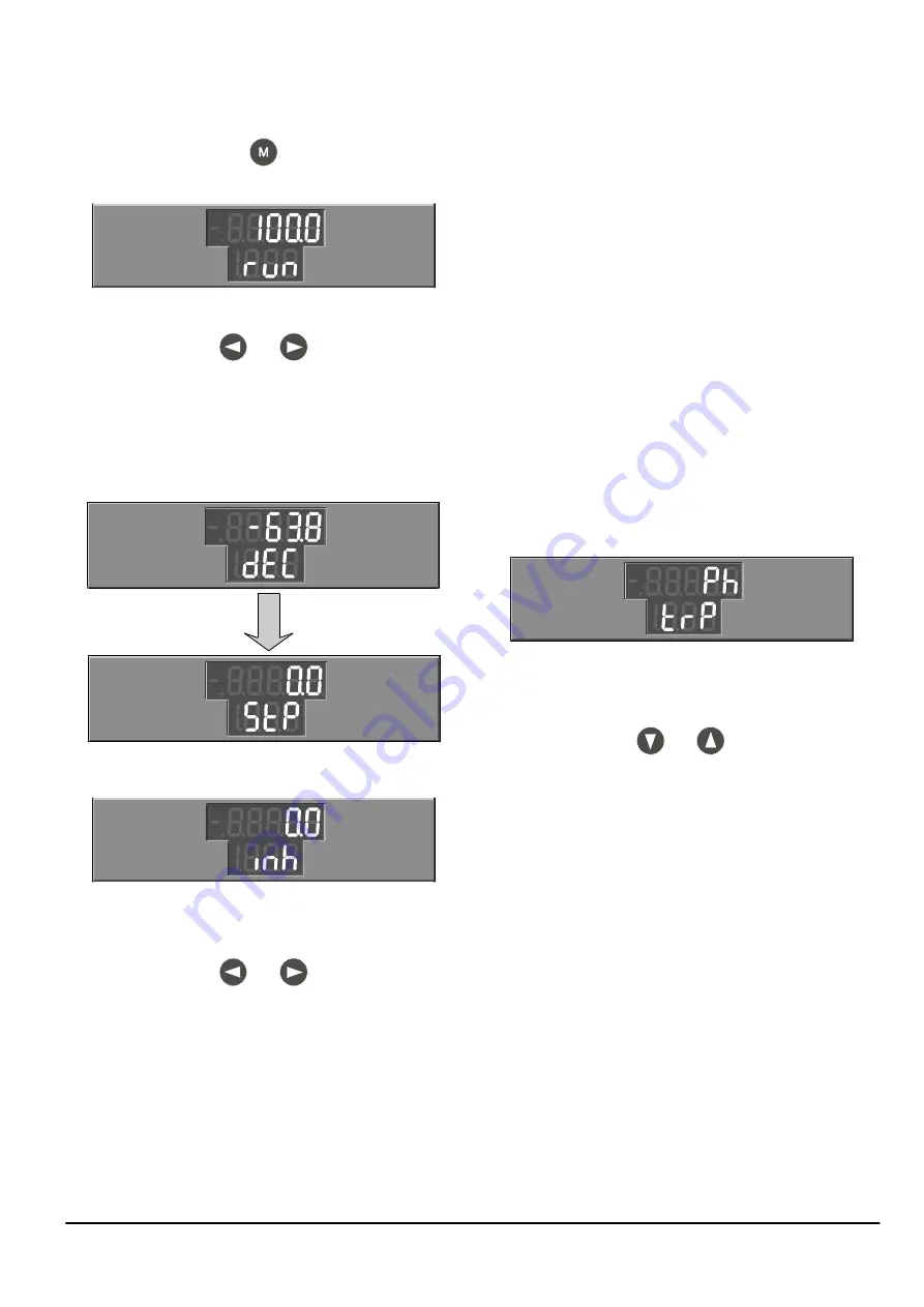
16. The display indicates as follows:
17. Press at the same time...
The value of parameter 0.05 Speed feedback is now displayed on the
upper line of the display.
18. Open the RUN contact. The following occur:
•
The motor decelerates to rest
•
The value indicated on the upper line of the display
correspondingly reduces to zero
•
The lower line of the display shows dEC, then StP
19. Open the Hardware enable contact (or set parameter 6.15 Drive
enable at 0). The display indicates as follows:
20. Initiate the save operation by setting parameter XX.00 at 1000.
Execute the operation by performing either of the following:
•
While the display is in Edit mode, press at the same time:
•
Set parameter 10.38 at 100 (via serial communications)
21. To use the saved values after the next power-up, ensure parameter
0.50 is set at no (0). If you have to change the setting, immediately
afterwards execute the operation, as described in step 20.
Summary
The procedure has shown the following (for version _AN):
•
When the Drive is inhibited (disabled) (i.e. Hardware enable
contact is open or parameter 6.15 Drive enable is set at 0), the lower
line of the display states inh.
•
When the Drive is enabled (i.e. Hardware enable contact is
closed and parameter 6.15 Drive enable is set at 1) but the RUN
contact is open, the lower line of the display states StP.
•
When the RUN contact is closed and the motor is stationary,
accelerating, decelerating or running at a constant speed, the lower
line of the display states run.
•
When the RUN contact has been opened and while the motor is
decelerating, the lower line of the display indicates dEC (when the
deceleration time is sufficiently long).
•
The upper line of the display indicates the value of a parameter;
parameter 0.05 Speed feedback for indicating actual motor speed
and 0.34 Keypad reference for indicating the speed demand were
demonstrated.
•
When the motor is running in the reverse direction, a minus sign
appears in front of the indicated speed value.
Alarms and trips
Alarms and trips are described in Appendix B Diagnostics on page 84.
1.
If an alarm message appears on the lower line of the display, the
Drive continues running, but will trip if the cause of the alarm is not
corrected.
2.
If the Drive trips, the motor will no longer be controlled and will be
allowed to coast. The lower line of the display will indicate as shown
below and the upper line will indicate a trip code:
3.
To clear a trip, correct or remove the cause of the trip, then reset the
Drive by either of the following means...
•
Momentarily close the RESET contact
•
Press:
5.3
Procedure for serial communications
1.
Ensure the signal connections for serial communications have been
made (Figure 2–7).
2.
Perform the procedure in Specifying shaft stiffness and load inertia
on page 94. Failure to perform this procedure will omit essential
steps. It may also result in unstable control of the motor and the
Drive tripping.
3.
Send a read-command to check that parameter 1.14 {0.30}
Reference selector is set at 3. If required, send a write-command to
set it at 3.
4.
Send a read-command to check that parameter 1.15 Preset
reference selector is set at 1. If required, send a write-command to
set it at 1.
5.
Send a read-command to check that parameter 1.21 {0.33} Preset
reference 1 is set at 0.0. If required, send a write-command to set it
at 0.0.
6.
Close the Hardware enable contact .
7.
Send a read-command to check that parameter 8.09 {0.01}
Hardware enable status is set at 1.
8.
Send a read-command to check that parameter 10.03 At zero speed
indicator is set at 1.
and
and
and
Содержание M'Ax 403
Страница 6: ......
Страница 61: ...M Ax User Guide 55 Issue Number 4 Use this page for notes...
Страница 73: ...M Ax User Guide 67 Issue Number 4 Use this page for notes...
Страница 75: ...M Ax User Guide 69 Issue Number 4...


