*
86
M’Ax User Guide
Issue Number: 4
Appendix C
Serial
Communications
Refer to this Appendix for either version to be controlled by serial
communications, in particular, version _
SL
.
C.1
Sequence for editing parameters
Use the following sequence when editing parameters via serial
communications:
1.
Send write-command(s) to edit parameter value(s) with the motor
running or stopped, as appropriate.
2.
Parameters indicated by the letter
R
Parameters on page 44 and Chapter 9 Advanced Parameters on
page 51 require the Drive to be reset before their new values take
effect. If any of these parameters have been adjusted, follow the
procedure in Making new values take effect on page 89.
3.
If required, follow the procedure in Saving new parameter-values on
page 90 to save new parameter-values for future use (the motor can
be running or stopped).
After following this Appendix, refer to Chapter 5 Getting Started on page
28.
C.2
Serial communications protocols and
interfaces
Protocols
Ensure
11.24
Serial comms. protocol selector is set for the protocol to be
used, as follows:
Interfaces
An EIA232 or EIA485 (4-wire only) interface can be used with either
protocol.
Serial communications connections must be made only to one of these
interfaces. The Drive automatically detects which is used.
(See also Signal connections for remote control by serial
communications in Chapter 2 Connecting the Drive.)
C.3
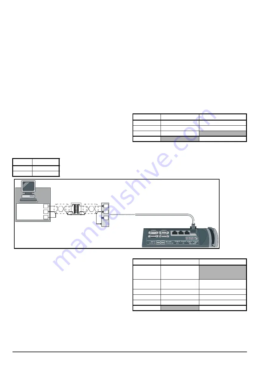
EIA232 interface
An EIA232 serial communications link allows a single Drive to be
controlled and monitored by a host PC, and can be used only for setting-
up purposes.
Serial communications connections
Connector:
MULTIDROP IN/PC
Connect an isolation device between the Drive and PC.
See Figure 2-7 for other signal connections that must be made.
Figure C.1
Connections for an EIA232 link
C.4
EIA485 interface
An EIA485 serial communications link allows up to 81 devices to be
controlled and monitored by a host PLC. The devices can be Drives and/
or other equipment having a suitable serial communications interface.
Alternatively a Drive can be designated as the host for controlling and
monitoring other Drives.
Serial communications connections
Connector:
MC/EIA485
Connect a line-termination resistor between the RX and RX\ lines only at
the last Drive or device on the serial link (ie. the unit furthest from the
host). The value of the resistor must be equal to the characteristic
impedance of the cable.
Do not fit resistors to other units in the system, otherwise excessive
signal loss will occur.
See Figure 2-7 for other signal connections that must be made.
11.24
Protocol
0
ANSI
1
MODBUS RTU
Terminal
Name
Function
7
RXD
Receive input
8
TXD
Transmit output
6
0V COMMON
Shell
Cable shield
8
7
TXD
RXD
0V
Isolation
device
MULTIDROP IN/PC
RXD
TXD
EIA232
interface
6
0V COMMON
Shell
3
2
5
Terminal
Name
Function
4
12
15
0V COMMON
6
TX
Transmit output (non-
inverted)
7
TX\
Transmit output (inverted)
13
RX
Receive input (non-inverted)
14
RX\
Receive input (inverted)
Shell
Cable shield
Содержание M'Ax 403
Страница 6: ......
Страница 61: ...M Ax User Guide 55 Issue Number 4 Use this page for notes...
Страница 73: ...M Ax User Guide 67 Issue Number 4 Use this page for notes...
Страница 75: ...M Ax User Guide 69 Issue Number 4...


