background image

2

6.6.4 

Unit settings in the settings menu

6.6.4.1  Launching the settings menu

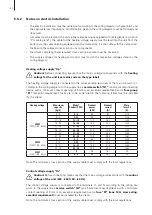
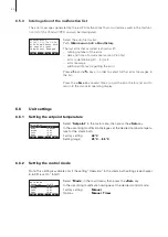
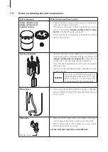
Select the settings menu:
Path: 

Main menu > User > Password entry: 8808 > Settings

Press the 

< >

 and 

< >

 keys in order to select the individual settings in 

the settings menu. 
Detailed information on the different settings are found in the following 
chapters.

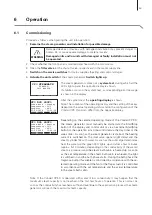
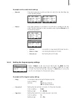
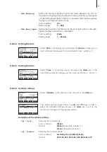
6.6.4.2  Selecting the dialogue language

Select “

Language

” in the settings menu, then press the 

<Set>

 key.

In the upcoming modification dialogue select the desired dialogue lan-
guage. After confirmation, the unit automatically switches to the selected 
dialogue language.
Factory setting: 

country specific

Options: 

divers languages

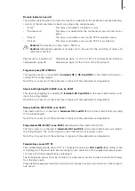
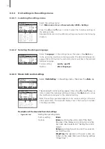
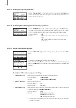
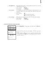
6.6.4.3  Steam bath control settings

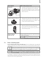
Select “

BathSetting

” in the settings menu, then press the 

<Set>

 key.

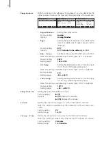
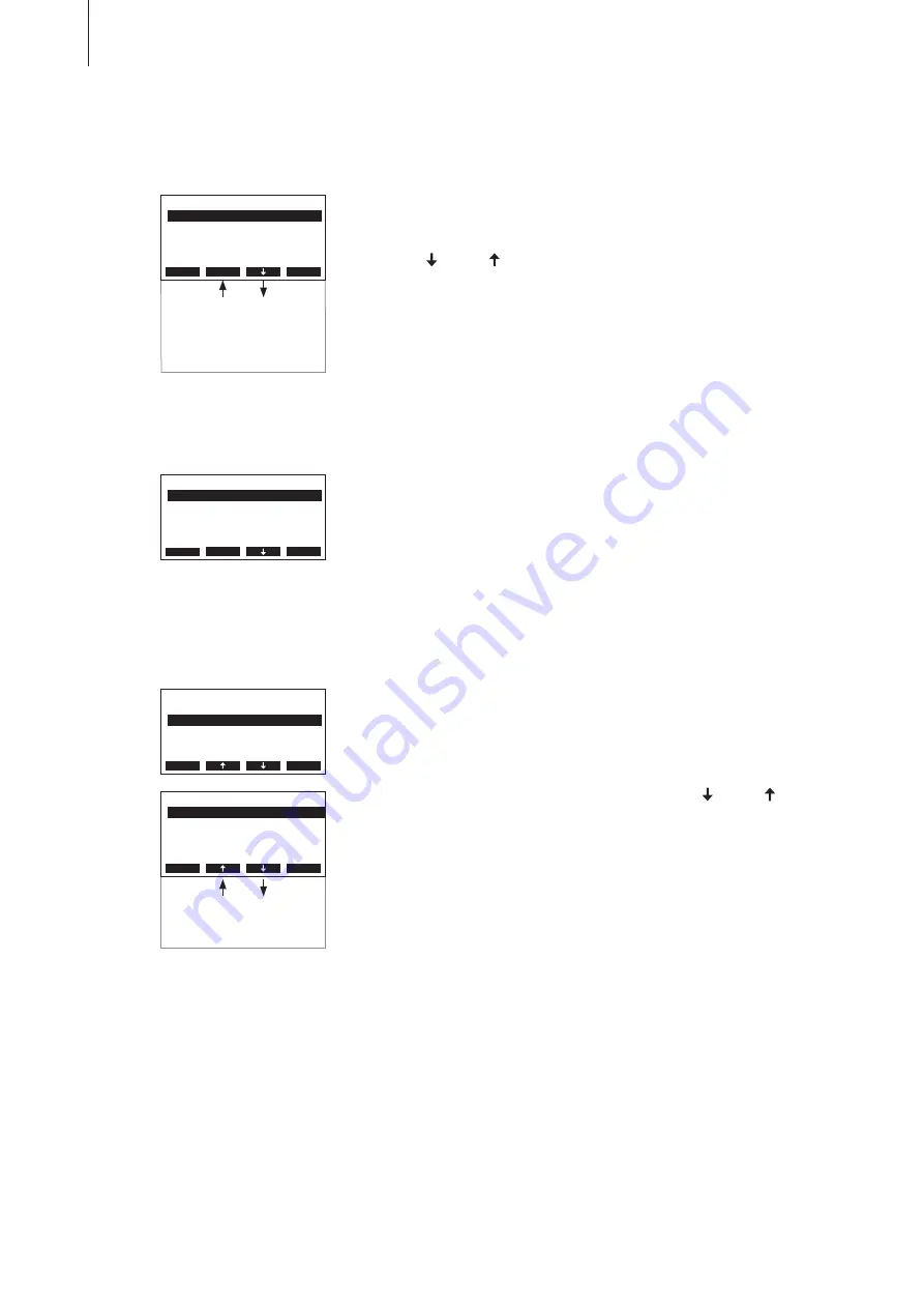
The steam bath control settings appear. 

Press the 

< >

 and 

< >

 keys in 

order to select the individual settings and press the 

<Set>

 key to call up 

the modification dialogue for the selected setting.

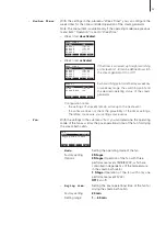
Note: 

The settings available depend on the current settings of the indi-

vidual parameters. The opposite display shows the maximum number 
of settings available.

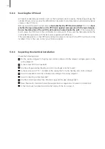
Description of the steam bath control settings

– 

Operation

Setting the operating mode.
Factory setting: 

Intern

Options: 

Intern

 (switching the unit on and off the Start/

Stop key of the display and control unit or via the 
day timer, see chapter ..2 “ Setting the control 
mode”)


Extern

 (switching the unit on and off via an exter-

nal On/Off switch)


WeekTime

 (the operation of the unit is time con-

trolled via the week timer, see following settings 
“WeekTimer”)

Settings

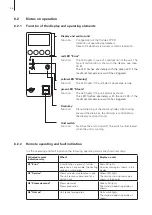
BathSetting :Set

Date        :05.05.08

Time        :12:00

Language    :English

Cylinder    :Set

Esc

Set

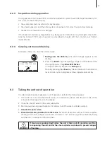
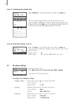
Settings

BathSetting :Set

Date        :05.05.08

Time        :12:00

Language    :English

Cylinder    :Set

Esc

Set

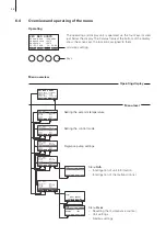
Integr.-Time:2min

Max.Heating :2h

Max.DoorOpen:2min

P-Band      :4°C

BathSetting

Week Timer  :Set

Fan         :Set

Temp.Sensor :Set

Operation   :WeekTime

Temp.Control:Int(PI)

Esc

Set

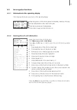
Water Manag.:Set

Remote Test :Set

Bath Test   :Set

GFCI-Mode   :Aus

Contrast    :15

Settings

BathSetting :Set

Date        :05.05.08

Time        :12:00

Language    :English

Cylinder    :Set

Esc

Set

Power Limit :Set

Содержание CP3 D 15 230V3

Страница 1: ...Technical Documentation Steam generator for steam baths 2538965 EN 0806 Condair CP3 D...

Страница 2: ......

Страница 3: ...Taking the unit out of operation 37 6 4 Overview and operating of the menu 38 6 5 Interrogation functions 39 6 5 1 Information in the operating display 39 6 5 2 Interrogation of unit information 39 6...

Страница 4: ...to these publications in the technical documentation 1 Introduction We thank you for having purchased the steam generator Condair CP3 D The steam generator Condair CP3 D incorporates the latest techn...

Страница 5: ...accessed If the equipment changes hands the documentation should be passed on to the new operator If the documentation gets mislaid please contact your Condair supplier Language versions This technic...

Страница 6: ...orised by the owner For safety and warranty reasons any action beyond the scope of this manuals must be carried out only by qualified personnel authorised by the manufacturer It is assumed that all pe...

Страница 7: ...de scribed in chapter 6 3 then wait until the evaporation unit has cooled down sufficiently thus preventing danger of burning Behaviour in case of danger If it is suspected that safe operation is no...

Страница 8: ...eratorsCondairCP3Dareequipped asstandard withanexchangeablesteamcylinder a control with an integrated continuous controller as well as a complete steam bath control connec tion and control of fan ligh...

Страница 9: ...0V 3 50 60Hz 33 8 kW XXXXXXX 11 06 3 2 Identification of the unit The identification of the unit is found on the type plate for the location of the type plate see unit overview Type designation Serial...

Страница 10: ...openings bottom side 10 Drain key 11 Unit switch 12 Steam hose connector option 13 Water cup 14 Filling hose 15 Water supply hose 16 Inlet valve 17 Overflow hose 18 Drain connection not visible 19 Wa...

Страница 11: ...e opens until the required capacity is available again If the required steam capacity is lower than the actual output the inlet valve is closed until the de sired capacity is achieved by lowering of t...

Страница 12: ...Z261 6 Manometer installation recommended 7 Funnel with siphon building side 8 Water drain hose accessory DS80 9 Control voltage supply 10 Heating voltage supply 11 Cable openings 12 Steam hose access...

Страница 13: ...well as an analogue output for remote temperature indication and an analogue output for the temperature dependent control of an optional flap control system 1x RFI 1x RFI 1x RFI THV Terminals heating...

Страница 14: ...1xA674 1xA664 Cleanable steam cylinder 1xD363 1xD464 1xD674 1xD664 For low water conductivity Exchangeable steam cylinder 1xA343 1xA444 1xA654 1xA654 Cleanable steam cylinder 1xD343 1xD444 1xD654 1xD6...

Страница 15: ...tallation Condair CP3 D 230V1 5 8 400V3 5 8 9 15 16 45 230V3 5 8 9 15 16 30 Steam distributor Details see chapter 5 4 1x W22 1x W30 1x W45 Steam hose meter 1x DS22 1x DS60 1x DS80 Condensate hose mete...

Страница 16: ...original packaging of the Condair CP3 D for later use In case you wish to dispose of the packaging observe the local regulations on waste disposal Never dispose of the packaging to the environment The...

Страница 17: ...21 kg h 24 15 kg h 24 kg h 28 17 kg h 26 kg h 32 18 kg h 29 kg h 36 20 kg h 31 kg h 40 21 kg h 34 kg h 44 23 kg h 36 kg h 48 24 kg h 38 kg h 52 26 kg h 41 kg h 56 27 kg h 43 kg h 60 29 kg h 45 kg h 4...

Страница 18: ...ize small large 400V3 400V 3 50 60Hz 5 15 1 5 15 1 16 45 1 16 45 1 230V3 230V 3 50 60Hz 5 15 1 5 15 1 16 30 1 16 30 1 230V1 230V 1 50 60Hz 5 8 1 5 8 1 Other heating voltages on request 4 2 Selecting t...

Страница 19: ...r steam and electrical installa tions Safety Some installation work requires removal of the unit cover Please note the following WARNING Danger of electrical shock You may get in touch with live parts...

Страница 20: ...1 50 60Hz G 1 2 G 1 2 1 40 C max 75 rh IP20 min 300 mm DS80 Z261 DS60 DS22 DS80 W30 W22 W45 R m i n 3 0 0 m m min 5 min 20 R m in 3 0 0 m m max 4 m 5 2 Installation overview Water installation see ch...

Страница 21: ...30V3 5 8 9 15 16 21 22 30 Condair CP3 D 400V3 5 8 9 15 16 25 26 45 Dimensions Housing BxHxT in mm 456x620x280 1 1 559x667x350 1 1 Weights Netweight in kg 21 21 21 28 Operating weight in kg 26 32 32 65...

Страница 22: ...ondair CP3 D is retaining heat during operation max surface temperature of the metal housing approx 60 70 C Make sure therefore that the construction wall pillar etc to which the units are to be mount...

Страница 23: ...nit onto the screw and adjust it horizontally and vertically using a spirit level Then mark the fixing points B 6 Drill the holes for the fixing points B diameter 8 mm depth 40 mm 7 Insert the supplie...

Страница 24: ...nstalled in the correct place see chapter 5 3 1 Is the supporting surface stable enough Is the unit correctly aligned vertically and horizontally Is the unit properly secured see chapter 5 3 2 Has the...

Страница 25: ...stributor It s the responsibility of the customer to correctly position the steam distributor e g W in the steam bath cabin The steam distributor must be installed horizontally into the steam bath cab...

Страница 26: ...contact your Condair representative In any case steam hoses longer than 4 m must be insulated in their entire length Reductions in the cross section such as kinks should be avoided throughout the enti...

Страница 27: ...Pa per meter length or per 90 bend 5 4 4 Inspecting the steam installation Use the following check list to ascertain that the steam installation was performed correctly Steam distribution pipe Steam...

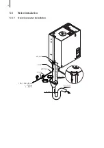
Страница 28: ...28 5 5 Water installation 5 5 1 Overview water installation DS80 125 1250 S cm 1 10 bar 1 40 C 40 mm 10 8 mm G 1 2 Z261 40 mm G 1 2 min 50 cm min 10 min 10...

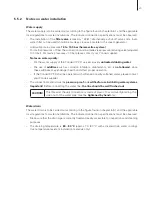
Страница 29: ...not allowed since these additives may endanger health and affect proper operation If the Condair CP3 D shall be operated with softened or partly softened water please contact your Condair supplier Th...

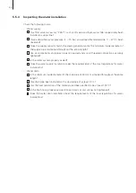
Страница 30: ...d pipes properly secured and are all threaded connections securely tightened Is the water system properly sealed Does the water supply installation meet the requirements of the local regulations for w...

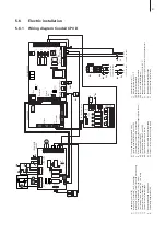
Страница 31: ...team bath option U1 Analogue output temperature 0 10V 0 100 C U2 Analogue output temperature signal for the control of the flap actuator M3 X0 Connection terminal heating voltage X1 Connection termina...

Страница 32: ...ing of 3 mm is an essential requirement and a fuse group F1 essential requirement fuses are to be as detailed in the following table must be installed by the client Heating voltage Max steam capacity...

Страница 33: ...steam bath lighting is connected to terminals X2 3 and X2 4 on the steam bath board accord ing to the wiring diagram Note The cross section of the cable must comply with the applicable local regulatio...

Страница 34: ...ied self adhesive If the type designation on the CP3 Card and the data plate do not match the CP3 Card must not be installed If this is the case contact your Condair supplier 5 6 4 Inspecting the elec...

Страница 35: ...erator must manually be started via the Start Stop button of the display and control unit or via an external Start Stop button or the operation runs time controlled via the day timer or the week timer...

Страница 36: ...aining of the steam cylinder After having pressed the drain key the draining is controlled via the display and control unit Unit switch Function Switches the unit on and off The switch is illuminated...

Страница 37: ...o be switched off because of a malfunction please note the error code of the actual error message shown in the display 2 Close the shut off valve in the water supply line 3 Start manual draining see c...

Страница 38: ...Set Modbus Set Maintenance Set Maintenance Set Esc Esc Set Main Menu Mode Manual Aroma Set Info Set Setpoint 48 C User Set Esc Set 6 4 Overview and operating of the menu The operating and display unit...

Страница 39: ...nerator 5 Actual steam capacity of the unit in kg h 6 Actual request in 7 Actual temperature in the steam bath in C 8 Calculated mean drain time of the unit in seconds 9 Actual status of the maximum l...

Страница 40: ...ed ErrorHistory E32A Temp Sensor void No sensor signal Temp Sensor damaged 01 05 11 11 06 12 34 11 11 2006 12 00 00 Esc Set 6 6 Unit settings 6 6 1 Setting the setpoint temperature Select Setpoint in...

Страница 41: ...s Aroma Interval 5min Impulse 3s Pump On Esc Set Steam Bath Standby CP3 D45 400V3 Temperature 34 C Setpoint 48 C 05 05 2008 12 00 00 Start Menu Light Steam Bath Heating CP3 D45 400V3 Temperature 37 C...

Страница 42: ...etting Note The settings available depend on the current settings of the indi vidual parameters The opposite display shows the maximum number of settings available Description of the steam bath contro...

Страница 43: ...Therefore make sure your settings make sense Fan With the settings in the submenu Fan you can determine the operating mode of the fan as well as the post operational time of the fan for drying the ste...

Страница 44: ...tting range 50 20 C 100V Temp Setting the temperature value in C which equals to 10 V for a 0 10V temperature sensor Note this setting is available only if sensor type 0 10V is selected Factory settin...

Страница 45: ...he steam production is interrupted and the drying phase begins if the fan is activated After the drying phase the light is switched off automatically Factory setting 2 h Setting range 1 24 h Max Door...

Страница 46: ...key to call up the modification dialogue for the selected setting Description of the water management settings Conductivity Selecting the conductivity range of the supply water Factory setting 125 S c...

Страница 47: ...actory setting 72 hours Setting range 1 720 hours Force Drain Activating Deactivating the forced draining which takes place after a cer tain time of operation The forced draining takes place also duri...

Страница 48: ...smission Factory setting None Options None Odd Even Timeout Setting the time out time for the data transmission Factory setting 5 Seconds Setting range 1 600 Seconds Settings Water Manag Set Remote Te...

Страница 49: ...lectrical shock You may get in touch with live parts when the unit is open Touching live parts may cause severe injury or even lethal viola tion Prevention Before carrying out any maintenance work set...

Страница 50: ...move cover and tighten fixing screw with hexagonal head socket wrench Warning This work should only be carried out by an electrician Replacement steam cyl type A X Remove and replace Drain pump X Remo...

Страница 51: ...h the rubber sleeve from the connection in the unit cover and from the steam outlet connection of the steam cylinder Units without steam hose connector in housing top not shown release the hose clamp...

Страница 52: ...steam cylinder into the receptacle and push it down to the stop Attach the electrode plugs and the level sensor plug to the respective electrode and sensor con nections according to the following tab...

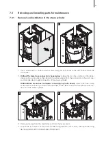
Страница 53: ...lesteamcylinderfollowsthereversesequence Observethe follow ing Before assembling the steam cylinder check the O ring in the steam cylinder cover and the O rings on the electrodes for damage and replac...

Страница 54: ...s Note The hoses connected to the water cup may also be removed together with the water cup see illustration and then disconnected from the connectors of the water cup outside the unit 2 Carefully pul...

Страница 55: ...ump follows the reverse sequence Before as sembling the pump check O ring for damage and replace if necessary Then place the O ring on the centering collar and moisten the O ring with water 7 3 5 Remo...

Страница 56: ...ve safety notes in chapter 7 5 Allow the acid to take effect until the limescale has dissolved Note The heating elements do not have to be entirely free from scale Finally rinse the heating electrodes...

Страница 57: ...ing any cleaning agent CAUTION Takecarethattheelectricalconnectionsand the electronic components remain dry 7 5 Notes on cleaning agents Only use cleaning agents stated in the table above The use of d...

Страница 58: ...ce menu then press the Set key The reset dialogue shows up in the display Press the Yes key to reset the maintenance counter Note Press the No key if you wish to abort the reset procedure To return to...

Страница 59: ...unit or with the basic settings of the control electronics Install correct CP3 Card Let your Condair service technician adjust the basic settings Wrong hardware settings red lights Error E9 Illegal S...

Страница 60: ...iner insert in the inlet valve if applicable clean strainer insert or replace inlet valve Excessive back pressure in the steam line steam line too long or kinked causing water loss via filling cup Ins...

Страница 61: ...team cylinder reset the maintenance counter see chapter 7 6 Steam cylinder needs service Max operating hours of the steam cylinder reached yellow lights Warning W29A Cyl Maintenance red and yellow fla...

Страница 62: ...al installation e g replacement of fuses must be repaired by authorized personnel or by your Condair representative s service technician only Repair work and the replacement of faulty components must...

Страница 63: ...proceed as follows 1 Take the unit out of operation as described in chapter 6 3 2 Have the unit and all other system components if necessary unmounted by a qualified service technician 9 2 Disposal Re...

Страница 64: ...g water with a conductivity of 125 1250 uS cm Admissible water temperature 1 40 C Admissible ambient temperature 1 40 C Admissible ambient humidity max 75 rh Type of protection IP 20 Conformity CE VDE...

Страница 65: ...65 10 2 Unit dimensions Condair CP3 D 5 15 dimensions in mm 456 42 5 178 177 73 28 105 71 28 93 34 40 280 150 228 51 180 90 500 620...

Страница 66: ...66 Condair CP3 D 16 45 Dimensions in mm 559 228 42 5 667 40 28 105 71 175 34 93 350 73 177 284 51 216 144 545 32...

Страница 67: ...Walter Meier Climate International Ltd 2008 Printed in Switzerland Technical modifications reserved...

Страница 68: ...rnational Ltd Talstr 35 37 P O Box CH 8808 Pf ffikon Switzerland Phone 41 55 416 61 11 Fax 41 55 416 62 62 www waltermeier com international climate waltermeier com Consulting Sales and Service Reg No...

Отзывы: