


V30/30 DISTRIBUTION PANEL
SETUP AND OPERATION MANUAL
PAGE 12 - OPERATION
5.3 Module Detail
To access this screen, press any breaker status icon.
5.3.1 Individual breaker Load and Ampacity
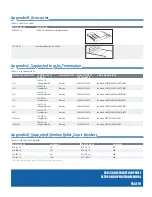
TAbLE 14. bREAKER STATUS
BREAKER COLOR STATUS
Gray
Breaker not installed and if installed, breaker is OFF and not
inventoried
Green
Normal operation and breaker is in inventory
Light Orange
Breaker not inventoried but turned ON (no alarms
monitored)
Orange
Breaker in minor alarm and only monitored for inventoried
breakers (breaker overload warning)
Red
Breaker in major alarm and only monitored for inventoried
breakers (breaker overload or breaker trip)
5.3.2 breaker Detail
Within the module detail menu, the breaker detail menu is accessed by
pressing any breaker icon. Another breaker can be selected in this menu
by pressing the left and right arrow buttons located at the bottom of the
screen.
5.3.2.1 breaker Ampacity:
Breaker ampacity is displayed with a SET button to set breaker ampacity.
Press this to enter the breaker ampacity keypad screen. To enter a new
ampacity for the selected breaker:
1. Use keypad to enter an ampacity between 1A and 35A.
2. Press SAVE button to save ampacity, or CANCEL to revert back
to old ampacity.
5.3.2.2 breaker Load:
Breaker load calibration can be adjusted by pressing the plus and minus
buttons.
5.3.2.3 Alarm Threshold:
Individual breaker alarm threshold is displayed with a SET button to set
breaker alarm threshold. Press this to enter the alarm threshold screen. To
enter a new alarm threshold for the selected breaker:
1. Use keypad to enter an alarm threshold. Alarm threshold range
is between 40% and 100%.
2. Press SAVE button to save threshold, or CANCEL to revert back
to old ampacity.
y
Redundancy can be turned ON/OFF by pressing the check box next
to
Redundancy
. This option is for breaker channel redundancy. If
enabled, the breaker will automatically pair with it's mirror image
position on the adjacent module to the left or the right.
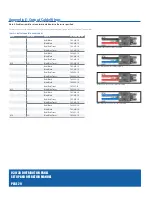
Figure 15. Module Detail
Breaker status
Breaker ampacity
Breaker load
Figure 16. breaker Detail
Содержание v30/30
Страница 1: ...SETUP AND OPERATION MANUAL F O R T E L E C O M B R O A D B A N D v30 30 Distribution Panel...
Страница 3: ...SETUP AND OPERATION MANUAL F O R T E L E C O M B R O A D B A N D v30 30 Distribution Panel...
Страница 6: ...V30 30 DISTRIBUTION PANEL SETUP AND OPERATION MANUAL PAGE vi THIS PAGE INTENTIONALLY LEFT BLANK...
Страница 14: ...V30 30 DISTRIBUTION PANEL SETUP AND OPERATION MANUAL PAGE 8 Installation THIS PAGE INTENTIONALLY LEFT BLANK...
Страница 29: ...THIS PAGE INTENTIONALLY LEFT BLANK...


