V30/30 DISTRIBUTION PANEL
SETUP AND OPERATION MANUAL
PAGE 6 - INSTALLATION
4.5 Alarm Installation
The V30/30 distribution panel includes a Form-C dry alarm contact for remote alarm
monitoring. If alarm monitoring is required, a 8p8c
(
RJ-45) modular jack is provided for
alarm connection.
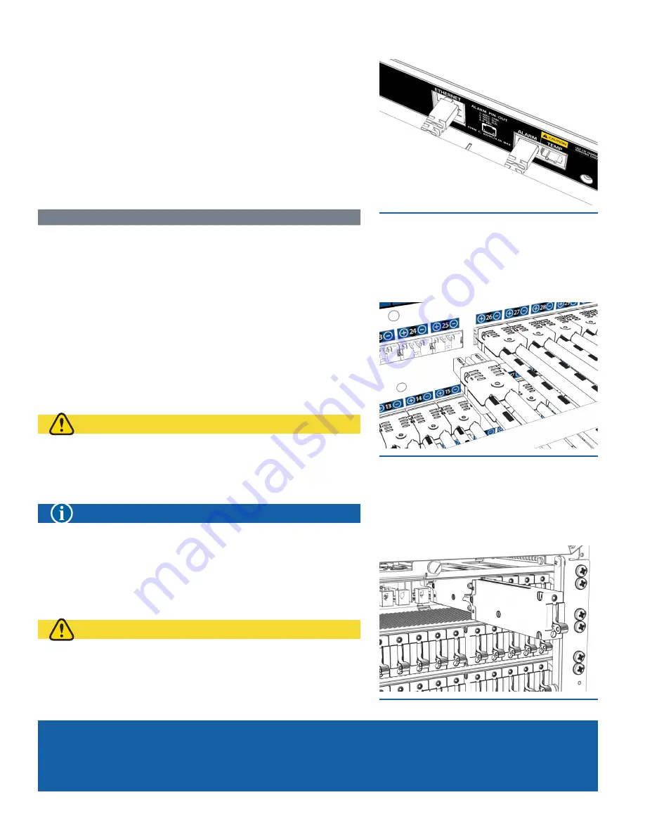
The 8p8c modular jacks are located behind the hinged input bus plastic cover. Refer
to mechanical drawings found in Appendix A for more details.
Step 1.
Plug in a UTP cable with a TIA/EIA T568B termination into the alarm jack
(see
Figure 7)
. Refer to Table 4 for termination pinout information.
Step 2.
Connect the cable to the site alarm monitoring system.
TAbLE 4. ALARM CONTACT PINOUT
PIN 1
PIN 2
PIN 3
PIN 4
PIN 5
PIN 6
PIN 7
PIN 8
Major COM Major NC Major NO Reserved
Reserved Reserved
Reserved Reserved
4.6 Installing the Network Cable
If remote monitoring over the network is required, complete the following steps to
connect the Ethernet module with embedded web server.
NNTTE:
For initial configuration, it is recommended to use a crossover Cat 5/5e/6 UTP
cable to connect a laptop directly to the Tthernet port of the v30/30 panel. If the laptop is
configured for Auto MDI-X, a straight-through cable may be used.
Step 1.
Connect a Cat 5/5e/6 UTP Ethernet cable from the local network to the
Ethernet port on the rear of the panel. Use a TIA/EIA T-568B pinout for the
network connection.
4.7 Output Connections
CAUTION
y
DO NOT PERFORM THIS STEP ON CIRCUITS
WITH bREAKERS INSTALLED.
y
ENSURE NO POWER IS PRESENT ON THE CIRCUIT
bEING CONNECTED bEFORE PROCEEDING.
NOTICE
SEE APPENDIX E ON PAGE 20 FOR CONNECTORIZED
CAbLE WHIP ORDERING INFORMATION.
Step 1.
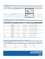
Plug in the output cables to the output connectors on the rear of the panel
(see
Figure 8)
.
4.8 breaker Installation
CAUTION
ENSURE bREAKERS ARE IN THE OFF
POSITION bEFORE INSERTING THEM.
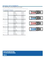
The V30/30 distribution panel offers
(6)
removable breaker modules that each can fit
up to (
10)
slimline breakers.
Step 1.
Insert breakers of sufficient ampacity into place
(see Figure 9)
.
Figure 8. Output Connections
Figure 7. Alarm/Ethernet
Figure 9. breakers
Содержание v30/30
Страница 1: ...SETUP AND OPERATION MANUAL F O R T E L E C O M B R O A D B A N D v30 30 Distribution Panel...
Страница 3: ...SETUP AND OPERATION MANUAL F O R T E L E C O M B R O A D B A N D v30 30 Distribution Panel...
Страница 6: ...V30 30 DISTRIBUTION PANEL SETUP AND OPERATION MANUAL PAGE vi THIS PAGE INTENTIONALLY LEFT BLANK...
Страница 14: ...V30 30 DISTRIBUTION PANEL SETUP AND OPERATION MANUAL PAGE 8 Installation THIS PAGE INTENTIONALLY LEFT BLANK...
Страница 29: ...THIS PAGE INTENTIONALLY LEFT BLANK...


