IE-MLG-M1200E-01
17
Keyboard operation
Control and indication parts
The front panel of the Multilogger includes 6 keys, 3 indication LED diodes
and a graphic display.
The red key with the switch symbol is used for Multilogger turning on/ off.
The MIN/MAX keys (with the arrows) are used for quick show of the
minimal and maximal measured values and also for moving through menu
items. Function of keyboard upper row buttons is defined by actual
description of each button on the lower LCD line display.
The indication LED diodes inform us about the current state of alarms and
allows the operation personnel to observe this important information even
under low light and from a greater distance.
green LED
no active alarms, “everything is OK”
orange LED
one alarm is active
red LED
several alarms are active or a system alarm
(device malfunction)
The green LED (“everything is OK”) can be deactivated in device
configuration to save energy. The indication LEDs can be enabled
permanently or can be set to a blinking mode in battery mode to save
energy also. If the measured quantity has both alarms set into the same
direction, the LED diodes will indicate the current level of value: green -
everything is OK, orange - exceeding the lower limit, red - exceeding the
upper limit.
The LEDs show an overview about all active alarms in the Multilogger. In
the device configuration, we can assign individual alarms to the LED
diodes for customizing the indication to our needs.
Содержание M1200E
Страница 1: ...www cometsystem com Instruction manual M1200E Multilogger ...
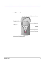
Страница 5: ...IE MLG M1200E 01 5 Multilogger drawing ...
Страница 10: ...10 IE MLG M1200E 01 The way of mounting the holder to Multilogger and mounting holes dimensions MLP001 MLP002 ...
Страница 50: ...50 IE MLG M1200E 01 Appendix 2 Input circuits ...


