IE-MLG-M1200E-01
13
Inputs of Multilloger
Universal input with miniature thermocouple connector:
thermocouples of the K, J, S, B, T and N types
DC Voltage -18 mV to +18 mV
DC Voltage -60 mV to +140 mV
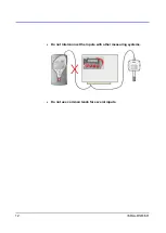
Plug properly oriented connector to the input of Multilogger. The connector
is mechanically coded using a wider pin. Use the white uncompensated
connector for measuring voltage. Make sure that the wires are not connected
to any other conductive parts! Electrical coupling among thermocouples can
cause large measurement errors or instable values! To obtain correct
measurement values, the Multilogger has to be temperature-stabilized!
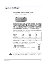
Marking of subminiature thermocouple connectors and wires manufactured
by OMEGA (in accordance with US standard):
Thermocouple type
Connector color
+ wire color
- wire color
K (NiCr-Ni)
Yellow
Yellow
Red
J (Fe-Co)
Black
White
Red
S (Pt10%Rh-Pt)
Green
Black
Red
B (Pt30%Rh-Pt)
White
Black
Red
T (Cu-CuNi)
Blue
Blue
Red
N (NiCrSi-NiSiMg)
Orange
Orange
Red
Two voltage ranges are available on each universal
thermocouple connector for measuring small voltages:
range -60 mV to +140 mV
range -18 mV to +18 mV
Use the white uncompensated connector connected
according to the picture.
The Multilogger does not have galvanically isolated inputs. For this reason,
only devices that are not connected to any other circuit may be connected to
the inputs of Multilogger. Simplified circuit diagram of inputs is shown in
Appendix 2
.
Содержание M1200E
Страница 1: ...www cometsystem com Instruction manual M1200E Multilogger ...
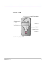
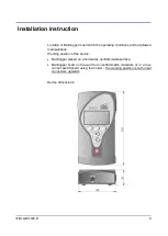
Страница 5: ...IE MLG M1200E 01 5 Multilogger drawing ...
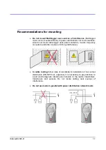
Страница 10: ...10 IE MLG M1200E 01 The way of mounting the holder to Multilogger and mounting holes dimensions MLP001 MLP002 ...
Страница 50: ...50 IE MLG M1200E 01 Appendix 2 Input circuits ...


