


Reflect-O-Ray
®
Oil Fired EDS 3.5
Installation, Operation & Service
Combustion Research Corporation
Page 3
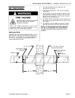
INSTALLATION NOTES
A. GENERAL INSTALLATION LAYOUT
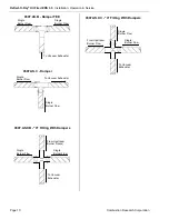
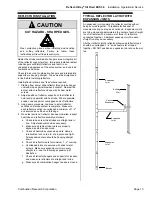
1. Height from floor - 10' to 30' (refer to chart for
recommended minimum mounting heights). There are
no restrictions on the mounting height of the equipment
providing the design is based on the full heat loss of the
building. Consideration must be given to the building
heat loss so as to cover the air infiltration and/or the
mechanical ventilation of the building. For serviceability
and optimum performance the system should be
mounted with careful consideration to the use of the
building.
B. RADIANT TUBE ELEMENT LENGTHS FOR
STANDARD (OIL FIRED OIL FIRED EDS 3.5)
SYSTEMS.
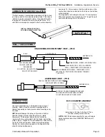
1. To dissipate maximum heat and avoid continuous
condensation in the radiant tube elements, each burner
will be provided with the minimum or maximum tube
lengths as outlined in the following chart. A heavy walled
16 gauge aluminized steel tube (10' -0") long is used
adjacent or downstream of each burner. The remainder
of the radiant tubing shall be of spiral wound aluminized
steel tube. Each single flow of radiant tube shall
incorporate an adjustable damper for regulating burner
airflow.
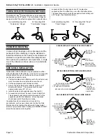
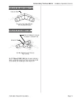
2. A multiple burner system consists of two or more
burners. Refer to the following charts for radiant tube
lengths and elbow and tee placement.
C. RADIANT TUBE ELEMENT LENGTHS FOR HIGH
OUTPUT (OIL FIRED OIL FIRED EDS 3.5) SYSTEMS.
1. To dissipate maximum heat and avoid continuous
condensation in the radiant tube elements, each burner
will be provided with the minimum tube lengths as
outlined in the following chart. A heavy walled 16-gauge
aluminized steel tube 10' 0" long is used adjacent to
each burner. The remainder of the radiant tubing shall be
of spiral wound aluminized steel tube. Tee's must be
installed after any turbulator tube. Each single flow of
radiant tube shall incorporate an adjustable damper for
regulating burner airflow. NOTE: The radiant tubes for
the
Reflect-O-Ray
®
OIL FIRED EDS 3.5
systems can
and may be heat treated for optimum heat transfer.
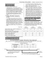
DESIGN TUBE LENGTH REQUIREMENTS
FOR OPTIMUM EFFICIENCIES
The dimensions in the table listed below are basic
guidelines used in the design of the
Reflect-O-Ray
®
Oil Fired
OIL FIRED EDS 3.5
systems. Every effort should be made
to hold the dimensions given on the layout drawing. The
factory should verify any deviations from the layout drawing
or for alternate and/or customized layouts.
Burner Type
0500.R
125,000 Btu/hr
0510.R
105,000 BTU/HR
0520.R
70,000 Btu/hr
Standard Output System – Radiant Tube Between Any
Burner & Vacuum Exhauster
90’
70’
80’
60’
70’
50’
High Output (Reduced Tube Length) Systems
80’
60’
70’
40’
60’
40’
Maximum Flows Through One Radiant Tube
2
3
4
Minimum Distance Before Elbow
30’
25’
20’
Minimum Distance Before Tee
40’
40’
30’
Minimum Distance Before Damper
30’
30’
30’
* - Distances used with 0304.INSL radiant tube assemblies.
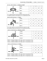
VACUUM EXHAUSTER SELECTION
Recommended Maximum Number of Burners Per Vacuum Exhauster
Note: The factory must be consulted for any deviations to the basic design criteria listed below. Burner inputs
may be mixed with each system (vacuum exhauster).
BURNER ASSEMBLIES
Vacuum Exhauster
0500.R
0510.R
0520.R
0402.WO/DI
4
4
6
0401.WO/DI
3
4
4
0201.WO
2
2
2
*40’
* 40’
Burner
Burner
40’
10’
40’ + 10’ + 40’ = 90’ From Vacuum Exhauster to either burner
* - In multiple burner systems the radiant
tubing runs do not have to be equal or
balanced in length.
Vacuum
Exhauster
Содержание reflect-o-ray eds 3.5
Страница 4: ......
Страница 57: ...Reflect O Ray Oil Fired EDS 3 5 Installation Operation Service Combustion Research Corporation Page 53 NOTES...
Страница 60: ......
Страница 61: ......