


Reflect-O-Ray
®
Oil Fired EDS 3.5
Installation, Operation & Service
Page 22
Combustion Research Corporation
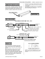
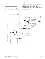
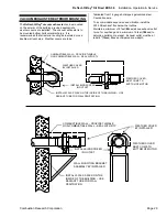
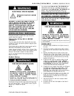
FLEXIBLE OIL CONNECTOR
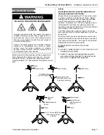
WARNING
FIRE OR EXPLOSION HAZARD
IMPROPER INSTALLATION, ADJUSTMENT,
ALTERATION, SERVICE OR MAINTENANCE
CAN CAUSE DEATH, SEVERE INJURY
AND/OR PROPERTY DAMAGE.
There Is expansion of the radiant pipe with each firing
cycle and this will cause the burner to move with
respect to the oil supply line. This can cause an
unsafe condition if the oil pipe connection is not done
in strict accordance to the instructions.
Install the flexible oil hose as shown in the diagram below.
This flexible connector accommodates the normal
expansion of the system. Before attaching the oil
connector verify that any high-pressure testing has been
completed.
•
Do not high pressure test the oil piping with the burner
connected. Failure to follow these instructions can result
in property damage.
•
Check the pipe and tubing ends for leaks before placing
heating equipment into service. The loop of the oil
supply flex MUST BE parallel or in line with the oil
burner itself.
•
The displacement as shown is for cold, non-firing
condition. This displacement will vary as system heats
up.
•
Install fusible link valve in both the supply and return
lines in accordance with all applicable codes.
•
Install a fuel filter at each burner assembly as well as at
the oil supply source.
•
ALWAYS USE TWO (2) WRENCHES WHEN MAKING
PIPING CONNECTIONS TO THE BURNER.
•
DO NOT APPLY PIPE DOPE TO FLARE NUT
FITTINGS OF THE FLEXIBLE CONNECTOR
.
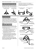
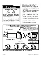
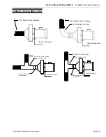
Burner Assembly End View
Burner Assembly Side View
Burner Movement
INCORRECT POSITIONS
Hold oil fittings securely with
wrenchs when connecting
flexible Oil Hose and fittings.
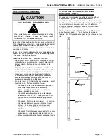
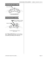
2” – 3” (5 – 7.6cm)
Cold Displacement
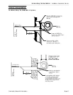
The Fusible Shut-Off Valve and oil filter must be
parallel with the burner as well as the first section
of radiant tube. A 2” (5 cm) cold displacement for
initial setup is shown. This displacement can
reduce when the system is fired.
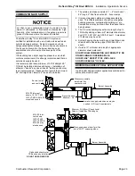
Flexible Oil Hose – Form connector
into a lazy “U” bend as shown. DO
NOT make sharp bends
.
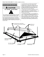
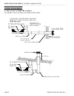
For descriptive purposes, only the Oil Inlet is shown in this illustration. The
Oil Return line shall be installed in the same manner.
Use 36” long steel braided flexible rubber oil hose with 3/8” MPT ends for connections
!
Содержание reflect-o-ray eds 3.5
Страница 4: ......
Страница 57: ...Reflect O Ray Oil Fired EDS 3 5 Installation Operation Service Combustion Research Corporation Page 53 NOTES...
Страница 60: ......
Страница 61: ......