


Reflect-O-Ray
®
Oil Fired EDS 3.5
Installation, Operation & Service
Page 14
Combustion Research Corporation
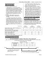
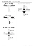
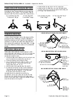
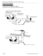
TUBE & REFLECTOR HANGING METHODS
The
Reflect-O-Ray
®
System reflectors can be suspended
horizontally or at a 30° angle. The combination hanger is
designed so that the reflector angle will be horizontal when
suspended from the top loop or at a 30° angle when
suspended from the offset loop – see the illustration below.
The panel hangers may also be suspended horizontally or at
a 30° angle – see illustration below.
Horizontal Mounting With
“Combination” Hanger
30° Mounting With
“Combination” Hanger
Horizontal Mounting With
“Panel” Hanger
30° Mounting With “Panel”
Hanger
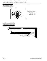
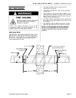
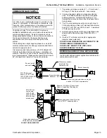
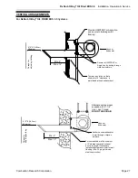
PERIMETER MOUNTING
In areas of high heat loss such as doorways and the
perimeter of some buildings, it may be desirable to
install the reflectors so that heat is concentrated and
directed to a specific area rather than straight down.
Two options are available to accomplish this, 1) angle
mount the reflector as shown above or 2) install side
shields.
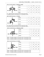
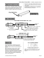
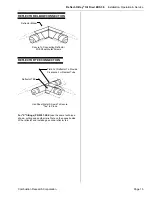
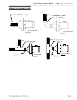
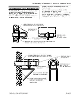
SIDE SHIELD INSTALLATION
Optional side shield reflectors may be installed on either
side or both sides of the reflector. The 10-ft. (3 m) long side
shields should line up with a reflector and have identical
overlap and expansion joints.
1. Position the side shield reflector next to the reflector, and
mark the areas where relief notches must be cut.
2. Cut the appropriate relief notches as noted.
3. Secure the side shield to the reflector with #8 x 3/8"
sheet metal screws. The screws should be used
approximately every 24" (61 cm).
4. Install the side shield supports every five feet (5’)
5. An expansion joint must be used in each straight run.
This expansion joint should match the location of the
expansion joint for the reflectors. All overlap areas
should also match the reflector overlap.
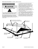
In applications where excessive air movement is
encountered, such as open doors and the like, the Side
Shields should be fastened together with 2 sheet metal
screws or pop rivets at each overlap joint.
NOTE:
DO NOT
screw the expansion joints together.
FIELD FAB
RELIEF NOTCH
IN SHIELD
SECURE WITH
S/M SCREW
SECURE SIDE
SHIELD HANGER
WITH S/M SCREW
SECURE SIDE
SHIELD SUPPORT
(P/N 0368.00) TO
TUBE WITH S/M
SCREW
0367.00
SIDE SHIELD
0360.00 REFLECTOR & 0367.00 SIDE SHIELD
FIELD FAB
RELIEF NOTCH
IN SHIELD
SECURE WITH S/M SCREW
SECURE
SIDE SHIELD
HANGER WITH
S/M SCREW
SECURE SIDE SHIELD
SUPPORT (P/N 0368.0010)
TO TUBE WITH S/M SCREW
0367.00
SIDE SHIELD
0812.00 REFLECTOR & 0367.00 SIDE SHIELD
FIELD FAB
RELIEF NOTCH
SECURE WITH
S/M SCREW
SECURE
SIDE SHIELD
HANGER WITH
S/M SCREW
SECURE SIDE
SHIELD SUPPORT
(P/N 0366.0050)
TO TUBE WITH
S/M SCREW
0366.00
SIDE SHIELD
0363.00 REFLECTOR & 0366.00 SIDE SHIELD
Содержание reflect-o-ray eds 3.5
Страница 4: ......
Страница 57: ...Reflect O Ray Oil Fired EDS 3 5 Installation Operation Service Combustion Research Corporation Page 53 NOTES...
Страница 60: ......
Страница 61: ......