


Reflect-O-Ray
®
Oil Fired EDS 3.5
Installation, Operation & Service
Combustion Research Corporation
Page 1
WARNING SYMBOLS
WARNING
Warning
indicates a potentially hazardous situation which, if
not avoided, could result in death or injury.
CAUTION
Caution
indicates a potentially hazardous situation which, if
not avoided, could result in minor or moderate injury.
NOTICE
Notice
indicates a potentially hazardous situation which, if
not avoided, could result in property damage.
CHECKING SHIPMENT
Upon receipt of shipment, check shipment against Bill of
Lading for shortages. Also check for external damage to
cartons or tube bundles. Shortages and/or external damage
to cartons or tubes must be noted on the Bill of Lading in the
presence of delivery trucker. The delivery trucker should
acknowledge any shortages or damage by initialing this
"noted" Bill of Lading.
Claims for damaged material, or shortages that were not
evident upon receipt of shipment must be reported to carrier
and Combustion Research Corporation Sales
Representatives within 72 hours.
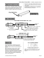
Before starting to assemble the heater, make sure
that all optional and accessory items are accounted
for and are available for assembly. It is also important
to verify that the correct Btu input burner is supplied
for the project.
IMPORTANT
WARNING
FIRE HAZARD
IMPROPER INSTALLATION CAN
CAUSE DEATH, SEVERE INJURY
AND/OR PROPERTY DAMAGE.
Read and understand these installation, operating and
maintenance instructions thoroughly before installing or
servicing this equipment. Only trained, qualified fuel oil
installation and service personnel may install or service
this equipment.
These instructions, the layout drawing, local codes and
ordinances, and applicable standards such as apply to oil
piping and electrical wiring must be thoroughly understood
before proceeding with the installation.
TESTED UNDER STANDARDS
AMERICAN STANDARDS
– UL 731-1995
CANADIAN STANDARDS
– CAN
/
CSA B140.04-04
BUILDING CODES
In the absence of local codes, the installation must conform
to the latest edition of:
United States:
National Fuel Gas Code, ANSI Z223.1
(NFPA 54).
Canada:
CAN/CGA B149.1 & .2 and the Canadian Electrical
Code C22.1
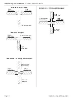
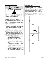
AIRCRAFT HANGERS
Heaters for use in aircraft hangers must be installed in
accordance with;
United States:
Refer to Standard for Aircraft Hangars,
ANSI/NFPA 409 (latest edition).
In Canada:
Refer to Standard CAN/CGA B149.1 and
B149.2 and applicable Standards for Aircraft Hangars.
Basic guidelines are as follows:
1. Suspended heaters in aircraft storage or service areas
shall be installed at least ten feet (10') above the upper
surface of wings or engine enclosures of the highest aircraft
which may be housed in the hanger. This should be
measured from the bottom of the heater to the wing or
engine enclosure, whichever is highest from the floor.
2. In other sections of aircraft hangers, such as shops or
offices communicating with airplane storage or servicing
area, heaters shall be installed in accordance with their
listings and mounted not less than eight feet (8') above the
floor.
3. Heaters installed in aircraft hangers shall be located so as
not to be subject to injury by aircraft, cranes, moveable
scaffolding or other objects. Provisions shall be made to
ensure accessibility to suspended heaters for recurrent
maintenance purposes.
PUBLIC GARAGES
Heaters for use in public garages must be installed in
accordance with:
United States:
Standard for Parking Structures NFPA 88A
(latest edition) or the
Code for Motor Fuel Dispensing
Facilities and Repair Garages NFPA 30A (latest
edition).
Canada:
Refer to CAN/CGA B149.1 and B149.2: Installation
Codes and applicable Standards for Public Garages.
Basic guidelines are as follows:
1. Heaters shall be installed in accordance with their listings
and not be mounted less than eight feet (8') above the floor.
Minimum clearances to combustibles must be maintained
from vehicles parked below the heater.
2. When installed over hoists, clearance to combustible
material must be maintained from upper most point of the
hoist, or provided as insulating or reflective barrier on the
hoist (consult representative or factory for guidance).
!
!
!
Содержание reflect-o-ray eds 3.5
Страница 4: ......
Страница 57: ...Reflect O Ray Oil Fired EDS 3 5 Installation Operation Service Combustion Research Corporation Page 53 NOTES...
Страница 60: ......
Страница 61: ......