Combustion Research reflect-o-ray eds 3.5 Скачать руководство пользователя страница 27

Reflect-O-Ray

®

 Oil Fired EDS 3.5    

Installation, Operation & Service

Combustion Research Corporation 

Page 23

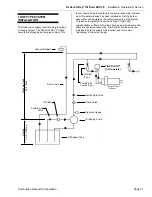
COMBUSTION AIR SUPPLY

4

NOTICE

Air that is not contaminated must be ducted to the
heater if chlorinated or fluorinated contaminants, high
humidity, other contaminants, or if negative pressure is
present in the area where the heater is installed.

The 

Reflect-O-Ray

®

 OIL FIRED EDS 3.5 

system is

certified for installation with use of inside air as well as an
outside air supply system.  Some compounds such as
halogenated hydrocarbons or other corrosive chemicals in
the air can be drawn into the burner and cause an
accelerated rate of corrosion of various parts of the
system.

If the building has a slight negative pressure or air which
contains contaminants it is strongly recommended that an
outside air supply be used.

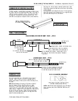
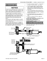
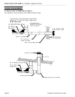
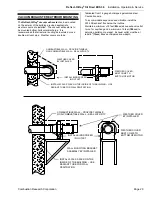
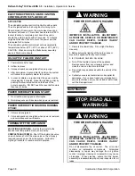
It is recommended that a minimum of 48" of straight 4.0"
OD inlet be installed before each burner.  Installation of
elbows or "bends" any closer than 48" before each burner
is not recommended.  If space will not permit the minimum
48" of straight inlet, install a 4" tee as shown below.

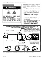
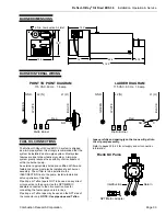
1.  The outside air intake consists of: 1 – 4” Inlet hood, 1 -

24" long 4.0" Dia. flex duct and 2 - hose clamps.

2.  It is recommended outside air intake assembly be

used.  This offsets problems of positive or negative
building pressures, contaminated building air, etc.
Combustion air may be drawn from the space that is
being heated.

3.  The 4” duct assembly may extend in length of up to

100 feet by adding minimum 6" diameter sheet metal
duct (P.D. 0.35" W.C. per l00 ft. of duct).  A maximum
of 3 elbows may be used.

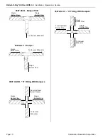
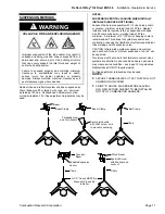
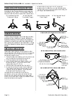
4.  System hanging chains must hang straight down and

chain shall be closed loop type (CM Chain #3, or
equal).

5.  If wall is 10" or thicker, add length of appropriate

diameter sheet metal duct.

DO NOT DRAW COMBUSTION AIR FROM ATTIC OR
OTHER SIMILAR CONFINED SPACE.
DO NOT USE "DRYER" TYPE VINYL FLEX.
DO NOT EXCEED 24" OF FLEX.

BROODER &AGRICULTURAL APPLICATIONS

In all brooder and agricultural applications outside air for
combustion must be used.
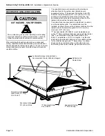
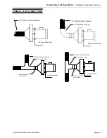
Secure to wall
and caulk

Whenever possible,
install inlet flex
nearest to wall

Recommended

Minimum - 36"

Installer to supply extension as may be
needed – OD to suit requirements.

Burner Assembly

0314.00 Inlet vent
shown.  1810.VT.400,
1810.VT.600 & 0614.00
may also be used.

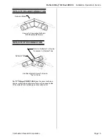
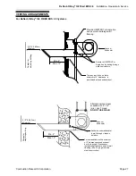
When used as an elbow, form flex
into a "SOFT" sweeping elbow

Galvanized sheet metal

TEE and cap by installer.

DO NOT USE AN ELBOW

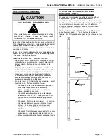
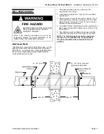
Minimum 2-ft (60 cm) Check Local
Codes - (Install Roof Flashing As
Required)

0314.00 Inlet
vent shown.
1810.VT.400,
1810.VT.600 &
0614.00 may
also be used.

Burner Assembly

Содержание reflect-o-ray eds 3.5

Страница 1: ...ed qualified gas installation and service personnel may install or service this equipment FOR YOU SAFTEY If you have a Fuel Oil leak 1 Open windows 2 DO NOT try to light any appliance 3 DO NOT use ele...

Страница 2: ...am clamps rod or perforated strap and turnbuckles at predetermined locations The weight and normal movement of the heating system may cause support failure if the following minimum suspension requirem...

Страница 3: ...2 Combustion Air 23 Vacuum Exhausters 24 Exhaust Flex Connections 25 Venting 26 29 Electrical Wiring Control Panels 30 32 Burner Wiring Schematic 33 Burner Technical Setup Data 34 Sequence Of Operatio...

Страница 4: ......

Страница 5: ...ce of local codes the installation must conform to the latest edition of United States National Fuel Gas Code ANSI Z223 1 NFPA 54 Canada CAN CGA B149 1 2 and the Canadian Electrical Code C22 1 AIRCRAF...

Страница 6: ...fy the maximum stacking height so as to maintain the required clearance to combustibles GENERAL CONSIDERATIONS Combustion Research Corporation Factory Representatives are experienced in the applicatio...

Страница 7: ...A heavy walled 16 gauge aluminized steel tube 10 0 long is used adjacent to each burner The remainder of the radiant tubing shall be of spiral wound aluminized steel tube Tee s must be installed afte...

Страница 8: ...mended that the system not be mounted lower than 9 from the floor unless fitted with protective screens The following illustrations and information give minimum acceptable clearance to combustibles Mi...

Страница 9: ...be is used B Clearances bottom can be reduced to 15 25 downstream of burner 0363 00 or 0363 02 Reflector HORIZONTAL MOUNT MODEL A B C D 0500 R 7 72 42 42 0510 R 6 72 30 56 D A B C 0520 R 6 72 30 56 05...

Страница 10: ...ation Service Page 6 Combustion Research Corporation INVERTED REFLECTOR 0360 00 or 0360 02 Reflector With an Inverted 0360 00 or 0360 02 Reflector Applies To All Inputs 4 Gap 40 40 5 22 U BEND END CLE...

Страница 11: ...and pre assemble suspension components NOTE Each Reflect O Ray OIL FIRED EDS 3 5 burner assembly is equipped with a suspension point Adjust as required to keep the burner assembly level and square to...

Страница 12: ...the radiant tube at dimensional support locations as outlined in this manual Combination hangers should be position so that The locking loop 45 suspension point face the same direction Combination han...

Страница 13: ...TUBE 5 EXTENSION TUBE 16 GA ALUMINIZED STEEL COMPONENT OF P N 0304 INSL 25 0507 00 DRAWBAND COUPLER COMPONENT OF P N 0304 INSL 25 POSITION BOLT ASSEMBLY TOWARDS THE FLOOR BURNER FLOW ASSEMBLED VIEW T...

Страница 14: ...acuum Exhauster Single Burner Flow 0307 AS C Damper Single Burner Flow To Vacuum Exhauster Single Burner Flow 0307 AS XB X Fitting With Dampers To Vacuum Exhauster From Upstream Burner Flow s Single B...

Страница 15: ...in or greater minimum working load of 200 lbs Radiant tube and reflector system is to be suspended with trade size 3 chain or heavier working load of 90 lbs minimum A minimum of 12 30 cm of hanging ch...

Страница 16: ...ND APPLICATIONS In high wind conditions it is recommended that seismic restraints and reflector retention wire be installed See details below for recommended installation of seismic restraint and anti...

Страница 17: ...on this page 4 When last section of reflector has been installed inspect heat tube and reflector assembly as follows a Check to be sure all heat tubes are straight and in line Adjust suspension when...

Страница 18: ...1 Position the side shield reflector next to the reflector and mark the areas where relief notches must be cut 2 Cut the appropriate relief notches as noted 3 Secure the side shield to the reflector...

Страница 19: ...o Connecting Reflector With Sheet Metal Screws REFLECTOR TEE CONNECTION Use Sheet Metal Screws To Secure Tee In Place Field Cut Reflector To Provide Clearance For Radiant Tube Reflector TEE For X fitt...

Страница 20: ...tile The decorative grill should extend completely under all of the radiant tube as well as the burner assembly The radiant tube is suspended in normal fashion centered over the decorative grille The...

Страница 21: ...ust be a minimum of 25 downstream of the burner 2 A wall thimble suitable for 6 Type B vent or better must be used 3 Use an all steel 6 type B vent duct or better The 6 vent assembly must extend a min...

Страница 22: ...he draw band coupler provided DO NOT APPLY SEALER TO THIS CONNECTION Position bolting assembly on the top of the tube assembly as shown After tightening the coupler check to make sure the burner is li...

Страница 23: ...s to be preformed by a qualified licensed contractor who is familiar with liquid fuel burning systems To insure a proper and smooth operating installation deviations from the recommendations should be...

Страница 24: ...pipe systems Install suitable oil filters before the oil supply pump and secondary filters at each burner assembly Fusible link oil valves must be installed in both the supply side suction and return...

Страница 25: ...assemblies can operate as the recommended two pipe system This device is marketed under the name of Tiger Loop Install suitable oil filters before the oil supply pump and secondary filters at each bur...

Страница 26: ...parallel or in line with the oil burner itself The displacement as shown is for cold non firing condition This displacement will vary as system heats up Install fusible link valve in both the supply...

Страница 27: ...se clamps 2 It is recommended outside air intake assembly be used This offsets problems of positive or negative building pressures contaminated building air etc Combustion air may be drawn from the sp...

Страница 28: ...rmally protected 7 15 16 5 9 16 4 1 8 10 1 1 6 7 3 8 5 3 4 6 1 3 6 2 7 8 Approx 9 5 Approx 19 5 8 0201 WO VACUUM EXHAUSTER DATA 0201 WO 1 4 HP 115 208 230V 3 6 3 0 3 0 FLA 60 Hz 1 Ph 3450 RPM totally...

Страница 29: ...25 PN 0334 SS Flex Clamps Vacuum Exhauster PN 0306 AS 90 Elbow EXHAUST FLEX CONNECTIONS PN 0334 SS Flex Clamps Vacuum Exhauster PN 0334 SS Flex Clamps Vacuum Exhauster PN 0307 AS TEE Secure with sheet...

Страница 30: ...hall not be less than 7 ft 2 1m above grade Vent opening must be beyond any combustible overhang Any portion of the flue pipe that passes through combustible material of the building must have a minim...

Страница 31: ...s Trim any insulation so that a minimum of 2 clearance is maintained around exhaust duct Parapet or adjoining building 6 0 9 183 cm Minimum Min 2 Max 12 Alternate ceiling mount suspend with 4 1 4 min...

Страница 32: ...um Exhauster Square to round adapter 12 30 cm Min 18 45 cm Max Use B vent for wall penetration 1 4HP and Larger Vacuum Exhausters Suspend with a Quantity of 4 1 4 min ALL Thread Length to Suit DO NOT...

Страница 33: ...ex below the roofline Maintain a minimum of 3 feet 92cm above exhaust outlet to roof or overhang and a minimum of 6 feet 184cm to adjoining building or parapet Exhaust outlet must be at least 6 15cm a...

Страница 34: ...ect O Ray OIL FIRED EDS 3 5 system it is essential that the voltage to the exhauster motor and burner controls is sufficient It must be within 10 percent of the nameplate rating under all conditions t...

Страница 35: ...5484 00 Thermostat Contact rating 9 8 amps 24 VAC to 115 V A C BASIC SYSTEM HOOK UP WARNING FIRE OR EXPLOSION HAZARD IMPROPER INSTALLATION ADJUSTMENT ALTERATION SERVICE OR MAINTENANCE CAN CAUSE DEATH...

Страница 36: ...The pre purge and post purge cycles will provide in excess of 12 additional air changes within the combustion chamber and the radiant tubing network The line voltage thermostat will prevent the system...

Страница 37: ...pe system greatly reduces the possibility of air entrapment within the burner pump An external appropriately listed and certified oil filter and fusible link valves must also be installed at each burn...

Страница 38: ...iagram below The following chart shows two types of Riello burner heads The MECTRON 3 M3 head was used prior to the 93 94 heating season and the Riello 40 F3 series is used thereafter BURNER PART NO B...

Страница 39: ...igher temperatures 5 Protect the power cable from coming in contact with sharp objects 6 Do not kink power cable and never allow the cable to come in contact with oil grease hot surfaces or chemicals...

Страница 40: ...park will ignite the oil 5 Check all burners to see that they are operating Flame should be visible through the view window 6 Set the thermostat down to the desired temperature 7 When the system is in...

Страница 41: ...specifically designed and manufactured for the Reflect O Ray OIL FIRED EDS 3 5 system Use of substitute materials can result in an unsafe condition and will void any and all warranties DIAGNOSIS AND...

Страница 42: ...ergized 2 Valve and spark are energized when power is restored and normal sequence will resume TURNING OFF THE APPLIANCE VACATION SHUTDOWN Set the thermostat to the desired room temperature while you...

Страница 43: ...ng installation several complete operating cycles should be observed to see that all components are functioning properly 1 Before turning on the main electrical power switch be sure all oil supply lin...

Страница 44: ...head as shown INSERTION A Slide the complete drawer assembly into the combustion head as shown B Connect the flared oil nut 8 to the oil pump tighten securely C Replace the air tube cover plate 5 and...

Страница 45: ...ning of the air intake To adjustment the manual AIR ADJUSTMENT PLATE 4 loosen the FIXING SCREWS 3 5 The setting of the air adjustment plate is listed on page 34 The proper number on the manual AIR ADJ...

Страница 46: ...the O Ring is properly seated in the PUMP HOUSING 4 before tightening the pump cover Pinching or damaging the O Ring will result in an oil leak Connect the pipe connector to the SUCTION PORT 7 of the...

Страница 47: ...als Is there 120 volts to the pressure switch NO Replace motor NO Is blower obstructed YES Remove obstruction and realign blower wheel YES YES Is the vent pipe air inlet or vacuum exhauster wheel bloc...

Страница 48: ...gas pressure at the manifold pressure tap NG 3 5 LP 10 0 Check gas orifice for blockage proper size YES Replace gas valve NO Adjust supply gas pressure to proper levels see name plate YES Repair or re...

Страница 49: ...5 401 08 9 3 16 Diameter Exhauster Wheel Stainless Steel 6 1032 03 5 16 x 18 Set Screw Provided with exhauster wheel 7 401 06 Vacuum Exhauster Housing 8 1463 31 25 x 1 1 4 Stand Off 9 1122 01 5 16 Pla...

Страница 50: ...5 201 08 9 3 16 Diameter Exhauster Wheel Stainless Steel 6 1032 03 5 16 x 18 Set Screw Provided with exhauster wheel 7 201 06 Vacuum Exhauster Housing 8 1463 31 25 x 1 1 4 Stand Off 9 1122 01 5 16 Pl...

Страница 51: ...Used on 0500 R 125 000 Btu Hr Burner 2 5060 03C Differential Pressure Switch All Models 1 3 1264 24 C Handy Box Cover 2 x 4 1 3 1264 24 Electrical Handy Box 2 x 4 1 4 500 103 A Combustion Can With Fl...

Страница 52: ...Reflect O Ray Oil Fired EDS 3 5 Installation Operation Service Page 48 Combustion Research Corporation REPLACEMENT PARTS Riello 40 F3 Series 49 Electric Air Damper Hydraulic Air Damper...

Страница 53: ...Sub Base 1 19 3006553 Coil U Bracket Retainer Nut 1 20 3002279 Coil 1 21 3007802 Pump 1 22 3000443 Pump Drive Key 1 23 300C700104 Motor 1 24 3007315 Air Tube Cover Plate 1 25 3002280 Photo Cell 1 26...

Страница 54: ...e wall or B Vent Wt 0 75 lbs 1811 VT 600 ROOF OR WALL VENT 6 diameter High Wind mushroom style round vent For B vent Wt 0 75 lbs 5484 00 THERMOSTAT Line voltage 9 8 FLA 50 F to 90 F Wt 1 0 lbs SUNNE 5...

Страница 55: ...UMINIZED STEEL 3 5 dia aluminized steel radiant tube 19 6 long Wt 22 lbs 0311 AS TUBE COUPLER ALUMINIZED STEEL 3 5 dia Wt 1 5 lbs 7 75 0306 AS 90 ELBOW ALUMINIZED STEEL 3 5 dia aluminized steel 90 elb...

Страница 56: ...at tube deep dish reflector hanger for 3 5 tube plated 1 4 dia wire Wt 0 75 lb 0365 00 DEEP DISH REFLECTOR SUPPORT Intermediate support for deep dish reflector for 3 5 tube plated 1 4 dia wire Wt 0 75...

Страница 57: ...Reflect O Ray Oil Fired EDS 3 5 Installation Operation Service Combustion Research Corporation Page 53 NOTES...

Страница 58: ...ly IN NO EVENT SHALL CRC BE LIABLE FOR SPECIAL INDIRECT CONSEQUENTIAL OR INCIDENTAL DAMAGES OF ANY TYPE OR DESCRIPTION WHETHER ARISING UNDER CONTRACT WARRANTY TORT NEGLIGENCE STRICT LIABILITY OR ANY O...

Страница 59: ...the appropriate courts maintaining jurisdiction over all controversies in the State of Michigan VOIDING OF WARRANTIES Each of the following listed events conditions acts or omissions by any person or...

Страница 60: ......

Страница 61: ......

Страница 62: ...COMBUSTION RESEARCH CORPORATION 2516 Leach Road Rochester Hills Michigan 48309 3555 Telephone No 248 852 3611 www combustionresearch com...

Отзывы: