62
MAINTENANCE
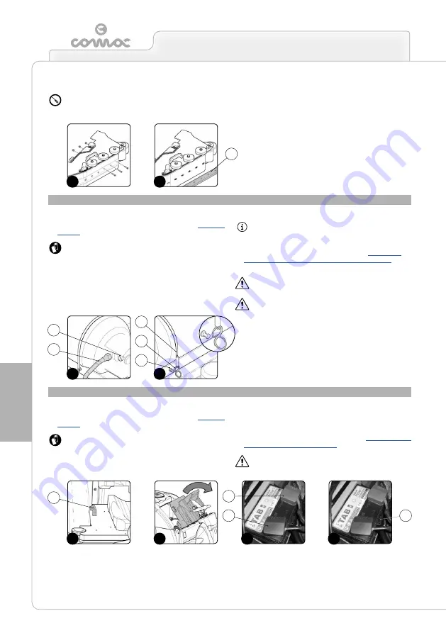
REPLACING THE LPG CYLINDER (G VERSIONS)
To replace the LPG cylinder when it is empty, proceed as follows:
1. Make sure the machine is in a safe condition (read “
ATTENTION:
these operations must be carried out using
protective gloves to avoid any possible contact with the edges
or tips of metal objects.
2. Disconnect the LPG supply tube (1) from the valve (2) in the
cylinder (
Fig.1
).
3. Free the cylinder from its support by releasing the spring (3)
in the retainer blade from the screw (4) in the support (
Fig.2
).
Remove the cylinder retainer blades (5).
4. Remove the cylinder from its support.
ATTENTION
: you are advised to only lift and move the LPG
cylinder with lifting and transportation means suitable for the
specific weight and size.
5. Replace the old cylinder with a new one. Read “
THE LPG CYLINDER IN THE MACHINE (G VERSIONS)
” to
understand the correct assembly phases.
ATTENTION
: remember to also replace the seal on the valve
in the cylinder.
ATTENTION
: this operation must be carried out by a
specialised technician.
REPLACING THE STARTER BATTERY (G VERSION)
To replace the starter battery, proceed as follows:
1. Make sure the machine is in a safe condition (read “
ATTENTION:
these operations must be carried out using
protective gloves to avoid any possible contact with the edges
or tips of metal objects.
2. Grip the handle (1) (
Fig.1
) and raise the seat mounting plate to
the maintenance position (
Fig.2
).
3. Disconnect the positive (+) cable from the starter battery (
Fig.3
).
4. Disconnect the negative (-) cable from the starter battery (
Fig.3
).
5. Release the battery retainer (2) (
Fig.4
).
6. Replace the old battery with a new one. Read “
”.
ATTENTION
: this operation must be carried out by a
specialised technician.
7.
Use the appropriate tool to remove the screws (7) that fix the
rubber-pressing blade (8) to the brush head splash guard support
(
Fig.5
).
ATTENTION
: the equipment to be used for this operation is
not supplied with the machine.
8. Remove the rubber-pressing blade (8) (
Fig.6
).
9. Remove the splash guard rubber and replace it
10. Repeat the operations in reverse order to reassemble all the
parts.
11. Repeat steps 4 - 10 on the left-hand side of the machine.
1
2
3
4
1
2
5
6
1
1
2
3
3
3
4
8
2
5
Содержание ULTRA 120 B-G
Страница 2: ......
Страница 7: ...7 36 72 102 6 9 10 110 107 106 75 5 76 74 58 7 59 7...
Страница 8: ...8 100 74 28 29 67 48 49 47 37 38 39 16 82 87 77 86 81 85 78 84 50 79 88 51 80 89 90 83 25 62 61 39 14...
Страница 9: ...9 103 4 56 31 43 109 15 3 98 22 65 24 108 19 34 35 23 68 44 63 64 99...
Страница 10: ...10 2 94 17 101 96 105 69 12 11 18 73 40 97 95 104 42...
Страница 68: ...68 NOTES...
Страница 69: ...69 NOTES...
Страница 70: ...70 NOTES...
Страница 71: ......


