background image


Page 

5

 of 

40


FABJET GRAND 

 2. Machine Overview 

Front View 

The 

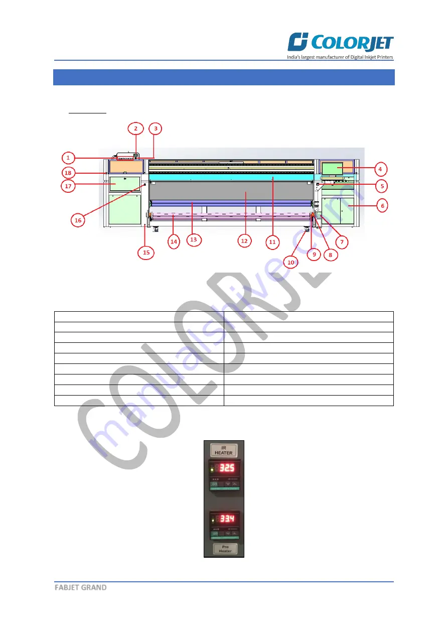
Front View

 of the machine is shown in the image below: 


Fig 1: Displaying the Front View 

Table 1: Different Parts of the Machine 

1.


Ink Valves 

2.


Head Height Meter  

3.


Negative Pressure Meter 

4.


LCD Panel 

5.


Print Dryer Controller 

6.


Electric Housing Cabinet 

7.


Take Up Motor 

8.


Take Up Sensor 

9.


Safety Chuk 

10.


Wheel 

11.


Front Panel 

12.


Print Dryer 

13.


Guiding Roller 

14.


Take Up/Air Shaft Roller 

15.


Air Outlet 

16.


Air Pressure Meter 

17.


Purging /Capping Station  

18.


Emergency Button 


The IR Heater and Pre Heater are shown in the image below: 


Fig 2: Displaying the IR Heater and Pre-Heater Controller  

Содержание Fabjet Grand

Страница 1: ......

Страница 2: ...without anyone else assistance The information provided in this document ensures its uniqueness and language quality For safe and proper use of the product please read this manual carefully and follow...

Страница 3: ...9 Loading Fabric 11 Filling Ink 14 5 Head Height Adjustment 15 6 Printer Software Operations 16 Setting the Print Origin 16 Calibrating Wizard 17 Horizontal Calibration 18 Step Calibration 21 Setting...

Страница 4: ...ance 36 11 Troubleshooting 37 Printer Not Initializing 37 Printer Manager Not Showing Ready 37 Print Not Drying Ink Marks on Back of the Fabric 37 Ink Not Filling 37 Print Stops in Between Printing 37...

Страница 5: ...e with the help of graphical screens for easy and better understanding Moreover the document also describes commonly encountered problems while working with the printer and Printer Manager software wi...

Страница 6: ...Negative Pressure Meter 4 LCD Panel 5 Print Dryer Controller 6 Electric Housing Cabinet 7 Take Up Motor 8 Take Up Sensor 9 Safety Chuk 10 Wheel 11 Front Panel 12 Print Dryer 13 Guiding Roller 14 Take...

Страница 7: ...chine is shown as below Fig 4 Displaying the Control Panel Details Description of the Control Panel is given as below Take up Rev FWD Set the take up direction reverse or forward Take up Auto Manual S...

Страница 8: ...Job Print Job Pause or resume Abort job Check nozzle Move left Move right Move forward Move backward Z Move Down Z Move Up Move carriage to origin Move carriage to origin Y Move carriage to origin Z...

Страница 9: ...Switch ON the MCB from the back side as shown below Fig 6 Switch ON the MCB Step 2 Press the Head Power button from the Control Panel Refer to Fig 6 Step 3 After this press the M C Power button from t...

Страница 10: ...command If nozzle test result is not OK or nozzles are blocked clean the Print Head by performing the steps given in the Head Cleaning section Step 8 Prepare the printable file using the Ripping Soft...

Страница 11: ...w Fig 9 Displaying the Move Tab The Preference Tab is shown in the image below Fig 10 Displaying the Preference Tab Note Unit value can be changed using the Unit drop down list The Calibration tab is...

Страница 12: ...Safety Chuk to remove the shaft Step 3 Insert the shaft into the fabric roll Step 4 After inserting the fabric roll fill air into the shaft using the Air Gun as shown below Fig 13 Displaying the Air F...

Страница 13: ...ncing bar pressure adjusting the pinching roller pressure which must be 7 bars In case pressure goes up or down then use the pinching roller knob to adjust the pressure as shown below Fig 15 Adjusting...

Страница 14: ...shown in the image below Fig 17 Displaying the Laded Fabric From Supply Side Step 7 Press the Push button to unlock the Print Dryer Heater and pass the fabric through it as shown below Fig 18 Opening...

Страница 15: ...Set take up in the Auto Mode The loaded fabric from take up side is sown in the image below Fig 19 Displaying Loaded Fabric on the Take Up Roller Filling Ink To refill ink remove the Main Ink Tank ca...

Страница 16: ...eight knob as shown below Fig 21 Adjusting the Head Height To adjust the head height move the knob in clock wise or anti clockwise direction as per the requirements or fabric thickness The Head height...

Страница 17: ...t the printing by clicking on the left and right buttons on the Quick Access Toolbar as shown below Fig 23 Adjusting the Carriage Position Step 2 After positioning the carriage click on the Set print...

Страница 18: ...ensure good printing quality To open the Calibration Wizard click on the Main Menu Tools Calibration Wizard path as shown below Fig 26 Selecting the Calibration Wizard Option This should bring up the...

Страница 19: ...ting the correction value from the default set value It has to be performed for each print mode whichever is required Let s discuss each type of horizontal test one by one Bi direction Calibration Bi...

Страница 20: ...Left Calibrations Left to Right Calibration is performed to achieve dot placement accuracy of all colors Black Cyan and Yellow with respect to Magenta during the carriage s left to right print sweep...

Страница 21: ...e 20 of 40 FABJET GRAND The Left Calibration Result is shown in the image below Fig 30 The Horizontal Left Check The Right Calibration Result is shown in the image below Fig 31 The Horizontal Right Ch...

Страница 22: ...Step Calibration result image is shown as below The Step Calibration result image is shown as below Fig 32 Displaying the Output of the Step Calibration From the above figure you get the accurate step...

Страница 23: ...ould be printed Increasing the number of passes improves the print quality but at the cost of printing time Speed Choose the printing speed like High Speed Medium and Low Medium Speed Set the Y printi...

Страница 24: ...Step 3 Click on the Open button to add the file into the Job List area as shown below Fig 36 Adding the Job Now the selected image appears in the Job List area as shown below Fig 37 Displaying the Ad...

Страница 25: ...e Job icon on the Quick Access Toolbar Editing Job Follow these steps to edit the selected job Step 1 Select the job for which details you want to edit from the Job List area Step 2 Right click on the...

Страница 26: ...which converts a raw image file into the machine readable format and get the file ready for printing The Rip software supports the tiff jpeg eps psd bmp file formats After ripping the image file the...

Страница 27: ...files will be stored in the particular folder which has to be selected by clicking Add Job in Printer Manager by locating the path Use file setting has be disabled in this case Fig 42 Selecting the Us...

Страница 28: ...rt Job option from the context menu The CTRL TAB keys combination is used for the pausing or resuming service Feeding Password The Password option enables operator to feed or change password of the pr...

Страница 29: ...of 16 digits Step 3 After feeding the passwords click on the Set button in front of both the options Refer to Fig 46 Step 4 Click on the Exit button to close the Password window Refer to Fig 46 Note W...

Страница 30: ...he printer the Purging button is available on the carriage as shown in the below figure Fig 48 Performing Purging Follow these steps to perform purging Step 1 Switch ON the Ink Valve of a color in whi...

Страница 31: ...o change the value of Print Head Group field to 2 to clean all the print heads Using the above window user can clean a particular color head or all heads by selecting the given options The Head Wiper...

Страница 32: ...y when small percentage of nozzles are blocked When heads are sprayed all the nozzles are actuated at a high rate which helps in opening up dry nozzles of the printer To perform head spraying click on...

Страница 33: ...below Fig 53 Releasing the Pinch Roller Button Step 3 Remove the fabric from the machine Step 4 Switch OFF the Supply and Take UP Auto Manual buttons Step 5 Turn OFF the ink valves by moving the knob...

Страница 34: ...f protecting print head to become dry For capping press the Capping button to move the carriage to the capping area as shown below Fig 55 Displaying the Capping Button The Capping Station is shown in...

Страница 35: ...r in head pipes always maintain the ink level more than 1 Litre in the main tank and wipe the Print Heads immediately after purging Feed Adjust value has to be adjusted in decimal format up to two dec...

Страница 36: ...ink in the print head it must be wiped Avoid head damage due to fabric and Print Head confliction fabric clamps should be used during printing Color bar should be ON Don t use expiry ink and store th...

Страница 37: ...arts of the machine that generates high heat regularly For these parts one should provide and arrange proper ventilation for the same Encoder System Maintenance Clean the encoder strip by wiping with...

Страница 38: ...in tank is empty Ink pipe is having cut bend Ink pump is not working connector loose open Sub tank float connector is loosely connected to the headboard Sub tank float is not working Print Stops in Be...

Страница 39: ...is in OFF position Air pressure is insufficient Fabric Supply Not Working Supply switch is not ON Fabric roller is not in sensor range Air pressure is insufficient Negative Pressure Drop Not Working A...

Страница 40: ......

Страница 41: ...For Any Query Please Contact Us www colorjetgroup com Call us on 91 120 4548195 Email on info colorjetgroup com For Ink Enquiry sales colorjetgroup com For Support support colorjetgroup com...

Отзывы: