Configuring the In-Sight Sensor Using In-Sight PC Host
8. Verify that the Use DHCP Server checkbox is disabled.
9. Enter a valid IP address for the In-Sight 3400 sensor. Every In-Sight sensor must be
assigned a unique IP address consistent with the addressing scheme in use on the network.
10. Enter a Subnet Mask for the local network. The Subnet Mask specifies which parts of the
In-Sight 3400 sensor's IP address are the same for all hosts on the local network, and which
are unique to each host. See Table 2-3 or consult your network administrator for more
information.
NOTE
When the Safe Mode only checkbox is disabled (the default setting), the IP Address and
Subnet Mask entered overwrite the target In-Sight 3400 sensor’s Network settings. If the
checkbox is enabled, the Use DHCP, IP Address, and Subnet Mask fields will be grayed
out, and the target sensor’s network settings will be preserved.
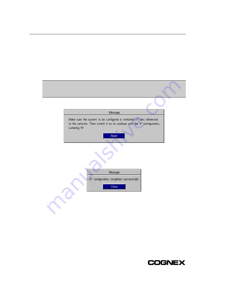
11. Click OK. The message box shown in Figure C-4 appears.
Figure C-4: IP Configuration Message Box
12. Cycle power on the In-Sight 3400 sensor by removing, then applying, power to the sensor’s
24VDC port. The message in Figure C-5 appears when the In-Sight 3400 sensor is located
on the network.
Figure C-5: IP Configuration Successful Message Box
If the message in step 12 does not appear within one minute of cycling power, click Abort. The
Logon dialog will reappear. Verify that the IP Address is valid and the Subnet Mask is appropriate
for the local network. Make corrections as necessary, and retry steps 1 through 12. Contact your
network administrator if problems persist.
64
Содержание In-Sight 3400
Страница 1: ......
Страница 2: ......
Страница 6: ...Precautions iv ...
Страница 12: ...List of Tables x ...
Страница 46: ...In Sight 3400 Installation 34 ...
Страница 88: ...Installing the Remote Head Camera Mount 76 ...
Страница 90: ...Installing the In Sight 3400 Vision Sensor www cognex com P N 597 0025 02 ...


