3.5
Inputs and outputs
Test the inputs
(SE, FE, E1, E2, E3):
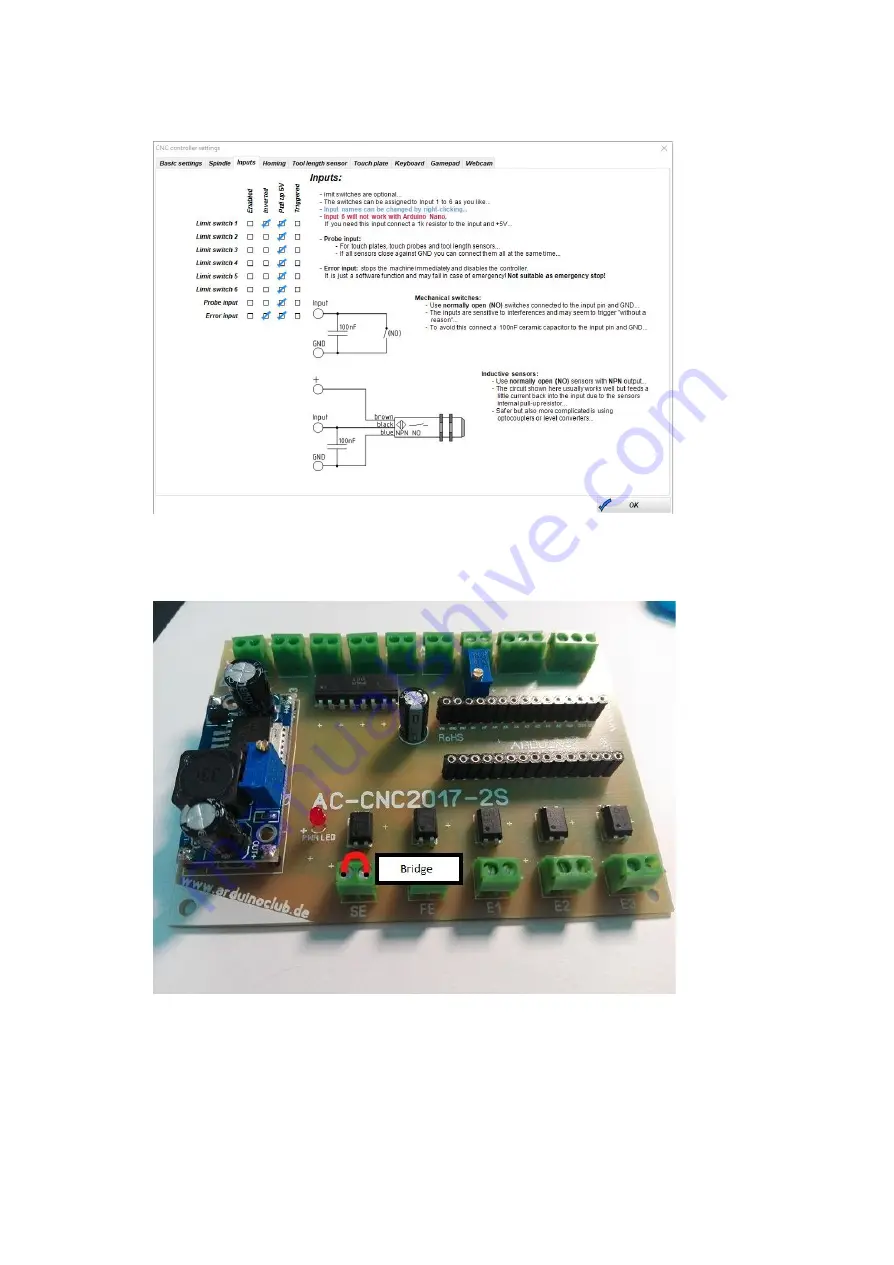
Open Estlcam and got to „Setup->CNC Controller->Inputs“
Figure 3.5.1
At the screw terminals, use the wire to bridge the limit switch 1, 2, 3; Sensor input and
error input (E1, E2, E3, SE, FE).
Figure 3.5.2
If all the inputs are working, this was shown as "triggered".
If problems occur, program the controller new, check all solder, check the installation
direction of the Optocoupler.
Measure if the screw terminals are connected to the + 5V.


