


CMT2380F17
Rev0.1 | 288/347
www.cmostek.com
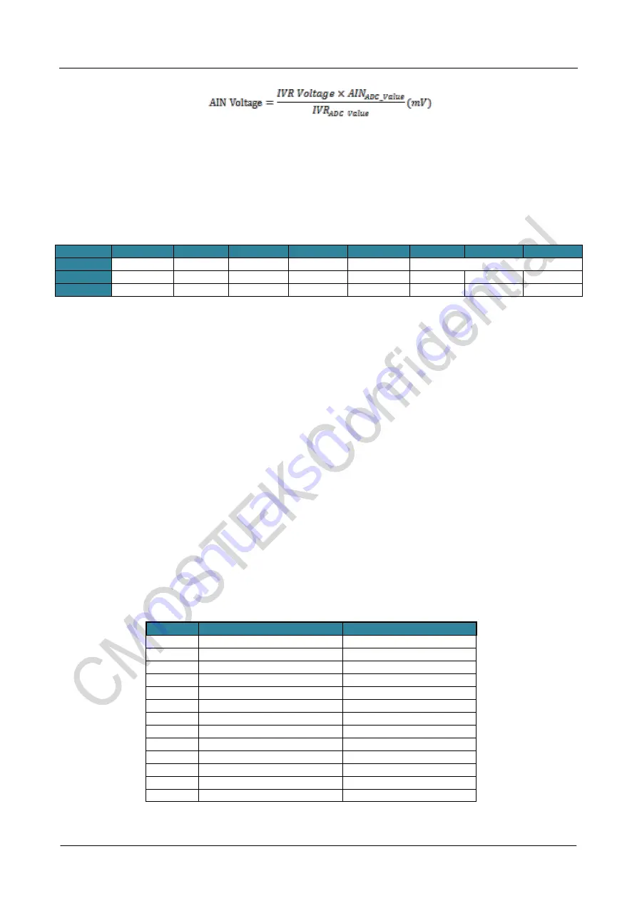
Note: To read the IVR ADC Presorted value please reference 27.3 How to read IVR (1.4V) ADC Prestored
value .
26.3
ADC Register
ADCON0
:
ADC Control Register 0
SFR Page
= 0~F
SFR Address = 0xC4
Bit
7
6
5
4
3
2
1
0
Name
ADCEN
ADCWI
CHS3
ADCI
ADCS
CHS[2:0]
R/W
R/W
R/W
R/W
R/W
R/W
R/W
R/W
R/W
Reset Value
0
0
0
0
0
0
0
0
B Bit 7: ADCEN, ADC Enable.
0: Clear to turn off the ADC block.
1: Set to turn on the ADC block. At least 5us ADC enabled time is required before set ADCS.
Bit 6: ADCWI, ADC Window Compare Interrupt flag.
0: ADC0 Window Comparison Data match has not occurred since this flag was last cleared. The flag
must be cleared by software.
1: This flag is set when ADC Window Comparison Data match has occurred. An interrupt is invoked if it is
enabled. The interrupt on this flag can be enabled by EADCWI. (ADCFG1.6)
Bit 5: CHS3. Combined CH2~0 to select ADC input channel.
Bit 4: ADCI, ADC Interrupt Flag.
0: The flag must be cleared by software.
1: This flag is set when an A/D conversion is completed. An interrupt is invoked if it is enabled. The
interrupt on this flag can be blocked by IGADCI (ADCFG1.7).
Bit 3: ADCS. ADC Start of conversion. 0: ADCS cannot be cleared by software.
1: Setting this bit by software starts an A/D conversion. On completion of the conversion, the ADC
hardware will clear ADCS and set the ADCI. A new conversion may not be started while either ADCS or
ADCI is high.
Bit 2~0: CHS2 ~ CHS1, Input Channel Selection for ADC analog multiplexer.
In Single-ended mode:
ACHS
CHS3~0
Selected Channel
0
0 0 0 0
AIN0 (P1.0)
0
0 0 0 1
AIN1 (P1.1)
0
0 0 1 0
AIN2 (P2.2)
0
0 0 1 1
AIN3 (P2.4)
0
0 1 0 0
AIN4 (P3.0)
0
0 1 0 1
AIN5 (P1.5)
0
0 1 1 0
AIN6 (P1.6)
0
0 1 1 1
AIN7 (P1.7)
1
0 0 0 0
Int. VREF (IVR/1.4V)
1
0 0 0 1
AVSS
1
0 0 1 0
Reserved
1
0 0 1 1
Reserved
Others
Reserved
Содержание CMT2380F17
Страница 27: ...CMT2380F17 Rev0 1 27 347 www cmostek com 1 25 Phase Noise...
Страница 111: ...CMT2380F17 Rev0 1 111 347 www cmostek com INT2IS 1 0 Selected Port Pin of nINT2 00 P4 4 01 P3 0 10 P1 1 11 P1 6...
Страница 131: ...CMT2380F17 Rev0 1 131 347 www cmostek com Figure 16 1 Timer 0 Mode 0 Structure Figure15 2 Timer 1 Mode 0 Structure...
Страница 161: ...CMT2380F17 Rev0 1 161 347 www cmostek com Figure 16 32 Split Timer 3 Mode 1 Structure AR with Ex INT...
Страница 177: ...CMT2380F17 Rev0 1 177 347 www cmostek com Figure 17 3 PCA Interrupt System...
Страница 239: ...CMT2380F17 Rev0 1 239 347 www cmostek com Figure 19 5 8 bit Timer Mode Configuration for S1BRG S1TME 1...
Страница 246: ...CMT2380F17 Rev0 1 246 347 www cmostek com SnMIPS S0MI S1MI 1 P3 3 P4 7...
Страница 289: ...CMT2380F17 Rev0 1 289 347 www cmostek com...