Installation – Local network
24
P2260JH | 2019-05
Apex Tool Group
6
EN
6.2
Setting up controller
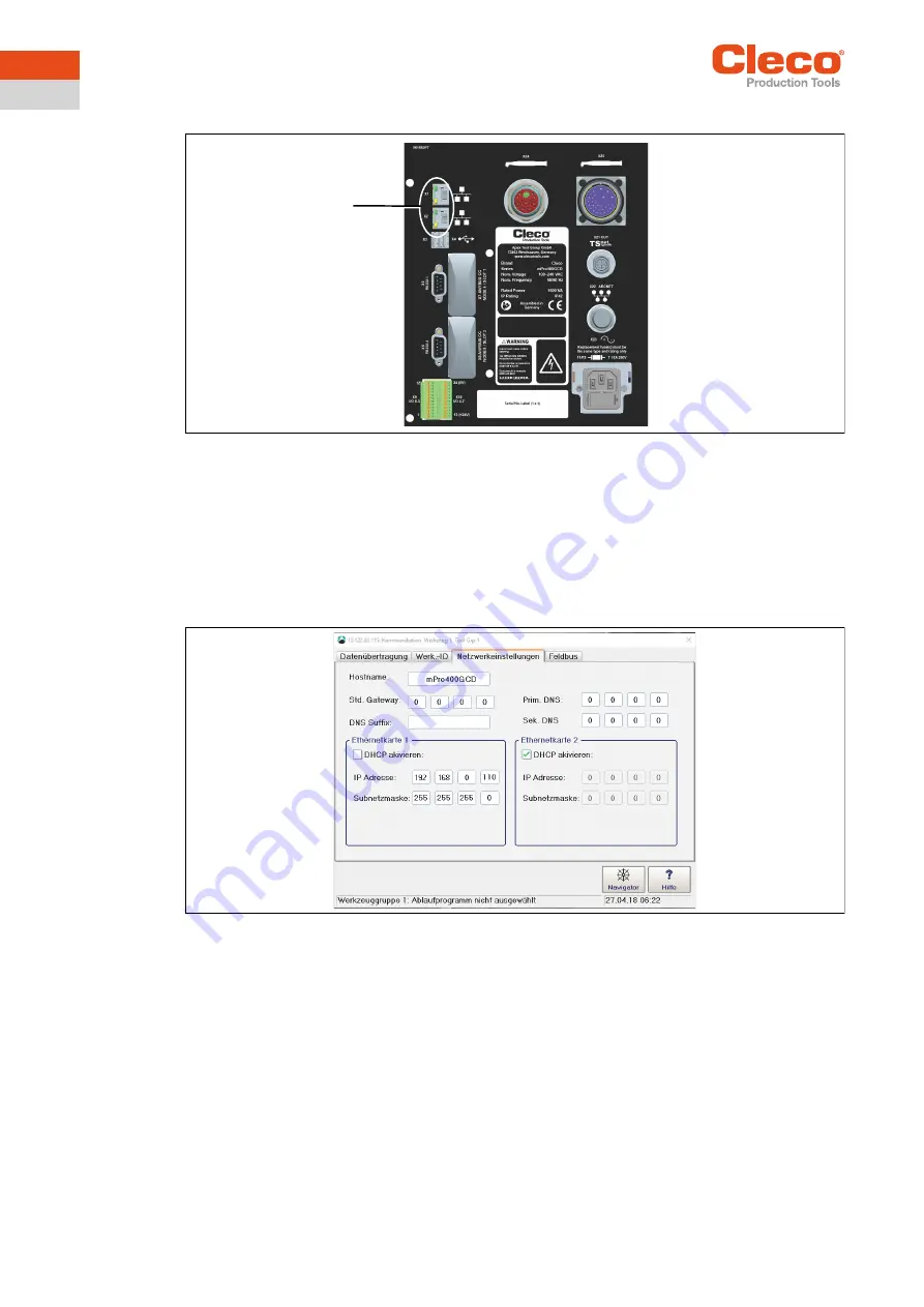
Fig. 6-1: Connections illustrated on the mPro400GCD-P underside
Connect the network cable to X1 (or X2) Ethernet port and connect the access point to the controller.
Switch on the access point.
6.2.1
Configuring network settings
Enter IP address for controller (example here at ethernet port 1)
1. Select
Navigator > Communication > Network settings
.
Fig. 6-2: Network settings (existing network)
2.
Enable DHCP
: Remove tick.
3. Enter the
IP address and subnet mask
for the controller.
→ Each IP address must only be assigned once.
→ The IP addresses for the access point, controller, tool ands service PC must be in the same subnet.
4. Enter the
Std. gateway
if a gateway is used.
5. Select <Navigator> and save the settings with <Accept>.
6. The
Navigator Menu
is displayed.
7. Restart the controller.
6.2.2
Configuring tool RF settings
1. Connect the tool holder to the serial port XS4 (or XS5) with the infrared interface.
2. Switch the tool on and place it in the tool holder.
3. Select
Navigator > Utilities > System settings > LiveWirelCellCore RF configuration
.
X1
X2


