Menus and Functions
10
P2398PM | 2018-12
Apex Tool Group GmbH
3
EN
3.2
LCD setup
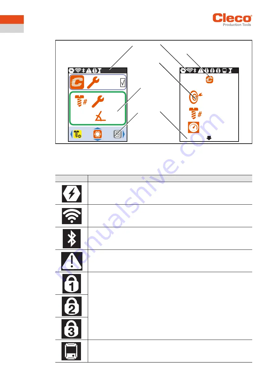
Abb. 3-1: Setup of the menus using the run screen and a submenu as an example
3.2.1
Header
The symbols in the header indicate which functions are activated.
τ
15 Nm
τ
15.7 Nm
270°
3/10
270
3
350
1
Footer
Run screen
Submenus and
parameters
Header
Symbol for the current menu
Symbol
Description
Battery is plugged in.
WLAN connection is available.
Bluetooth connection is available.
Displayed in the
Diagnostics
menu and with warnings.
PIN is required.
The number on the lock indicates the active access level.
mPro mode is activated.


