


7- 1
7. External Input/Output
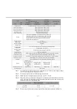
7-1 Interface
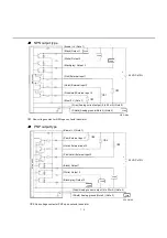
7-1-1 Input/Output Circuit
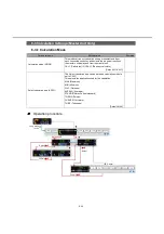
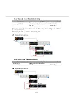
SA-SD1AP, SA-SD1AP-P
Color
Signal
I/O
Remarks
Brown
+V
−
24 VDC
Black
Output 1
OUT
Refer to "6-2-4 External Output."
White
Output 2
OUT
Black/gray
Output 3
OUT
Pink
External input 1
IN
Refer to "6-2-3 External Input."
Violet
External input 2
IN
Pink/violet
External input 3
IN
Blue
0 V
−
Ground for power supply
Gray
Analog output
OUT
Current output (4 to 20 mA)
Shield
Analog ground
−
Note 1: Use shielded wires for analog outputs.
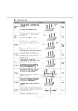
SA-SD1AC, SA-SD1AC-P
Color
Signal
I/O
Remarks
Black
Output 1
OUT
Refer to "6-2-4 External Output."
White
Output 2
OUT
Black/gray
Output 3
OUT
Pink
External input 1
IN
Refer to "6-2-3 External Input."
Violet
External input 2
IN
Pink/violet
External input 3
IN
Gray
Analog output
OUT
Current output (4 to 20 mA)
Shield
Analog ground
−
Note 1: Use shielded wires for analog outputs.
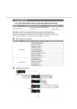
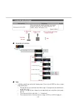
SA-SD1C, SA-SD1C-P
Color
Signal
I/O
Remarks
Black
Output 1
OUT
Refer to "6-2-4 External Output."
White
Output 2
OUT
Black/gray
Output 3
OUT
Pink
External input 1
IN
Refer to "6-2-3 External Input."
Violet
External input 2
IN
Pink/violet
External input 3
IN
Note 1: Power is supplied through master unit connectors.
■
■
■