background image

5-7

Cisco XR 12416 and Cisco XR 12816 Router Chassis Installation Guide

OL-17440-01

Chapter 5      Maintaining the Router

Cleaning or Replacing the Chassis Air Filter

Step 4

Reinstall the hardware to the opposite sides of the front door:

a.

Mount pivot blocks to the left side and tighten the screws until snug.

b.

Mount the bumpers to the right side and tighten the screws until snug.

Step 5

Attach the front door to the chassis:

a.

Remove the hinge pins from the hinges on the right side of the chassis.

b.

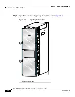
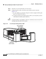
Align the pivot blocks on the front door with the hinges on the right side of 
the chassis and install the hinge pins to hold the door in place (see 

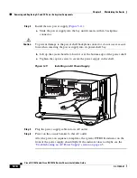
Figure 5-2

).

c.

Close the front door by pressing the latch button, allowing the door latch to 
engage with the hinge pins on the chassis.

Step 6

Repeat 

Step 1

 through 

Step 5

 for the bottom door.

Cleaning or Replacing the Chassis Air Filter

The router is equipped a user-serviceable air filter that removes dust drawn into 
the router. One time per month (or more often in dusty environments), examine 
the air filter for damage and cleanliness.

Caution

Damage to the air filter can restrict the airflow, cause overheating in the router, 
and degrade EMI performance. Be careful when cleaning and replacing the filter.

Содержание XR 12416

Страница 1: ... Off the Router page 5 2 Removing and Installing Front Doors page 5 3 Cleaning or Replacing the Chassis Air Filter page 5 7 Removing and Replacing Blower Modules page 5 10 Removing and Replacing AC and DC Power Subsystem Components page 5 14 Removing and Replacing the Standard AC Input Power Shelf page 5 19 Removing and Replacing the Optional 2 Level AC Input Power Shelf page 5 24 Upgrading to the...

Страница 2: ...ped with the router Powering Off the Router Most field replaceable units FRUs can be removed and replaced with the power on and the system operating This is known as online insertion and removal OIR Power supplies line cards the RP CSCs SFCs and alarm cards all support OIR Unless otherwise noted the maintenance tasks described in this chapter can be performed while the router remains powered on In...

Страница 3: ...the door hinges mounted on the left side of the chassis so that they open from right to left This section describes how to change the front doors to open from left to right by installing the hinges on the opposite side Use the following procedure to change the location of the hinges Note The illustrations in this procedure show the top front door but the procedure is the same for either the top or...

Страница 4: ...RX TX 2 RX TX 3 RX TX 4 RX TX 5 RX TX 6 RX TX 7 RX TX 8 RX TX 9 RX TX 10 RX TX 11 RX AC TIV E CA RR IER RX PK T OC 48 STM 16 SCPOS AC TIV E 0 CA RR IER RX CE LL OC 12 STM 4 ATM FAST ETERNET SL OT 0 ROUTE PROCESSOR SL OT 1 CO LL LIN K TX RX RJ 45 MII RE SE T AU X CO NS OL E EJE CT SL OT 0 ROUTE PROCESSOR SL OT 1 CO LL LIN K TX RX RJ 45 MII RE SE T AU X CO NS OL E EJE CT FAST ETERNET AC TIV E 0 CA R...

Страница 5: ...OK FAULT TEMP I LIM PWR OK FAULT TEMP I LIM ALARM EN AB LE D FA IL AC O LT ALARM CS C 0 FA IL 1 0 1 2 EN AB LE D CR IT IC AL MA JO R MI NO R SF C AC TI VE 0 CA RR IE R RX PK T AC TI VE 1 CA RR IE R RX PK T AC TI VE 2 CA RR IE R RX PK T AC TI VE 3 CA RR IE R RX PK T Q OC 3 STM POS 6DS3 SMB P H F DOWN LOOP RA LA CDHNT CD TX 0 RX TX 1 RX TX 2 RX TX 3 RX TX 4 RX TX 5 RX 12DS3 SMB P H F DOWN LOOP RA LA...

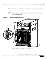
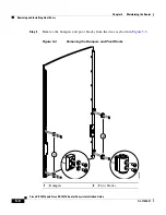
Страница 6: ...ront Doors 5 6 Cisco XR 12416 and Cisco XR 12816 Router Chassis Installation Guide OL 17440 01 Step 3 Remove the bumpers and pivot blocks from the door as shown in Figure 5 3 Figure 5 3 Removing the Bumpers and Pivot Blocks 1 Bumpers 2 Pivot blocks 149540 2 1 ...

Страница 7: ...n the front door with the hinges on the right side of the chassis and install the hinge pins to hold the door in place see Figure 5 2 c Close the front door by pressing the latch button allowing the door latch to engage with the hinge pins on the chassis Step 6 Repeat Step 1 through Step 5 for the bottom door Cleaning or Replacing the Chassis Air Filter The router is equipped a user serviceable ai...

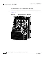
Страница 8: ...ollowing procedure to clean or replace the air filter Step 1 Loosen the 4 captive screws on the air filter door and pivot the door open Figure 5 4 Figure 5 4 Opening the Chassis Air Filter Door ALARM C S C 0 FA IL 1 0 1 2 E N A B LE D S FC Q OC 3 STM POS 6DS3 SMB P H F 12DS3 SMB P H F R X T X 1 1 R X OC 48 STM 16 SCPOS OC 12 STM 4 ATM FAST ETERNET ROUTE PROCESSOR 138149 ...

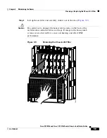
Страница 9: ... 5 Caution Be careful not to damage the honeycomb screens on the back of the air filter door and in the fabric card cage Damage to the honeycomb screens can restrict airflow cause overheating and affect EMI performance Figure 5 5 Removing the Chassis Air Filter ALARM C S C 0 FA IL 1 0 1 2 E N A B LE D S FC Q OC 3 STM POS 6DS3 SMB P H F 12DS3 SMB P H F R X T X 1 1 R X OC 48 STM 16 SCPOS OC 12 STM 4...

Страница 10: ...eaned air filter into the air filter door Step 5 Close the air filter door and tighten the 4 captive screws Caution Align and seat the door carefully to avoid damaging the EMI preventive gasket contacts on the door The air filter door must be closed and secured at all times to maintain correct EMI performance Removing and Replacing Blower Modules The blower modules support online insertion and rem...

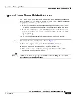
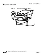
Страница 11: ...up orientation with the three fan air intake openings face down Heads down orientation Install the blower module in the lower blower module bay in the heads down orientation with the three fan air intake openings face up Use the following procedure to remove and replace the blower modules Step 1 Remove the blower module from the chassis Figure 5 6 a Loosen the captive screw on each side of the blo...

Страница 12: ...ing and Replacing Blower Modules 5 12 Cisco XR 12416 and Cisco XR 12816 Router Chassis Installation Guide OL 17440 01 Figure 5 6 Removing the Upper Blower Module PWR OK FAULT TEMP I LIM PWR OK FAULT TEMP I LIM PWR OK FAULT TEMP I LIM 26213 ...

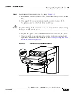
Страница 13: ...tes with the backplane connector at the back of the module bay Caution To prevent damage to the connectors do not use excessive force when inserting the blower module into the chassis c Tighten the captive screws on the blower module to secure it to the chassis The green OK status indicator on the front of the blower module should light If the OK indicator does not light see the Isolating Cooling ...

Страница 14: ...on and ensures session preservation However to maintain operational redundancy proper cooling and meet EMI compliance standards you must have all three standard or four optional working power supplies installed When you remove a failed power supply with the router in operation perform the replacement as quickly as possible Make sure you have the tools and the replacement power supply ready before ...

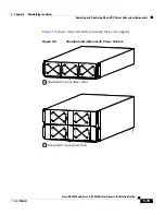
Страница 15: ...stem Components Figure 5 8 shows AC power shelves housing the power supplies Figure 5 8 Standard and Optional AC Power Shelves 27836 PWR OK FAULT TEMP I LIM PWR OK FAULT TEMP I LIM PWR OK FAULT TEMP I LIM PWR OK FAULT TEMP I LIM PWR OK FAULT TEMP I LIM PWR OK FAULT TEMP I LIM PWR OK FAULT TEMP I LIM Standard AC input power shelf Optional AC input power shelf a b ...

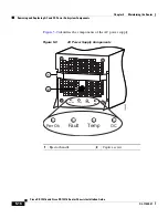
Страница 16: ...m Components 5 16 Cisco XR 12416 and Cisco XR 12816 Router Chassis Installation Guide OL 17440 01 Figure 5 9 identifies the components of the AC power supply Figure 5 9 AC Power Supply Components 1 Ejector handle 2 Captive screw 129495 Pwr Ok Fault Temp OC 1 2 Pwr Ok Fault Temp OC ...

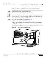
Страница 17: ...ned to that AC outlet Warning To ensure that power remains off while you are performing this procedure tape the circuit breaker switch in the off 0 position Step 3 Remove the PEM from the power shelf Figure 5 10 a Loosen the captive screw to release the ejector handle b Pivot the ejector handle down to eject the power supply from its backplane connector c Slide the power supply out of its bay whil...

Страница 18: ... the power supply into its power shelf bay b Lift up the ejector handle to hook it over the bottom edge of the power shelf c Tighten the captive screw to secure the power supply in the shelf Figure 5 11 Installing an AC Power Supply Step 5 Plug the power supply cable into its AC outlet Step 6 Power on the circuit breaker to that AC outlet After the power on sequence completes the green PWR OK indi...

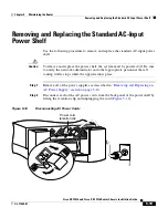
Страница 19: ...nd replace the power shelf the system must be powered off Be sure to notify the network administrator and other appropriate personnel that all routing traffic stops while the upgrade takes place Step 1 Remove all of the power supplies as described in Removing and Replacing an AC Power Supply section on page 5 14 Step 2 Disconnect each of the AC power cords from the back panel of the power shelf by...

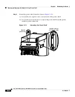
Страница 20: ...5 13 a Loosen the two captive screws on each side of the power shelf b Loosen the ejector jackscrew to unseat the power shelf from the power interface panel connectors Figure 5 13 Unseating the Power Shelf AC TIV E 0 CA RR IER RX PK T 1 DOWN LOOP RA LA CDHNT CD TX 0 RX TX 1 RX TX 2 RX TX DOWN LOOP RA LA CDHNT CD TX 0 RX TX 1 RX TX 2 RX TX SL OT 0 SL OT 1 RE SE T AU X EJ EC T 28020 Captive screws 2...

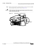
Страница 21: ...h side and slowly pulling the shelf along the chassis track to remove it Figure 5 14 Warning The AC input power shelf weighs approximately 21 pounds 9 5 kg Use two hands to remove the power shelf Figure 5 14 Removing the AC Input Power Shelf AC TIV E 0 CA RR IER RX PK T 1 DOWN LOOP RA LA CDHNT CD TX 0 RX TX 1 RX TX 2 RX TX DOWN LOOP RA LA CDHNT CD TX 0 RX TX 1 RX TX 2 RX TX SL OT 0 SL OT 1 RE SE T...

Страница 22: ...Figure 5 15 a Be sure the holes on each side of the power shelf are aligned with the guide pins on each side of the chassis b Carefully slide the power shelf into place until its two connectors just mate with the power interface panel connectors Caution To prevent damage to the interface connectors do not use excessive force when inserting the power shelf into the chassis Figure 5 15 Connecting th...

Страница 23: ...eat the power shelf to the chassis Figure 5 16 a Tighten the ejector jackscrew b Tighten the captive screws on each flange Figure 5 16 Seating the Power Shelf AC TIV E 0 CA RR IER RX PK T 1 DOWN LOOP RA LA CDHNT CD TX 0 RX TX 1 RX TX 2 RX TX DOWN LOOP RA LA CDHNT CD TX 0 RX TX 1 RX TX 2 RX TX SL OT 0 SL OT 1 RE SE T AU X EJ EC T 28020 Captive screws 2 on each side Ejector jackscrew ...

Страница 24: ... 17 Reconnecting AC Power Cords Step 9 Reinstall the power supplies as described in Removing and Replacing an AC Power Supply section on page 5 14 Removing and Replacing the Optional 2 Level AC Input Power Shelf Use the following procedure to remove and replace the optional 2 level AC input power shelf Caution To remove and replace the power shelf the system must be powered off Notify the network ...

Страница 25: ...vel AC Input Power Shelf Step 1 Remove all of the power supplies as described in Removing and Replacing an AC Power Supply page 5 14 Step 2 Disconnect each of the AC power cords from the back panel of the power shelf by lifting the retention clip and unplugging the cord Figure 5 18 Figure 5 18 Disconnecting the AC Power Cords 129493 Power cord retention clip ...

Страница 26: ...on the chassis power interface panel Step 5 Remove the power shelf by grasping the flanges on each side and slowly pulling the shelf along the chassis track to remove it Figure 5 19 Warning The AC input power shelf weighs approximately 42 pounds 19 05 kg Use two hands to remove the power shelf Figure 5 19 Removing the AC Input Power Shelf AC TIV E 0 CA RR IER RX PK T 1 DOWN LOOP RA LA CDHNT CD TX ...

Страница 27: ...ors Figure 5 20 a Be sure the holes on each side of the power shelf are aligned with the guide pins on each side of the chassis b Carefully slide the power shelf into place until its two connectors just mate with the power interface panel connectors Caution To prevent damage to the interface connectors do not use excessive force when inserting the power shelf into the chassis Figure 5 20 Connectin...

Страница 28: ...ng the flanges on each side and slowly sliding the shelf into the chassis along the track Figure 5 21 a Tighten the ejector jackscrew b Tighten the two captive screws on each flange Figure 5 21 Installing the AC Input Power Shelf AC TIV E 0 CA RR IER RX PK T 1 DOWN LOOP RA LA CDHNT CD TX 0 RX TX 1 RX TX 2 RX TX DOWN LOOP RA LA CDHNT CD TX 0 RX TX 1 RX TX 2 RX TX SL OT 0 SL OT 1 RE SE T AU X EJ EC ...

Страница 29: ...ut Power Shelf Step 9 Reconnect each of the AC power cords to the back panel of the power shelf and secure them in place with their retention clips Figure 5 22 Figure 5 22 Reconnecting AC Power Cords Step 10 Reinstall the power supplies as described in Removing and Replacing an AC Power Supply section on page 5 14 beginning with Step 6 33452 Power cord retention clip ...

Страница 30: ... one level power shelf following the procedures in Removing and Replacing the Standard AC Input Power Shelf section on page 5 19 through Step 4 Step 2 Install the optional 2 level power shelf following the procedures in Removing and Replacing the Optional 2 Level AC Input Power Shelf section on page 5 24 beginning with Step 6 Step 3 Replace the old cover with the new cover you received in the upgr...

Страница 31: ... Chapter 5 Maintaining the Router Removing and Replacing a DC PEM Removing and Replacing a DC PEM This section contains the procedure to remove and replace an DC PEM from the chassis Before you begin this procedure read the Removing and Replacing an AC Power Supply section on page 5 14 ...

Страница 32: ...o XR 12416 and Cisco XR 12816 Router Chassis Installation Guide OL 17440 01 Figure 5 23 identifies the components of a DC power supply Figure 5 23 DC Power Supply Components 1 Handle 3 Ejector lever 2 Fan 4 Power switch 129494 PWR OK FAULT TEMP OC PWR OK FAULT TEMP OC 3 1 2 4 ...

Страница 33: ...hat PEM Warning To ensure that power remains off while you are performing this procedure tape the circuit breaker switch in the off 0 position Step 3 Loosen the captive screw on the ejector handle and pivot the lever down to eject the PEM from its bay Figure 5 24 Step 4 Remove the PEM from the power shelf Figure 5 24 a Pull the PEM halfway out of its bay b Slide the PEM out of its bay while suppor...

Страница 34: ... 5 34 Cisco XR 12416 and Cisco XR 12816 Router Chassis Installation Guide OL 17440 01 Figure 5 24 Removing a DC PEM PWR OK FAULT TEMP PWR OK FAULT TEMP PWR OK FAULT TEMP PWR OK FAULT TEMP 26212 Loosen captive screw a Pivot ejector lever b Pull module out of shelf c ...

Страница 35: ...and lift the ejector lever into place to seat the PEM to the backplane connector Caution To prevent damage to the power shelf backplane connector do not use excessive force when inserting the PEM into its power shelf bay d Tighten the captive screw to secure the PEM in the power shelf Note Because the PEM is powered redundantly by other PEMs in its power load zone the fault indicator may go on Thi...

Страница 36: ... by switching on its circuit breaker After the power on sequence completes the green PWR OK indicator on the front of the PEM should light If the indicator does not light see the Troubleshooting a DC Power Supply section on page 4 10 PWR OK FAULT TEMP PWR OK FAULT TEMP PWR OK FAULT TEMP PWR OK FAULT TEMP 27214 Loosen captive screw and pivot ejector lever a Close ejector lever to seat power module ...

Страница 37: ...he system must be powered off Notify the network administrator and other appropriate personnel that all routing traffic stops while the upgrade takes place Step 1 Remove all of the DC PEMs as described in the Removing and Replacing a DC PEM procedure on page 5 31 through Step 4 Step 2 Remove the power cable cover by loosening its retaining screw Figure 5 26 Figure 5 26 Removing the Source DC Power...

Страница 38: ...d for source DC wiring you must be sure which power cables are connected to the proper positive and negative terminal studs Typically green or green and yellow indicate a ground cable while power cable leads may be labeled positive or negative Because this is not always the case the safest way to indicate the polarity of a cable is to note its color and identify it as described in this procedure W...

Страница 39: ...assis Installation Guide OL 17440 01 Chapter 5 Maintaining the Router Removing and Replacing the DC Power Shelf Figure 5 27 Disconnecting the Source DC Power Cables 28018 Ground A1 A1 A2 A2 B2 B2 B1 B1 Ground B1 Negative cable lug Positive cable lug ...

Страница 40: ...oosen the ejector jackscrew to unseat the power shelf from the connectors on the chassis power interface panel Warning The DC input power shelf weighs approximately 10 2 pounds 4 6 kg Use two hands to remove the power shelf Figure 5 28 Unseating the Power Shelf AC TIV E 0 CA RR IER RX PK T 1 DOWN LOOP RA LA CDHNT CD TX 0 RX TX 1 RX TX 2 RX TX DOWN LOOP RA LA CDHNT CD TX 0 RX TX 1 RX TX 2 RX TX SL ...

Страница 41: ...e the power shelf by grasping the flanges on each side and slowly pulling the shelf along the chassis track to remove it Figure 5 29 Figure 5 29 Removing the DC Input Power Shelf AC TIV E 0 CA RR IER RX PK T 1 DOWN LOOP RA LA CDHNT CD TX 0 RX TX 1 RX TX 2 RX TX DOWN LOOP RA LA CDHNT CD TX 0 RX TX 1 RX TX 2 RX TX SL OT 0 SL OT 1 RE SE T AU X EJ EC T 27967 Track on chassis ...

Страница 42: ...5 30 a Be sure the holes on each side of the power shelf are aligned with the guide pins on each side of the chassis b Carefully slide the power shelf into place until its two connectors just mate with the power interface panel connectors Caution To prevent damage to the interface connectors do not use excessive force when inserting the power shelf into the chassis Figure 5 30 Connecting the DC In...

Страница 43: ...10 2 pounds 4 6 kg Use two hands to remove the power shelf Figure 5 31 Seating the DC Input Power Shelf Step 10 Reconnect the ground and each pair of power cables to the DC input terminal studs as follows Figure 5 32 Caution Be sure to connect the cables according to the color coding notes and labels you made in Step 4 AC TIV E 0 CA RR IER RX PK T 1 DOWN LOOP RA LA CDHNT CD TX 0 RX TX 1 RX TX 2 RX...

Страница 44: ...irst a Reconnect the ground cable to the ground terminal studs Beginning with terminal studs B2 b Reconnect the positive cable to the positive terminal studs For example B2 c Reconnect the negative cable to the negative terminal studs For example B2 Repeat steps b and c for the remaining pairs of terminal studs Figure 5 32 Reconnecting the Source DC Power Cables to the Power Shelf 26866 Ground cab...

Страница 45: ...to 60 VDC Caution If any of the voltage readings are not within the specified range do not proceed Check for correct polarity and DC source voltage Step 13 Reinstall the power cable cover Figure 5 33 Figure 5 33 Reinstalling the Source DC Power Cable Cover Step 14 Power off the source DC circuit breakers for the PEMs Step 15 Install all of the DC PEMs as described in the Removing and Replacing a D...

Страница 46: ...s for removing and installing a router processor RP card or a line card from the upper or lower card cage The upper and lower card cages have 9 slots and the lower card cage is a reverse image of the top card cage Alarm cards can only be installed in their specific slots which are labeled as Alarm Card Caution Handle all cards by the metal card carrier edges only avoid touching the board or any co...

Страница 47: ... card to unseat card Grasp card carrier to slide card out of slot c b Loosen captive screws a A C TI V E 0 C A R R IE R R X P K T A C TI V E 1 C A R R IE R R X P K T A C TI V E 2 C A R R IE R R X P K T A C TI V E 3 C A R R IE R R X P K T Q OC 3 STM POS Pivot ejector levers away from card to unseat card Grasp card carrier to slide card out of slot c b Loosen captive screws a 6DS3 SMB P H F DOWN LOO...

Страница 48: ...ter is equipped with two alarm cards One card occupies the dedicated far left slot of the upper card cage the second occupies the dedicated far right slot of the lower card cage see Figure 5 35 The alarm card slot differs from the rest of the card cage slots it is physically narrower has a different backplane connector and is labeled as an Alarm Card slot Alarm cards can only be installed in these...

Страница 49: ... R RX PK T OC 48 STM 16 SCPOS AC TI VE 0 C AR R IE R R X C EL L OC 12 STM 4 ATM FAST ETERNET SL OT 0 ROUTE PROCESSOR SL OT 1 CO LL LI NK TX RX RJ 4 5 M II RE SE T AU X CO NS O LE EJ EC T SL OT 0 ROUTE PROCESSOR SL OT 1 CO LL LI NK TX RX RJ 4 5 M II RE SE T AU X CO NS O LE EJ EC T FAST ETERNET AC TI VE 0 C AR R IE R R X C EL L OC 12 STM 4 ATM AC TI VE CA RR IE R RX PK T OC 48 STM 16 SCPOS 12DS3 SMB...

Страница 50: ... Figure 5 36 Removing an Alarm Card from the Upper Card Cage Step 3 Replace the card by reversing the procedures in Steps 1 and 2 28347 AC TI VE 0 C AR R IE R R X PK T AC TI VE 1 C AR R IE R R X PK T AC TI VE 2 C AR R IE R R X PK T AC TI VE 3 C AR R IE R R X PK T Q OC 3 STM POS 6DS3 SMB P H F DOWN LOOP RA LA CDHNT CD TX 0 RX TX 1 RX TX 2 RX TX 3 RX TX 4 RX TX 5 RX 12DS3 SMB P H F DOWN LOOP RA LA C...

Страница 51: ... for the CSCs and SFCs CSCs are installed in the left two card slots labeled CSC 0 and 1 SFCs are installed in the right three card slots labeled SFC 0 1 and 2 Use the following procedure to remove and replace switch fabric cards Step 1 Loosen the 4 captive screws on the air filter door and pivot the door open Figure 5 37 Figure 5 37 Opening the Chassis Air Filter Door ALARM C S C 0 FA IL 1 0 1 2 ...

Страница 52: ...card from the backplane connector b Grasp the card by its metal card carrier and slide the card out of the slot Figure 5 38 Place the card directly into an antistatic bag or other ESD preventive container Figure 5 38 Removing a Card from the Switch Fabric Card Cage Step 3 To install the card reverse the procedure in Step 2 Step 4 Close the air filter door and tighten the captive screws 26862 Switc...

Страница 53: ... the defective chassis A spare scissor jack platform with the anchor clips and bolts that came with the original chassis is available to remove the defective chassis from the equipment rack Components are transferred from the defective chassis directly to the replacement chassis The replacement chassis is installed in the equipment rack after all components are installed This approach has the adva...

Страница 54: ... Removal Use the following procedure to prepare the installed chassis for removal Step 1 Power off the router see Powering Off the Router page 5 2 Step 2 Power off the circuit breakers to the power supplies Step 3 Disconnect the power cords from the power shelf For a standard AC power shelf see Step 2 of Removing and Replacing the Standard AC Input Power Shelf page 5 19 For an optional AC power sh...

Страница 55: ...om the line card d Carefully remove the cables from the cable tray and carefully place the cable bundle out of the way e Repeat steps a through d for each line card Step 8 Remove the vertical cable management troughs see Attaching the Vertical Cable Management Trough page 3 23 Removing and Installing System Components Use the following procedure to remove and install system components from one cha...

Страница 56: ... rack Step 1 Remove all grounding connections to the chassis See NEBS Supplemental Unit Bonding and Grounding Guidelines section on page 2 21 Step 2 Position the scissor jack platform from the original router shipping package in front of the rack mounting platform in the rack Figure 5 39 Step 3 Turn the scissor jack screw counterclockwise to slowly raise the top of the scissor jack platform to the...

Страница 57: ... the top of the chassis down remove the screws that secure the chassis to the mounting flanges on the rack Figure 5 40 Set the screws aside for use to install the replacement chassis Warning The chassis is still supported by the rack mounting platform installed in the bottom of the rack but should be held to prevent the possibility of tipping out of the front of the rack ...

Страница 58: ...o XR 12416 and Cisco XR 12816 Router Chassis Installation Guide OL 17440 01 Figure 5 40 Removing the Mounting Screws 26864 Chassis mounting holes group E Chassis mounting holes group D Chassis mounting holes group C Chassis mounting holes group B Chassis mounting holes group A ...

Страница 59: ...f the rack mounting table and onto the scissor jack platform Step 6 Install the four chassis anchor clips through the slots in the bottom of the chassis Warning One person should be holding the side of the chassis to prevent it from tipping a Align the holes with the bolt holes in the platform b Insert and tighten the four bolts to prevent the chassis from shifting on the scissor jack platform Fig...

Страница 60: ...s can be repackaged for shipping Use the packaging and unpacking instructions that came with the replacement chassis to repack and ship a defective chassis to the factory SL OT 0 SL OT 1 RE SE T AU X CO NS OL E EJ EC T AC TI VE 0 CA RR IE R RX CE LL AC TI VE CA RR IE R RX PK T DOWN LOOP RA LA CDHNT CD TX 0 RX TX 1 RX TX 2 RX TX 3 RX TX 4 RX TX 5 RX TX 6 RX DOWN LOOP RA LA CDHNT CD TX 0 RX TX 1 RX ...

Страница 61: ...g the Vertical Cable Management Trough page 3 23 Step 5 Connect all line card interface cables using the notes and labeling you created when disconnecting them from the defective chassis Step 6 Connect power cables to the router see Connecting Power to the Power Shelf page 3 34 Step 7 Power on the router Removing and Replacing a Power Bus Board Fuse There are two user replaceable fuses on the powe...

Страница 62: ...Step 2 Remove the power bus board MBus access cover by loosening the four captive screws Figure 5 43 Figure 5 43 MBus Controller Access Cover Step 3 Remove the fuse from the fuse holder using a non conducting fuse extraction tool Figure 5 44 Step 4 Insert the replacement fuse using the fuse extraction tool to hold the replacement fuse align the fuse with the opening in the fuse holder Step 5 Reins...

Страница 63: ...uter to a Cisco XR 12000 Series Router A Cisco 12416 series router can be upgraded to a Cisco XR 12416 router by updating the line cards and software images For information on this process including supported line cards and software upgrade procedures please refer to the Cisco document Upgrading a Cisco 12000 Series Router from Cisco IOS Software to Cisco IOS XR Software F2 F1 MBus F2 5 1V bias Fu...

Страница 64: ...Chapter 5 Maintaining the Router Upgrading a Cisco 12000 Series Router to a Cisco XR 12000 Series Router 5 64 Cisco XR 12416 and Cisco XR 12816 Router Chassis Installation Guide OL 17440 01 ...

Отзывы: