Chapter 5 Maintaining the Router
Removing and Installing a Chassis
5-54
Cisco XR 12416 and Cisco XR 12816 Router Chassis Installation Guide
OL-17440-01
Preparing the Replacement Chassis
Before you can begin to install components in the replacement chassis, you need
to temporarily connect the central office grounding system or interior equipment
grounding system. You can make this connection when the replacement chassis
and scissor-jack platform has been placed near the rack site.
See
“NEBS Supplemental Unit Bonding and Grounding Guidelines” section on
page 2-21
for information about making these connections.
Preparing the Installed Chassis for Removal
Use the following procedure to prepare the installed chassis for removal.
Step 1
Power off the router (see
Powering Off the Router, page 5-2
).
Step 2
Power off the circuit breakers to the power supplies.
Step 3
Disconnect the power cords from the power shelf:
•
For a standard AC power shelf, see Step 2 of
Removing and Replacing the
Standard AC-Input Power Shelf, page 5-19
.
•
For an optional AC power shelf, see Step 2 of
Removing and Replacing the
Optional 2-Level AC-Input Power Shelf, page 5-24
.
•
For a DC power shelf, see Steps 2, 3, and 4 of
Removing and Replacing the
DC Power Shelf, page 5-37
.
Step 4
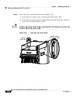
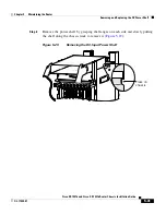
Remove the front doors (see
Removing and Installing Front Doors, page 5-3
).
Step 5
Disconnect RP cables connected to the console port, auxiliary port, or either of
the Ethernet ports, RJ-45 or MII.
Label each of the RP cables before you disconnect the cables.

