Chapter 5 Maintaining the Router
Removing and Replacing the DC Power Shelf
5-38
Cisco XR 12416 and Cisco XR 12816 Router Chassis Installation Guide
OL-17440-01
Step 3
Measure the voltage across each pair of positive (+) and negative (–) terminals of
the power shelf to be sure they are not receiving power.
•
All readings should be 0 VDC.
Warning
Do not proceed if all readings are not 0 (zero) volts. Make sure that the router is
powered off and that all source DC circuit breakers are switched off. Repeat
Step 3
before continuing.
Step 4
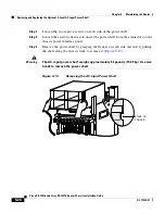
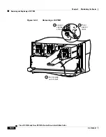
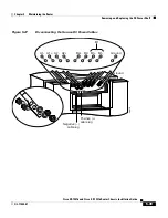
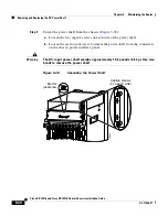
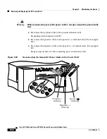
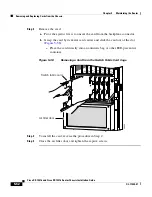
Disconnect each pair of power cables and the ground cable from the DC-input
terminal studs as follows (
Figure 5-27
):
Caution
Before removing cables, be sure to note the color for each type of cable (positive,
negative, and ground). Because there is no color code standard for source DC
wiring, you must be sure which power cables are connected to the proper positive
(+) and negative (–) terminal studs. Typically, green (or green and yellow)
indicate a ground cable, while power cable leads may be labeled positive (+) or
negative (–). Because this is not always the case, the safest way to indicate the
polarity of a cable is to note its color and identify it as described in this procedure.
Warning
When disconnecting source DC power cables, always disconnect the ground
cable last.
Beginning with terminal studs A1 (
Figure 5-27
):
a.
Remove the nut and washer from the negative (–) terminal studs and
disconnect the cable.
•
Label the cable. For example: A1-.
b.
Remove the nut and washer from the positive (+) terminal studs and
disconnect the cable.
•
Label the cable. For example: A1+.
Repeat steps
a
. and
b.
for the remaining pairs of terminal studs.
c.
After all power cables are disconnected, remove the nut and washer from the
ground terminal studs and disconnect the ground cable.
•
Label the cable as “ground”.

