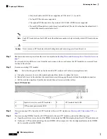
c) Push down evenly on the top corners of the DIMM until it is fully seated and the ejector levers on both ends lock
into place.
Step 5
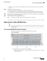
Install a new CPU module to the chassis:
a) With the two ejector levers open, align the new CPU module with an empty bay.
b) Push the module into the bay until it engages with the midplane connectors and is flush with the chassis front.
c) Rotate both ejector levers toward the center until they lay flat and their latches lock into the front of the module.
Step 6
Reconnect power cords to all power supplies and then allow the server to boot to standby power mode (indicated when
the front panel Power button LED lights amber).
Step 7
Fully power on the server by pressing the Power button.
Verify that the power LED on the front of the CPU module returns to solid green.
Note
Replacing Front-Loading SAS/SATA Drives
You do not have to shut down the server or drive to replace SAS/SATA hard drives or SSDs because they
are hot-swappable.
Note
Front-Loading SAS/SATA Drive Population Guidelines
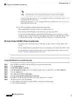
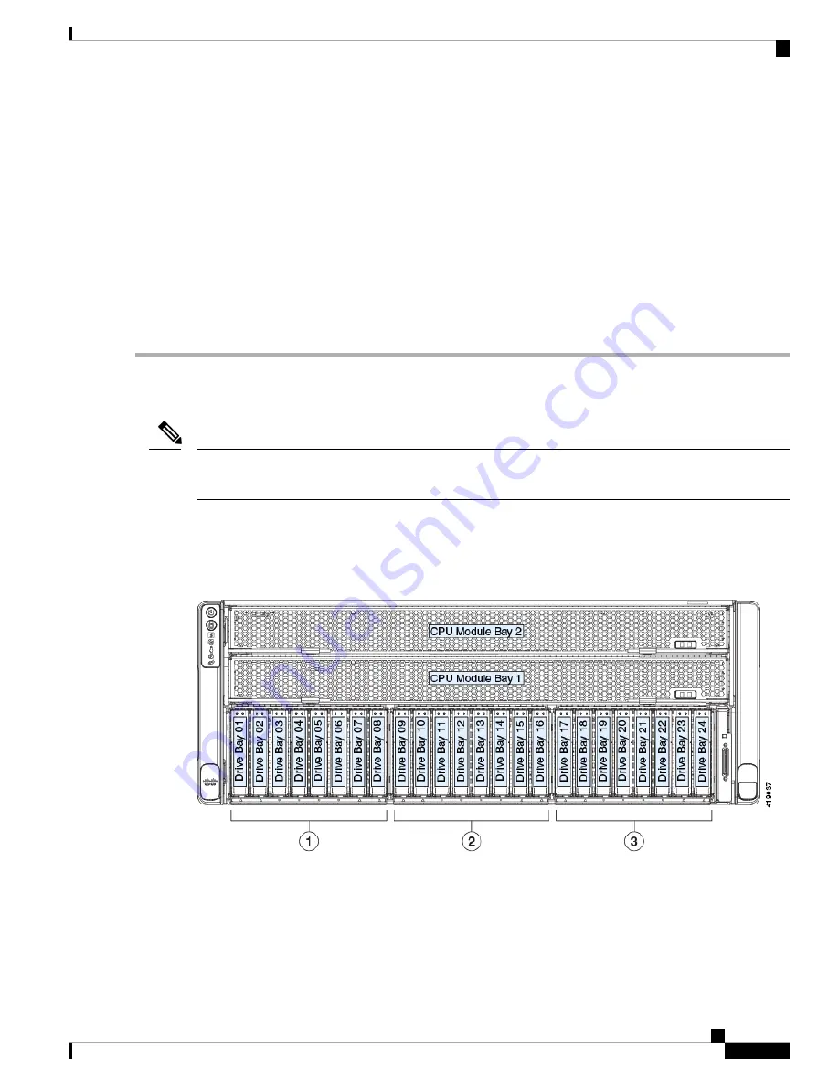
The front drives in the server are installed into three removable drive bay modules.
Figure 9: Drive Bay Numbering
• SAS/SATA/NVMe drive bay modules (UCSC-C480-8HDD):
• Left drive bay module: Bays 1, 2, 7, 8 support SAS/SATA or NVMe drives; bays 3, 4, 5, 6 support
SAS/SATA drives only.
Maintaining the Server
19
Maintaining the Server
Replacing Front-Loading SAS/SATA Drives


