


You do not have to pull the server out of the rack or remove the server cover because the CPU modules
are accessible from the front of the server.
Note
Step 2
Remove an existing CPU module from the chassis:
Verify that the power LED on the front of the CPU module is off before removing the module.
Note
a) Grasp the two ejector levers on the front of the CPU module and pinch their latches to release the levers.
b) Rotate both levers to the outside at the same time to evenly disengage the module from the midplane connectors.
c) Pull the module straight out from the chassis and then set it on an antistatic surface.
Step 3
Remove an existing DCPMM:
If you are moving DCPMMs with active data (persistent memory) from one server to another as in an RMA
situation, each DCPMM must be installed to the identical position in the new server. Note the positions of each
DCPMM or temporarily label them when removing them from the old server.
Caution
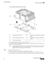
a) Locate the DCPMM that you are removing, and then open the ejector levers at each end of its DIMM slot.
b) Lift straight up on the DCPMM and set it aside.
Step 4
Install a new DCPMM:
Before installing DCPMMs, see the population rules for this server:
Intel Optane DC Persistent Memory Module
Population Rules and Performance Guidelines, on page 86
Note
a) Align the new DCPMM with the empty slot on the motherboard. Use the alignment feature in the DIMM slot to
correctly orient the DCPMM.
b) Push down evenly on the top corners of the DCPMM until it is fully seated and the ejector levers on both ends lock
into place.
Step 5
Return the CPU module to the chassis:
a) With the two ejector levers open, align the CPU module with an empty bay.
b) Push the module into the bay until it engages with the midplane connectors and is flush with the chassis front.
c) Rotate both ejector levers toward the center until they lay flat and their latches lock into the front of the module.
Step 6
Reconnect power cords to all power supplies and then allow the server to boot to standby power mode (indicated when
the front panel Power button LED lights amber).
Step 7
Fully power on the server by pressing the Power button.
Verify that the power LED on the front of the CPU module returns to solid green.
Note
Step 8
Perform post-installation actions:
• If the existing configuration is in 100% Memory mode, and the new DCPMM is also in 100% Memory mode (the
factory default), the only action is to ensure that all DCPMMs are at the latest, matching firmware level.
• If the existing configuration is fully or partly in App-Direct mode and new DCPMM is also in App-Direct mode,
then ensure that all DCPMMs are are at the latest matching firmware level and also re-provision the DCPMMs by
creating a new goal.
• If the existing configuration and the new DCPMM are in different modes, then ensure that all DCPMMs are are at
the latest matching firmware level and also re-provision the DCPMMs by creating a new goal.
There a number of tools for configuring goals, regions, and namespaces.
Maintaining the Server
88
Maintaining the Server
Installing Intel Optane DC Persistent Memory Modules


