1-18
Cisco Catalyst Blade Switch 3120 for HP Software Configuration Guide
OL-12247-01
Chapter 1 Overview
Network Configuration Examples
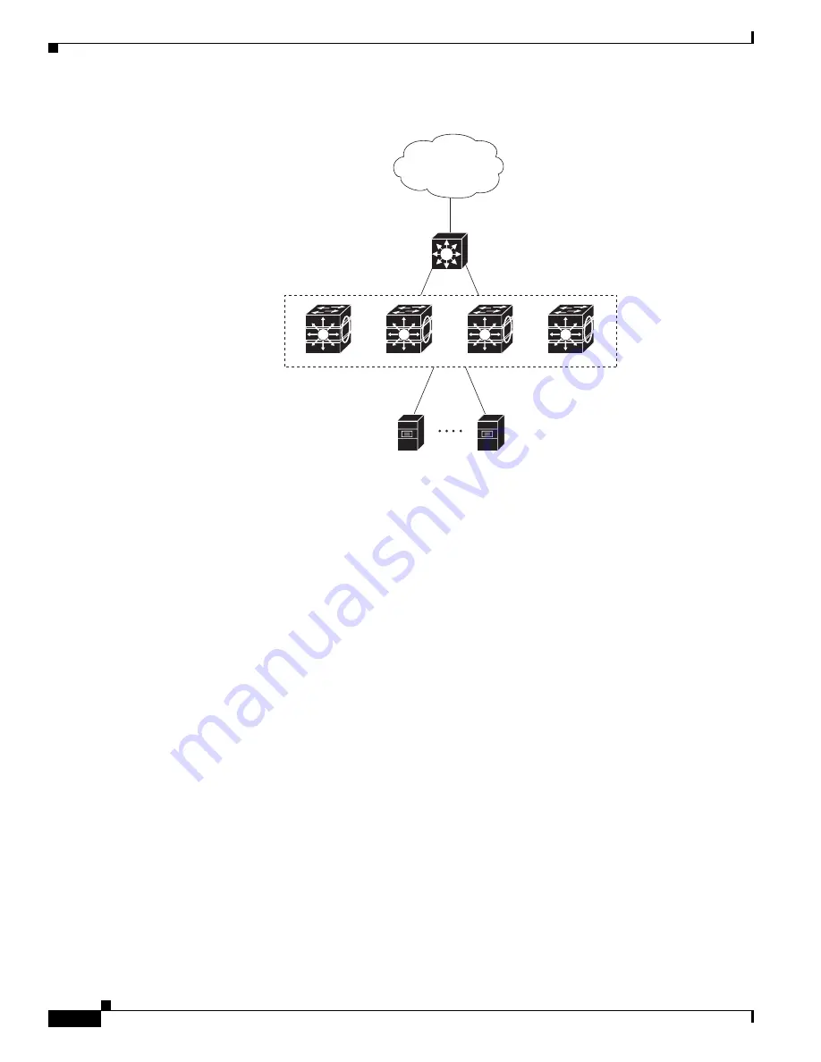
Figure 1-1
Data Center
•
Expanded data center (
Figure 1-2
)—You can use standalone switches and switch stacks to
interconnect groups of servers, centralizing physical security and administration of your network.
For high-speed IP forwarding at the distribution layer, connect the switches in the access layer to
multilayer switches with routing capability. The Gigabit interconnections minimize latency in the
data flow.
QoS and policing on the switches provide preferential treatment for certain data streams. They
segment traffic streams into different paths for processing. Security features on the switch ensure
rapid handling of packets.
Fault tolerance from the server racks to the core is achieved through dual homing of servers
connected to dual switch stacks or the switches, which have redundant Gigabit EtherChannels and
cross-stack EtherChannels.
Using dual SFP module uplinks from the switches provides redundant uplinks to the network core.
Using SFP modules provides flexibility in media and distance options through fiber-optic
connections.
The various lengths of stack cable available, ranging from 0.5 meter to 3 meters, provide extended
connections to the switch stacks across multiple server racks, for multiple stack aggregation.
Si
2
01756
Catalyst
4500 or 6500
multilayer switch
Distribution layer
Access layer
Blade servers
Blade switch
Layer 3 StackWise Plus
switch stack
Core


