WM8940
30
Rev 4.4
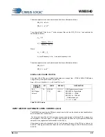
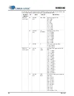
The ALC has two modes selected by the ALCMODE register: normal mode and peak limiter mode.
The ALC/limiter function is enabled by setting the register bit R32[8] ALCSEL.
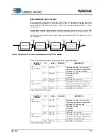
REGISTER
ADDRESS
BIT
LABEL
DEFAULT
DESCRIPTION
R32 (20h)
ALC Control 1
2:0
ALCMIN
[2:0]
000 (-12dB)
Set minimum gain of PGA
000 = -12dB
001 = -6dB
010 = 0dB
011 = +6dB
100 = +12dB
101 = +18dB
110 = +24dB
111 = +30dB
5:3
ALCMAX
[2:0]
111
(+35.25dB)
Set Maximum Gain of PGA
111 = +35.25dB
110 = +29.25dB
101 = +23.25dB
100 = +17.25dB
011 = +11.25dB
010 = +5.25dB
001 = -0.75dB
000 = -6.75dB
8
ALCSEL
0
ALC function select (see Note)
0 = ALC disabled
1 = ALC Enabled
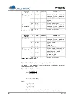
R33 (21h)
ALC Control 2
3:0
ALCLVL
[3:0]
1011
(-6dB)
ALC target
– sets signal level at ADC
input
1111 = -1.5dBFS
1110 = -1.5dBFS
1101 = -3dBFS
1100 = -4.5dBFS
1011 = -6dBFS
1010 = -7.5dBFS
1001 = -9dBFS
1000 = -10.5dBFS
0111 = -12dBFS
0110 = -13.5dBFS
0101 = -15dBFS
0100 = -16.5dBFS
0011 = -18dBFS
0010 = -19.5dBFS
0001 = -21dBFS
0000 = -22.5dBFS
7:4
ALCHLD
[3:0]
0000
(0ms)
ALC hold time before gain is increased.
0000 = 0ms
0001 = 2.67ms
0010 = 5.33ms
0011 = 10.66ms
0100 = 21.32ms
0101 = 42.64ms
0110 = 85.28ms
0111 = 0.17s
1000 = 0.34s
1001 = 0.68s
1010 or higher = 1.36s


