


WM8940
62
Rev 4.4
REGISTER
ADDRESS
BIT
LABEL
DEFAULT
DESCRIPTION
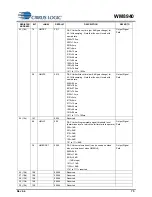
R8
GPIO
control
7
MODE_GPIO
0
Selects MODE as a GPIO pin
0 = MODE is an input. MODE selects 2-
wire mode when low and 3-wire mode
when high.
1 = MODE can be an input or output
under the control of the GPIO control
register. Interface operates in 3-wire mode
regardless of what happens on the MODE
pin.
Table 54 Mode is GPIO Control
Auto-incremental writes are supported in 2 wire and 3 wire modes. This is enabled by default.
REGISTER
ADDRESS
BIT
LABEL
DEFAULT
DESCRIPTION
R9
Control
Interface
1
AUTOINC
1
Auto-Incremental write enable
0=Auto-Incremental writes disabled
1=Auto-Incremental writes enabled
Table 55 Control Interface
3-WIRE SERIAL CONTROL MODE
In 3-wire mode, every rising edge of SCLK clocks in one data bit from the SDIN pin. A rising edge on
CSB/GPIO latches in a complete control word consisting of the last 16 bits.
B23
B20
B19
B18
B17
B16
B15
B14
B13
B4
B3
B2
B1
B0
SDIN
SCLK
CSB
control register address
control register data bits
latch
B21
B22
Figure 34 3-Wire Serial Control Interface
READBACK IN 3-WIRE MODE
The following two timing diagrams are also supported.
Figure 35 Alternative 3-Wire Serial Control Timing


