WM8940
Rev 4.4
73
REGISTER
ADDRESS
BIT
LABEL
DEFAULT
DESCRIPTION
REFER TO
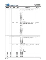
6
DACMU
0
DAC soft mute enable
0 = DACMU disabled
1 = DACMU enabled
Output Signal
Path
5:3
00
Reserved
2
AMUTE
0
DAC auto mute enable
0 = auto mute disabled
1 = auto mute enabled
Output Signal
Path
1
0
Reserved
0
DACPOL
0
DAC Polarity Invert
0 = No inversion
1 = DAC output inverted
Output Signal
Path
11 (0Bh)
15:8
00h
Reserved
7:0
DACVOL
11111111
DAC Digital Volume Control
0000 0000 = Digital Mute
0000 0001 = -127dB
0000 0010 = -126.5dB
… 0.5dB steps up to
1111 1111 = 0dB
Output Signal
Path
12 (0Ch)
15:0
Reserved
13 (0Dh)
15:0
Reserved
14 (0Eh)
15:9
00h
Reserved
8
HPFEN
1
High Pass Filter Enable
0=disabled
1=enabled
Analogue to
Digital Converter
(ADC)
7
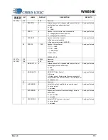
HPFAPP
0
Select audio mode or application mode
0=Audio mode (1
st
order, fc = ~3.7Hz)
1=Application mode (2
nd
order, fc = HPFCUT)
Analogue to
Digital Converter
(ADC)
6:4
HPFCUT
000
Application mode cut-off frequency
See Table 14 for details.
Analogue to
Digital Converter
(ADC)
3:1
00
Reserved
0
ADCPOL
0
ADC Polarity
0=normal
1=inverted
Analogue to
Digital Converter
(ADC)
15 (0Fh)
15:8
00h
Reserved
7:0
ADCVOL
11111111
ADC Digital Volume Control
0000 0000 = Digital Mute
0000 0001 = -127dB
0000 0010 = -126.5dB
... 0.5dB steps up to
1111 1111 = 0dB
Analogue to
Digital Converter
(ADC)
16 (10h)
15
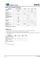
NF0_UP
0
Notch filter 0 update. The notch filter 0 values used
internally only update when one of the NF0_UP bits is
set high.
Analogue to
Digital Converter
(ADC)
14
NF0_EN
0
Notch filter 0 enable:
0=Disabled
1=Enabled
Analogue to
Digital Converter
(ADC)
13:0
NF0_A0
0000h
Notch Filter 0 a0 coefficient
Analogue to
Digital Converter
(ADC)
17 (11h)
15
NF0_UP
0
Notch filter 0 update. The notch filter 0 values used
internally only update when one of the NF0_UP bits is
set high.
Analogue to
Digital Converter
(ADC)
14
0
Reserved


