WM8940
84
Rev 4.4
-40
+0
-35
-30
-25
-20
-15
-10
-5
R
E
S
P
O
N
S
E
(dB)
20
20k
50
100
200
500
1k
2k
5k
10k
Frequency (Hz)
T
T
T
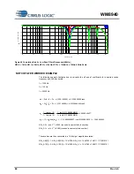
Figure 48 Cumulative Notch + Low Pass Filters Responses (48kHz);
NF0 fc = 1kHz; NF1 fc = 5kHz; NF2 fc = 10kHz; LPF fc = 11kHz; fb = 100Hz, 600Hz, 2kHz
NOTCH FILTER WORKED EXAMPLE
The following example illustrates how to calculate the a0 and a1 coefficients for a desired centre
frequency and -3dB bandwidth.
f
c
= 1000 Hz
f
b
= 100 Hz
f
s
= 48000 Hz
s
c
0
f
/
f
2
w
=
=
2
x (1000 / 48000) = 0.1308996939 rads
s
b
b
f
/
f
2
w
=
=
2
x (100 / 48000) = 0.01308996939 rads
)
2
/
w
tan(
1
)
2
/
w
tan(
1
a
b
b
0
+
−
=
=
)
2
/
9
0130899693
.
0
tan(
1
)
2
/
9
0130899693
.
0
tan(
1
+
−
= 0.9869949627
)
w
cos(
)
a
1
(
a
0
0
1
+
−
=
=
)
1308996939
.
0
cos(
)
9869949627
.
0
1
(
+
−
= -1.969995945
NFn_A0 = -a0 x 2
13
= -8085 (rounded to nearest whole number)
NFn_A1 = -a1 x 2
12
= 8069 (rounded to nearest whole number)
These values are then converted to a 14-bit sign / magnitude notation:
NFn_A0[13] = 1; NFn_A0[12:0] = 13’h1F95; NFn_A0 = 14’h3F95 = 14’b11111110010101
NFn_A1[13] = 0; NFn_A1[12:0] = 13’h1F85; NFn_A1 = 14’h1F85 = 14’b01111110000101


