WM8940
Rev 4.4
29
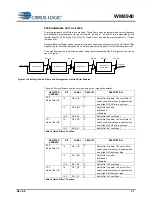
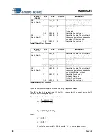
The actual register values can be determined from the coefficients as follows:
NFn_A0 = -a0 x 2
13
NFn_A1 = -a1 x 2
12
To configure Notch Filter 3 as a 1
st
order low pass filter, set the NF3_LP bit to 1 and calculate the
coefficients as follows:
0
0
=
a
1
)
2
/
tan(
1
)
2
/
tan(
1
+
−
=
c
c
w
w
a
Where:
s
c
c
f
f
w
/
2
=
f
c
= cutoff frequency in Hz,
f
s
= sample frequency in Hz
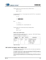
The actual register values can be determined from the coefficients as follows:
NF3_A0 = 0
NF3_A1 = -a
1
x2
12
DIGITAL ADC VOLUME CONTROL
The output of the ADCs can be digitally attenuated over a range from
–127dB to 0dB in 0.5dB steps.
The gain for a given eight-bit code X is given by:
Gain = 0.5 x (x
–255) dB for 1
x
255, MUTE for x = 0
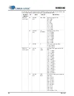
REGISTER
ADDRESS
BIT
LABEL
DEFAULT
DESCRIPTION
R15
ADC Digital
Volume
7:0
ADCVOL
[7:0]
11111111
( 0dB )
ADC Digital Volume Control
0000 0000 = Digital Mute
0000 0001 = -127dB
0000 0010 = -126.5dB
... 0.5dB steps up to
1111 1111 = 0dB
Table 19 ADC Volume
INPUT LIMITER / AUTOMATIC LEVEL CONTROL (ALC)
The WM8940 has an automatic PGA gain control circuit, which can function as an input peak limiter or
as an automatic level control (ALC).
The Automatic Level Control (ALC) provides continuous adjustment of the input PGA in response to
the amplitude of the input signal. A digital peak detector monitors the input signal amplitude and
compares it to a register defined threshold level (ALCLVL).
If the signal is below the threshold, the ALC will increase the gain of the PGA at a rate set by
ALCDCY. If the signal is above the threshold, the ALC will reduce the gain of the PGA at a rate set by
ALCATK.


