OG_MU2-ESP_v10e
10
Circuit Design, Inc.
OPERATION GUIDE
■
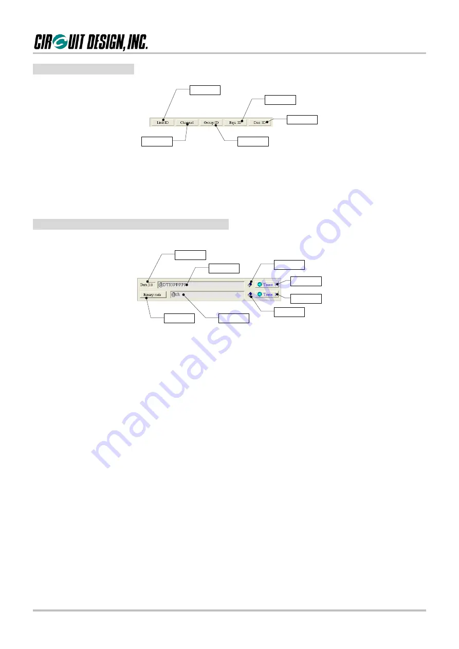
2.2.2 ID setting panel
1
2
3
4
5
[1] Link ID check button
Clicking this button issues link related commands, making it possible to check the internal setting values.
[2] Channel, [3] Group ID, [4] Equipment ID, [5] Destination ID
You can change the link related IDs without writing the commands.
■
2.2.3 Command and data transmission panel
1
2
3
4
5
6
7
8
[1] Data input line 1 counter
Indicates the amount of data (single byte) entered in the data input line 1.
[2] Data input line 1
Enter commands or data, and press the Enter key or click the “Trans.1” button to send the data to the MU-2-R.
Mainly used to enter the data transmit commands. The content is cleared with a double mouse click.
In the command mode: Enter commands.
In the text mode and binary mode: Enter transmission data.
[3] Clear data input line 1 button
Clears the content of the data input line 1. The SHIFT+F8 function key has the same function.
[4] Transmit 1 button
Transmits the content of the data input line 1 to the MU-2-R. The F8 function key has the same function.
If commands and so on are not sent normally when you click the “Trans. 1” button, click the
COM port button
again.
[5] Transmit 2 button
Transmits the content of the data input line 2 to the MU-2-R. The F9 function key has the same function.
If commands and so on are not sent normally when you click the “Trans. 2” button, click the
COM port button
again.
[6] Clear data input line 2 button
Clears the content of the data input line 2. The SHIFT+F9 function key has the same function.
[7] Data input line 2
Enter commands or data, and press the Enter key or click the “Trans. 2” button to send the data to the MU-2-R.
The content is cleared with a double mouse click.
In the command mode: Enter commands.
In the text mode and binary mode: Enter transmission data.
[8]Binary code transmission button
Opens a binary code transmission form to send binary codes. For details, refer to the explanation of the binary
code transmission form.


