background image

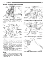
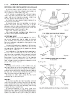
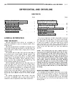
(6) Position a transmission jack and wooden block

under the center of the rear suspension crossmember
to support and lower crossmember during removal
(Fig. 37).

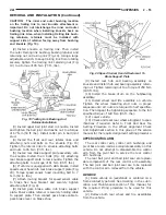
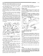
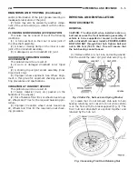
(7) If vehicle is equipped with antilock brakes,

remove routing clips for wheel speed sensor cable
from brackets on upper control arm (Fig. 38).

(8) Remove the nuts and bolts on each side of vehi-

cle attaching the 4 lateral links to the knuckles.

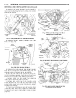
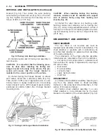
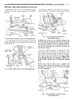
(9) Remove the 4 bolts attaching the rear suspen-

sion crossmember to rear frame rails (Fig. 39).

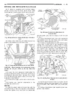
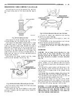
(10) Lower

the

rear

suspension

crossmember

enough to access the upper control arm pivot bar to
crossmember attaching bolts (Fig. 40). Remove the 4
bolts attaching the upper control arms to the suspen-
sion crossmember. Remove the control arms from the
crossmember.

(11) Lower the rear suspension crossmember, lat-

eral arms and stabilizer bar as far as possible using

the transmission jack. Then with the aid of a helper
remove rear suspension crossmember from the vehi-
cle.

(12) Transfer

the

lateral

arms,

stabilizer

bar

mounting brackets and the stabilizer bar and bush-
ings to the replacement crossmember before install-
ing the replacement crossmember in the vehicle.
Tighten the stabilizer bar mounting bracket to rear
crossmember mounting bolts to a torque of 27 N·m
(20 ft. lbs.).Tighten the 4 lateral arm to crossmember
attaching bolts to a torque of 95 N·m (80 ft. lbs.).
Install the lateral arm to crossmember bolts so
head of bolt will be toward the front of the
vehicle when the crossmember is installed.

INSTALL

(1) Install the rear suspension crossmember, lat-

eral arms and rear stabilizer bar back into the vehi-
cle as an assembly.

Fig. 37 Lowering And Supporting Rear

SuspensionCrossmember

WOODENBLOCK

TRANSMISSION

JACK

REAR SUSPENSION CROSS-

MEMBER

Fig. 38 Speed Sensor Cable Attachment ToControl

Arm

UPPER

CONTROL

ARM

SHOCK ABSORBER

SPEED SENSOR CABLE ROUTING

CLIPS

BOLT

SPEED

SENSOR

CABLE

BRAKE FLEX HOSE

BRACKET

BOLT

BRAKE DRUM

Fig. 39 Suspension Crossmember AttachmentTo

Frame Rails

ATTACHING

BOLTS

ATTACHING

BOLTS

REAR SUSPENSION CROSS-

MEMBER

Fig. 40 Upper Control Arm Attachment To

Crossmember

SHOCK ABSORBER

ATTACHING BOLTS

UPPER CONTROL ARM PIVOT

BAR

REAR SUSPENSION CROSS-

MEMBER

UPPER CONTROL ARM

2 - 58

SUSPENSION

JA

REMOVAL AND INSTALLATION (Continued)

Содержание Stratus LHD 1997

Страница 1: ...Welcome to the 1997 Stratus RHD LHD Interactive Electronic Service Manual CLICK ON VEHICLE TO BEGIN tweddle litho dom parts cdrom demo 09 96 page 1 output 0908 ET 05 27 97 ...

Страница 2: ...vehi cles that are operated under the conditions listed at the beginning of the Maintenance Schedule section Use the schedule that best describes your driving conditions Where time and mileage are listed follow the interval that occurs first PARTS AND LUBRICANT RECOMMENDATIONS When service is required Chrysler Corporation recommends that only Mopart brand parts lubri cants and chemicals be used Mo...

Страница 3: ...ts In addition API classification defines the lubricants usage LUBRICANTS AND GREASES Lubricating grease is rated for quality and usage by the NLGI All approved products have the NLGI symbol Fig 3 on the label At the bottom NLGI symbol is the usage and quality identification letters Wheel bearing lubricant is identified by the letter G Chassis lubricant is identified by the latter L The letter fol...

Страница 4: ...n severe operating conditions such as dusty areas and very short trip driving UNSCHEDULED INSPECTION At Each Stop For Fuel Check engine oil level add as required Check windshield washer solvent and add if required Once A Month Check tire pressure and look for unusual wear or damage Check fluid levels of coolant reservoir power steering and automatic transmission and add as required Check all light...

Страница 5: ...months since last change 82 500 Miles 132 000 km or at 66 months Change engine oil Replace engine oil filter on 2 0 liter and 2 4 liter engines Flush and replace engine coolant if it has been 30 000 miles 48 000 km or 24 months since last change 90 000 Miles 144 000 km or at 72 months Change engine oil Replace engine oil filter on all engines Check and replace if necessary the PCV valve Lubricate ...

Страница 6: ...e oil filter on all engines 45 000 Miles 72 000 km Change engine oil Replace engine oil filter on 2 0 liter and 2 4 liter engines Adjust drive belt tension Change automatic transaxle fluid and filter 48 000 Miles 77 000 km Change engine oil Replace engine oil filter on all engines Inspect front brake pads and rear brake linings 51 000 Miles 82 000 km Change engine oil Replace engine oil filter on ...

Страница 7: ...front and rear suspension upper ball joints Adjust drive belt tension Replace air cleaner element Replace spark plugs on 2 0 liter and 2 4 liter engines Change automatic transaxle fluid and filter 93 000 Miles 149 000 km Change engine oil Replace engine oil filter on 2 0 liter and 2 4 liter engines 96 000 Miles 154 000 km Change engine oil Replace engine oil filter on all engines Inspect front bra...

Страница 8: ...ause of starting problem on dis abled vehicle is severe damage to booster vehicle charging system can result 2 When using another vehicle as a booster source park the booster vehicle within cable reach Turn off all accessories set the parking brake place the automatic transmission in PARK or the manual transmission in NEUTRAL and turn the ignition OFF 3 On disabled vehicle place gear selector in p...

Страница 9: ... dolly If a flat bed device is used the approach angle should not exceed 15 degrees GROUND CLEARANCE CAUTION If vehicle is towed with wheels removed install lug nuts to retain brake drums or rotors A towed vehicle should be raised until the lifted wheels are a minimum 100 mm 4 in from the ground Be sure there is at least 100 mm 4 in clearance between the tail pipe and the ground If necessary remov...

Страница 10: ...bles to suspension components or engine mounts damage to vehicle can result JA vehicles can be tied to a flat bed device using the reinforced loops located under the front and rear bumpers on the drivers side of the vehicle There are also four reinforced elongated holes for T or R hooks located on the bottom of the front frame rail torque boxes behind the front wheels and forward of the rear wheel...

Страница 11: ......

Страница 12: ...curacy of the alignment except alignment specifi cations recommended by Chrysler Corporation MUST ALWAYS be used CAUTION Do not attempt to modify any suspen sion or steering components by heating or bending of the component Wheel alignment adjustments should always be made in the following sequence to ensure that an accurate alignment is performed 1 Adjust rear camber to be at the prefered set tin...

Страница 13: ...Fig 1 Alignment Camber Toe LOOSEN NUT TO ADJUST TOE ADJUST TOE NEGATIVE POSITIVE CAMBER TOE TOE OUT TOE IN FRONT 2 2 SUSPENSION JA DESCRIPTION AND OPERATION Continued ...

Страница 14: ...ct Wheel Alignment 2 Check And Reset Wheel Alignment 3 Worn Tires 3 Replace Tires Front End Growl Or Grinding With Vehicle Going Straight At A Constant Speed 1 Engine Mount Grounding 1 Reposition Engine As Required 2 Worn Or Broken C V Joint 2 Replace C V Joint Front End Whine When Accelerating Or Decelerating 1 Worn Or Defective Transaxle Gears Or Bearings 1 Replace Transaxle Gears Or Bearings Fr...

Страница 15: ...in good condition and have approximately the same wear Note the type of tread wear which will aid in diagnosing see Wheels and Tires Group 22 2 Check front wheel and tire assembly for radial runout 3 Inspect lower ball joints and all steering link age for looseness 4 Check for broken or sagged front and rear springs 5 Check vehicle ride height to verify it is within specifications 6 Alignment MUST...

Страница 16: ...tion CAUTION Do not attempt to straighten or repair a lateral link Do not apply heat to the lateral link adjusting screws or to the jam nuts Fig 2 when loosening or adjusting the lateral links 3 Loosen the adjusting screw jam nuts Fig 2 on all 4 of the rear lateral arm adjusting screws CAUTION Do not attempt to move the adjusting screws without properly loosening the jam nuts Note that each adjust...

Страница 17: ...front inner to outer tie rod end jam nuts Fig 4 Grasp inner tie rods at serrations Fig 4 and rotate inner tie rods of steering gear to set front Toe to the preferred Toe specification See Alignment Specifications in this group of the service manual for preferred specification 8 Tighten tie rod locknuts Fig 4 to 61 N m 45 ft lbs torque 9 Adjust steering gear to tie rod boots Fig 4 at inner tie rod ...

Страница 18: ...CCEPTABLE ALIGNMENT RANGE AT CURB HEIGHT PREFERRED SETTING CAMBER 0 6 to 0 2 0 2 TOE RIGHT LEFT 0 05 out to 0 15 in 0 05 in TOTAL TOE Specified In Degrees See Note TOE OUT When Backed On Alignment Rack Is TOE In When Driving 0 1 out to 0 3 in 0 1 in THRUST ANGLE or 0 15 0 0 Note Total Toe is the arithmetic sum of the left and right wheel Toe settings Positive is Toe in negative is Toe out Total To...

Страница 19: ...ONS 42 SPECIAL TOOLS FRONT SUSPENSION 43 GENERAL INFORMATION GENERAL INFORMATION CAUTION ONLY FRAME CONTACT HOISTING EQUIPMENT CAN BE USED ON THIS VEHICLE All vehicles have a fully independent rear suspension The vehicles can not be hoisted using equipment designed to lift a vehicle by the rear axle If this type of hoisting equipment is used damage to rear suspension components will occur CAUTION ...

Страница 20: ...between an upper seat located just below the top shock absorber mounting bracket and a lower spring seat located on the shock absorber The top of each shock absorber assembly is bolted to the cast aluminum upper control arm bracket which is then bolted to the shock tower of the vehicle using 4 mounting bolts The bottom of the shock absorber assembly attaches to the lower control arm of the vehicle...

Страница 21: ...otter pin is used for positive retention of the castle nut The lower ball joint is lubricated for life at the time it is assembled in the lower control arm The ball joint does not require any type of addi tional lubrication for the life of the vehicle No attempt should be made to ever add any lubri cation to the lower ball joint UPPER CONTROL ARM BALL JOINT The ball joint is pressed into the upper...

Страница 22: ...o be used for this vehicle 2 Install a dial indicator on the vehicle so it is contacting the top surface of the steering knuckle near the lower ball joint stud castle nut 3 Grab wheel and tire assembly and push it up and down firmly 4 Record the amount of up and down movement of the steering knuckle recorded on the dial indicator 5 Replace lower control arm if the movement in the lower control arm...

Страница 23: ... position toward the rear of the front wheel opening 8 Remove pinch bolt attaching shock absorber clevis to shock absorber Fig 6 9 Remove the thru bolt Fig 7 attaching the shock absorber clevis to the lower control arm 10 Remove the clevis from the shock absorber by carefully tapping the clevis off the shock absorber using a soft brass drift 11 Remove the 4 bolts Fig 8 attaching the shock absorber...

Страница 24: ...ud Tighten castle nut to a torque of 62 N m 45 ft lbs Install cotter pin in stud of ball joint Fig 4 5 Install the routing bracket for the speed control cable Fig 3 on the steering knuckle Install and securely tighten the routing bracket attaching bolt Fig 3 CAUTION When supporting lower control arm with jack stand do not position jack stand under the ball joint cap on the lower control arm Positi...

Страница 25: ...cotter pin and castle nut Fig 12 from the upper ball joint stud 5 Remove the upper ball joint stud from the steering knuckle using Puller Special Tool C 3894 A Fig 13 Pull steering knuckle outward and position toward the rear of the front wheel opening 6 Remove bolt Fig 14 attaching shock absorber clevis to the shock absorber Fig 11 Wheel Speed Sensor Cable RoutingBracket WHEEL SPEED SEN SOR CABLE...

Страница 26: ...ition Fig 17 WARNING DO NOT REMOVE SHOCK ABSORBER ROD NUT BEFORE SHOCK ABSORBER COIL SPRING IS COMPRESSED REMOVING SPRING TENSION FROM UPPER CONTROL ARM SHOCK ABSORBER MOUNTING BRACKET WARNING WHEN COMPRESSING COIL SPRING FOR REMOVAL FROM SHOCK ABSORBER THE FIRST FULL TOP AND BOTTOM COIL OF THE COIL SPRING MUST BE CAPTURED BY THE JAWS OF THE COIL SPRING COMPRESSOR 12 Compress shock absorber coil s...

Страница 27: ...er con trol arm mounting bracket 17 Remove the shock absorber rod lower isolator bushing and sleeve Fig 23 from the shock absorber upper control arm mounting bracket Then remove upper spring isolator Fig 23 from mounting bracket Fig 19 Shock Absorber Shaft Nut Removal SHOCK ABSORBER SOCKET SNAP ON A136 CROW FOOT Fig 20 Shock Absorber Rod Upper Washer SHOCK ABSORBER UPPER CONTROL ARM MOUNTING BRACK...

Страница 28: ... removed from the spring compressor remove it from the shock absorber assembly 9 Remove the shock absorber assembly from the vise and remove the clevis from the shock absorber 10 Install shock absorber assembly with the cle vis bracket removed into the shock tower Align the 2 locating pins and the 4 mounting holes on the upper control arm shock absorber mount with the holes in shock tower Install ...

Страница 29: ... this manual for the required lifting procedure to be used for this vehicle 2 Remove the tire and wheel assembly from the vehicle 3 If the vehicle is equipped with 15 inch wheels the heat shield Fig 28 will need to be removed before the lower control arm can be separated from the steering knuckle Use the following procedure to remove the heat shield 4 Remove the 2 bolts attaching the disc brake ca...

Страница 30: ...eleasing it from the ball joint can separate inner C V joint See Driveshafts 9 Remove the shock absorber clevis to lower con trol arm bushing thru bolt Separate clevis from lower control arm Fig 33 Fig 29 Disc Brake Caliper Mounting DISC BRAKE CALI PER ASSEMBLY STEERING KNUCKLE CALIPER ASSEMBLY GUIDE PIN BOLTS Fig 30 Stored Disc Brake Caliper ABS SPEED SEN SOR CABLE STEERING KNUCKLE ROTOR UPPER CO...

Страница 31: ...om the front suspension crossmember When removing rear of lower control arm from crossmem ber keep control arm as level as possible This will keep rear bushing from binding on crossmember making it easier to remove control arm from cross member INSTALL 1 Position rear of lower control arm into front suspension crossmember first Then install front of lower control arm in front suspension crossmembe...

Страница 32: ...and bolt Fig 37 to a torque of 182 N m 135 ft lbs 11 If vehicle is equipped with 15 inch wheels the heat shield Fig 28 MUST be installed on steering knuckle and mounting bolts securely tighten before rotor and caliper is installed on steering knuckle 12 Install rotor on hub bearing assembly 13 Install disc brake caliper on steering knuckle Install and tighten the disc brake caliper mounting bolts ...

Страница 33: ...d Fig 44 from lower control arm Heat shield must be removed before attempting to separating ball joint stud from steering knuckle Fig 40 Loosening Front Hub Nut FRONT HUB Fig 41 Front Disc Brake Caliper Mounting DISC BRAKE CALI PER ASSEMBLY STEERING KNUCKLE CALIPER ASSEMBLY GUIDE PIN BOLTS Fig 42 Disc Brake Caliper Removal InstallationOn Steering Knuckle ROTOR DISC BRAKE CALI PER ASSEMBLY OUTBOARD...

Страница 34: ...g 49 until steering knuckle separates from stud of lower ball joint When striking steering knuckle care MUST be taken not to hit lower control arm or ball joint grease seal CAUTION Pulling steering knuckle out from vehi cle after releasing from ball joint can separate inner C V joint See Driveshafts 15 Lift up on steering knuckle separating it from the lower ball joint stud Use caution when sepa r...

Страница 35: ...ring assembly Then install steering knuckle onto the ball joint stud in lower control arm 3 Install the steering knuckle to lower ball joint stud castle nut 4 Install upper ball joint in steering knuckle Install the steering knuckle to upper ball joint nut Tighten the upper ball joint castle nut Fig 51 to a torque of 62 N m 45 ft lbs Then using a crowfoot and torque wrench tighten the lower ball j...

Страница 36: ...kle Caliper is installed by first sliding top of caliper under top abutment on steering knuckle Then installing bottom of caliper against bottom abutment of steering knuckle Fig 42 10 Install disc brake caliper assembly to steering knuckle guide pin bolts Fig 41 Tighten caliper assembly guide pin bolts to a torque of 31 N m 23 ft lbs 11 Clean all foreign matter from the threads of the outer C V jo...

Страница 37: ...r Install the stabi lizer bar bushing retainer to crossmember and body attaching bolts Fig 58 2 Align stabilizer bar attaching link assemblies with attaching link mounting holes in the lower con trol arms Install stabilizer bar attaching links into both lower control arms Install the attaching link to lower control arm retaining nuts Torque the stabi lizer bar attaching link nuts to 105 N m 78 ft ...

Страница 38: ... brake caliper assembly from steer ing knuckle Caliper is removed by first lifting bot tom of caliper away from steering knuckle and then removing top of caliper out from under steering knuckle Fig 62 7 Support brake caliper adapter assembly using a wire hook Fig 63 and not by hydraulic hose Fig 59 Cotter Pin Nut Lock HUB NUT NUT LOCK COTTER PIN SPRING WASHER Fig 60 Loosening Front Hub Nut FRONT H...

Страница 39: ...ock brakes remove the speed sensor cable routing bracket Fig 67 from the steering knuckle 13 Remove cotter pin and castle nut Fig 68 from the stud of the lower ball joint Fig 64 Ball Joint Heat Shield With 15 InchWheels LOWER CON TROL ARM HEAT SHIELD BALL JOINT Fig 65 Removing Tie Rod End Attaching Nut TIE ROD END HEAT SHIELD STEERING KNUCKLE TIE ROD END STUD NUT Fig 66 Tie Rod End Removal From St...

Страница 40: ...oint during this operation Do not allow driveshaft to hang by inner C V joint driveshaft must be supported 16 Separate the steering knuckle from the outer C V joint Separate steering knuckle from outer C V joint by supporting the driveshaft while pulling steering knuckle away from the outer C V joint Fig 70 17 Remove the cotter pin and nut Fig 71 from the upper ball joint stud to steering knuckle ...

Страница 41: ...acket on the steering knuckle Fig 67 and securely tighten attaching bolt CAUTION When installing tie rod on steering knuckle the heat shield Fig 74 must be installed If heat shield is not installed tie rod seal boot can fail due to excessive heat from brake rotor 5 Install tie rod end into the steering knuckle Start tie rod end to steering knuckle attaching nut onto stud of tie rod end While holdi...

Страница 42: ...earing assembly does not require removal from the steering knuckle to replace wheel attaching studs in the hub and bearing assembly REMOVE 1 Raise vehicle on jackstands or centered on a frame contact type hoist See Hoisting in the Lubri cation and Maintenance section of this manual for the required lifting procedure to be used for this vehicle 2 Remove the front wheel and tire assembly from the ve...

Страница 43: ...ted against the bearing flange remove lug nut and washers from wheel stud 3 Install braking disk back on front hub Fig 81 4 Install disc brake caliper assembly on steering knuckle Caliper is installed by first sliding top of caliper under top abutment on steering knuckle Then installing bottom of caliper against bottom abutment of steering knuckle Fig 79 5 Install disc brake caliper assembly to st...

Страница 44: ...BER MOUNTING BRACKET WARNING WHEN COMPRESSING COIL SPRING FOR REMOVAL FROM SHOCK ABSORBER THE FIRST FULL TOP AND BOTTOM COIL OF THE COIL SPRING MUST BE CAPTURED BY THE JAWS OF THE COIL SPRING COMPRESSOR 3 Compress shock absorber coil spring using Professional Services Equipment Spring Compressor GP 2020 C3 5 fitted with the GP C42 upper spring shoe and GP A20 lower spring shoe Fig 85 4 Hold the ro...

Страница 45: ...or from mounting bracket 9 Remove the lower isolator bushing from the shock absorber rod sleeve 10 Remove washer from top of dust shield Fig 91 11 Remove the dust shield Fig 92 from the shock absorber assembly Fig 88 Shock Absorber Upper Control ArmMounting Bracket SHOCK ABSORBER CON TROL ARM MOUNTING BRACKET SHOCK ABSORBER SPRING COMPRES SOR Fig 89 Shock Absorber Rod Upper IsolatorBushing SHOCK A...

Страница 46: ...pection before re assembling the shock absorber ASSEMBLY CAUTION Do not clamp the shock absorber in a vise by the body of the shock absorber The clevis bracket must be reinstalled on the shock absorber clamped in the vise using the clevis bracket 1 Install clevis bracket back on replacement shock absorber and tighten pinch bolt Then using the clevis bracket clamp the shock absorber assem bly in a ...

Страница 47: ...ING COMPRES SOR GP 2020 C3 5 OR AN EQUIVALENT IS RELEASED FROM THE COIL SPRING 12 Install nut on rod of shock absorber assembly Install Shock Absorber Socket Snap On A136 or an equivalent on end of shock rod to keep rod from turn ing Fig 86 Then tighten rod nut using a crowfoot Fig 86 to a torque of 55 N m 40 ft lbs 13 Relieve all tension from spring compressor After all spring tension has been re...

Страница 48: ...nd replacement of the lower control arm isolator bushings the lower control arm must be removed from the vehicle DISASSEMBLY 1 Remove lower control arm assembly from vehi cle See Lower Control Arm Removal in this section of the service manual for the required removal proce dure 2 Install Bushing Remover Special Tool 6756 and Bushing Receiver Special Tool C 4366 2 on Special Tool C 4212 F Fig 101 3...

Страница 49: ...dure 2 Install Bushing Remover Special Tool 6877 and Bushing Receiver Special Tool 6876 on Special Tool C 4212 F 3 Install lower control arm on Special Tools assembled for removal of the clevis isolator bushing Be sure Special Tool 6876 is square on lower control arm and Special Tool 6877 is positioned correctly on clevis bushing Fig 104 4 Tighten screw on Remover Installer Special Tool C 4212 F t...

Страница 50: ...le servicing a vehicle CAUTION The ball joint used in the lower control arm of this vehicle is a lubricated for life ball joint This ball joint does not required any additional lubrication for the life of the vehicle Do not alter the lower control arm or ball joint in an attempt to lubricate the lower control arm ball joint If it is determined that the ball joint is lacking proper lubri cation the...

Страница 51: ...s even with top of retaining ring groove in seal boot Fig 108 5 Place seal boot retaining ring on Installer Spe cial Tool 6875 1 Fig 109 Then place expandable collar from Installer Special Tool 6875 over tapered cone of the special tool Fig 109 6 Using the expandable collar of Installer Spe cial Tool 6875 Fig 110 push the seal boot retaining ring down the cone of Installer Special Tool 6875 Fig 10...

Страница 52: ...tall sealing boot as far as possible on ball joint assembly CAUTION Do not use an arbor press to install the sealing boot on the upper control arm ball joint assembly Damage to the sealing boot can occur do to excessive pressure applied to sealing boot when being installed 3 Position Receiving Cup Special Tool 6758 over sealing boot so it is aligned properly with bottom edge of sealing boot Fig 11...

Страница 53: ...t 61 N m 45 ft lbs To Suspension Crossmember Bolts 68 N m 50 ft lbs Tie Rod End Adjustment Jam Nuts 61 N m 45 ft lbs Lower Control Arm Ball Joint Stud Castle Nut 74 N m 55 ft lbs To Crossmember Pivot Bolt Front 182 N m 135 ft lbs To Crossmember Rear Bolt 115 N m 85 ft lbs Upper Control Arm Ball Joint Stud Castle Nut 62 N m 55 ft lbs To Upper Shock Bracket 90 N m 67 ft lbs Front Suspension Crossmem...

Страница 54: ...A Installer Ball Joint 6758 Press Ball Joint Remover InstallerC 4212F Remover Ball Joint MB 990799 Remover Installer Control Arm Bushing6602 5 In Tool Kit 6602 Installer Receiver Control Arm Bushing6876 Installer Ball Joint 6758 JA SUSPENSION 2 43 ...

Страница 55: ...er Ball Joint 6756 Installer Bushing 6760 Remover Installer Control Arm ClevisBushing 6877 Installer Ball Joint Seal Boot Retainer6875 Remover Tie Rod End MB 991113 orMB 990635 Remover Lower Ball Joint C 4150A 2 44 SUSPENSION JA SPECIAL TOOLS Continued ...

Страница 56: ... occur NOTE If a rear suspension component becomes bent damaged or fails no attempt should be made to straighten or repair it Always replace with a new component DESCRIPTION AND OPERATION REAR SUSPENSION SYSTEM DESCRIPTION The rear suspension used on this vehicle is a fully independent short and long arm style suspension Fig 1 SHOCK ABSORBER ASSEMBLY The rear shock absorber assemblies support the ...

Страница 57: ...Fig 1 Fully Independent Rear Suspension 2 46 SUSPENSION JA DESCRIPTION AND OPERATION Continued ...

Страница 58: ... lateral arms and trailing link have rubber iso lator bushings at each end to isolate suspension noise from the body of the vehicle The trailing link bolts to the bottom of the knuckle and to a bracket attached to the floor pan of the vehi cle Lateral links trailing arms and knuckles are nor mally replaced only when the part has been damaged or when the vehicle has been involved in an accident If ...

Страница 59: ...r broken or distorted stabilizer bar bush ings bushing retainers and worn or damaged stabi lizer bar to lateral arm attaching links If stabilizer bar to crossmember bushing replacement is required bushings can be removed from sway bar by opening slit and peeling bushing off sway bar STABILIZER BAR ATTACHING LINKS Inspect the bushings and sleeves in the stabilizer bar attaching links for damage or ...

Страница 60: ...ce During service procedures where both springs are removed mark springs Chalk Tape etc to ensure installation in original position If the coils springs require replacement be sure that the springs being replaced are replaced with springs meeting the correct load and spring rate for the vehicle NOTE During service procedures requiring removal or installation of a coil spring be sure that the first...

Страница 61: ... the bushing retaining nuts to a torque of 32 N m 24 ft lbs 4 Loosely install the stabilizer bar bushing clamps on the rear suspension crossmember 5 Position stabilizer bar so it is centered in the vehicle and does not contact other suspension compo nents or vehicle body 6 Tighten bolts attaching stabilizer bar bushing clamps to the rear crossmember to a torque of 28 N m 250 in lbs Fig 7 7 Install...

Страница 62: ...e brake support plate brake shoes and wheel cylinder as an assembly from rear knuckle It is not necessary to remove brake flex hose from wheel cylinder when removing support plate Brake support plate when removed must be supported using mechanics wire as shown in Fig 14 Fig 9 Rear Wheel Speed Cable Routing AndAttachment UPPER CONTROL ARM SHOCK ABSORBER SPEED SENSOR CABLE ROUTING CLIPS BOLT SPEED S...

Страница 63: ...kle attaching nut and bolt Fig 18 13 Remove the knuckle assembly from the vehi cle INSTALL 1 Install knuckle on clevis bracket of rear shock absorber Then install clevis bracket to shock absorber attaching bolt with head of bolt facing rear of vehicle Fig 18 Fig 14 Correctly Stored Rear Brake SupportPlate WIRE HANGER REAR SHOCK ABSORBER ASSEMBLY REAR BRAKE SUPPORT PLATE Fig 15 Lateral Link Attachm...

Страница 64: ...ke lever on brake shoe 9 Install rear hub and bearing assembly on knuckle and install hub and bearing assembly retain ing nut Tighten retaining nut to a torque of 250 N m 185 ft lbs 10 Install the brake drum on the hub bearing assembly 11 Install wheel and tire assembly on vehicle Tighten the wheel mounting stud nuts in proper sequence until all nuts are torqued to half specifica tion Then repeat ...

Страница 65: ...n using puller install castle nut on ball joint stud to protect threads from damage 7 Position a transmission jack and wooden block under the center of the rear suspension crossmember to support and lower crossmember during removal Fig 25 Fig 21 Shock Absorber To Knuckle Attaching ATTACHING BOLT REAR KNUCKLE SHOCK ABSORBER CLEVIS BRACKET LATERAL LINK Fig 22 Muffler Support Bracket REAR FASCIA MUFF...

Страница 66: ...e drift into the posi tioning hole in each side of rear suspension cross member and crossmember locating holes in frame rails of the vehicle Fig 29 This is required to prop erly position rear suspension crossmember in the body of the vehicle Then tighten the 4 crossmember to frame rail attaching bolts to 95 N m 70 ft lbs Remove drifts from rear suspension crossmember 4 Install upper ball joint stu...

Страница 67: ...control arm removed from the vehicle The ball joint will require the use of an arbor press to remove and install it on the control arm For the required procedure to remove and install the rear control arm refer to Rear Control Arm Service Procedures in this group of the service manual REMOVE 1 Using a screw driver or other suitable tool pry seal boot up and off of ball joint assembly Fig 30 2 Posi...

Страница 68: ...ed squarely against surface of control arm REAR SUSPENSION CROSSMEMBER REMOVE 1 Raise vehicle on jackstands or centered on a frame contact type hoist See Hoisting in the Lubri cation and Maintenance section of this manual for the required lifting procedure to be used for this vehicle 2 Remove both rear wheel and tire assemblies from the vehicle 3 Remove the shock absorber clevis bracket to rear kn...

Страница 69: ...the stabilizer bar and bush ings to the replacement crossmember before install ing the replacement crossmember in the vehicle Tighten the stabilizer bar mounting bracket to rear crossmember mounting bolts to a torque of 27 N m 20 ft lbs Tighten the 4 lateral arm to crossmember attaching bolts to a torque of 95 N m 80 ft lbs Install the lateral arm to crossmember bolts so head of bolt will be towar...

Страница 70: ...rqued to half specifica tion Then repeat the tightening sequence to the full specified torque of 129 N m 95 ft lbs 11 Lower vehicle to the ground 12 Check and reset if required rear wheel align ment to meet the preferred specifications LATERAL LINKS The rear suspension lateral links Fig 42 are only serviced as complete assemblies The isolator bush ings used in the lateral links are not serviced as...

Страница 71: ... the Lubri cation and Maintenance section of this manual for the required lifting procedure to be used for this vehicle 2 Remove the rear wheel and tire assembly from the side of the vehicle requiring lateral link removal 3 Remove the nut bolt and washer attaching the lateral link to the knuckle Fig 45 4 Remove the bolt Fig 46 and nut attaching the lateral link to the rear suspension crossmember 5...

Страница 72: ...er bracket to the floor pan and frame rail 5 Remove the trailing link and mounting bracket as an assembly from the vehicle CAUTION The installation position of the bush ings and retainers on the trailing link is important When separating the trailing link from the hanger bracket note the position and orientation on the bushings and retainers to ensure they are re in stalled correctly 6 Separate th...

Страница 73: ... lbs DISASSEMBLY AND ASSEMBLY SHOCK ABSORBER The rear shock is not serviced and must be replaced as an assembly if found to be defective The shock absorber is available with 2 calibrations be sure the shock absorber is replaced with an assembly of the same calibration The components of the shock absorber assembly listed below are replaceable if found to be defective Coil spring Coil springs come i...

Страница 74: ...ivalent Fig 53 5 Hold the rod of the shock absorber from rotat ing using Shock Absorber Socket Snap On A136 or an equivalent Fig 54 Then remove the shock absorber shaft nut 6 Remove the washer from the shock absorber mounting bracket Fig 55 7 Remove the shock absorber mounting bracket and the isolator bushings Fig 56 as an assembly from the rod of the shock absorber Fig 53 Compressing Shock Absorb...

Страница 75: ...cle 12 Remove the jounce bumper and the collar Fig 61 from the rod of the shock absorber assem bly Fig 57 Coil Spring Isolator SPRING ISOLATOR SPRING COM PRESSOR COIL SPRING Fig 58 Shock Absorber Rod Upper Washer DUST BOOT COIL SPRING SPRING COMPRESSOR WASHER SHOCK ABSORBER ROD Fig 59 Shock Absorber Dust Shield DUST SHIELD COIL SPRING SPRING COMPRES SOR Fig 60 Shock Absorber Coil Spring COIL SPRIN...

Страница 76: ...of deterioration ASSEMBLE CAUTION Do not clamp shock absorber in a vise by the body of the shock absorber The shock absorber must only be clamped in the vise using the clevis bracket on bottom of shock absorber Fig 52 1 Install the lower isolator in the shock absorber mount Isolator is to be installed with the cupped side of the isolator toward the shock absorber mount Fig 64 2 Install the upper i...

Страница 77: ...T BE COMPLETELY DONE BEFORE SPRING COMPRES SOR IS RELEASED FROM THE COIL SPRING 12 Install nut on rod of shock absorber assembly Install Shock Absorber Socket Snap On A136 or an equivalent on end of shock rod to keep rod from turn ing Fig 54 Then tighten rod nut using a crowfoot Fig 54 to a torque of 55 N m 40 ft lbs 13 Position shock absorber upper mount on shock absorber so studs in upper mount ...

Страница 78: ...t lbs Trailing Link Shaft Nuts Front And Rear 95 N m 70 ft lbs Bracket To Body Mounting Bolts 28 N m 21 ft lbs Lateral Links To Knuckle Bolts Nuts 95 N m 70 ft lbs Jam Nuts 65 N m 48 ft lbs To Suspension Crossmember Bolts 95 N m 70 ft lbs Hub And Bearing Assembly To Knuckle Retaining Nut 250 N m 185 ft lbs Wheel Stud Lug Nuts 109 150 N m 80 110 ft lbs Ball Joint To Knuckle Castle Nut 67 N m 50 ft ...

Страница 79: ......

Страница 80: ...joints are true constant velocity C V joint assemblies The inner tripod joint allows for the changes in driveshaft length through the jounce and rebound travel of the front suspen sion On vehicles equipped with ABS brakes the outer C V joint is equipped with a tone wheel used to determine vehicle speed for ABS brake operation The inner tripod joint of both driveshafts is splined into the transaxle...

Страница 81: ... V joint Mishandling such as allowing the assemblies to dangle unsupported or pulling or pushing the ends can cut boots or dam age C V joints During removal and installation pro cedures always support both ends of the driveshaft to prevent damage DIAGNOSIS AND TESTING DRIVESHAFT DIAGNOSIS VEHICLE INSPECTION 1 Check for grease in the vicinity of the inboard tripod joint and outboard C V joint this ...

Страница 82: ...the wheel s 2 Out of balance front tires or wheels See Group 22 Wheels And Tires for the required balancing pro cedure 3 Improper tire and or wheel runout See Group 22 Wheels And Tires for the required runout check ing procedure REMOVAL AND INSTALLATION FRONT DRIVESHAFTS REMOVAL CAUTION The driveshaft when installed acts as a bolt and secures the front hub bearing assembly If vehicle is to be supp...

Страница 83: ...embly by the brake flex hose 8 Remove braking disc from front hub 9 Remove nut attaching outer tie rod end to steering knuckle Remove nut from tie rod end by holding tie rod end stud with a 11 32 socket and loosen and remove nut Fig 7 Fig 4 Caliper Guide Pin Attaching Bolts DISC BRAKE CALI PER ASSEMBLY STEERING KNUCKLE CALIPER ASSEMBLY GUIDE PIN BOLTS Fig 5 Removing Disc Brake Caliper ROTOR DISC B...

Страница 84: ... steering knuckle separates from stud of lower ball joint Fig 11 When strik ing steering knuckle care MUST be taken not to hit lower control arm or ball joint grease seal NOTE Care must be taken not to separate the inner C V joint during this operation Do not allow driveshaft to hang by inner C V joint Driveshaft must be supported Fig 8 Tie Rod End Removal from SteeringKnuckle SPECIAL TOOL MB 9911...

Страница 85: ... This will ensure that the hub bearing cannot loosen INSTALLATION 1 Thoroughly clean spline and oil seal sealing surface on tripod joint Lightly lubricate oil seal sealing surface on tripod joint with fresh clean trans mission lubricant 2 Holding driveshaft assembly by tripod joint and interconnecting shaft install tripod joint into tran saxle side gear as far as possible by hand Fig 14 3 Grasp in...

Страница 86: ...e steering knuckle and securely tighten bolt Fig 18 Fig 15 Outer C V Joint Inspection THIS AREA OF OUTER C V JOINT MUST BE FREE OF ALL DEBRIS AND MOISTURE BEFORE INSTALLING IN STEERINGKNUCKLE OUTER C V JOINT BEARING SHIELD Fig 16 Steering Knuckle Installation onOuter C V Joint HUB BEARING BEARING SHIELD OUTER C V JOINT STEERING KNUCKLE Fig 17 Lower Ball Joint to Steering KnuckleAttachment CASTLENU...

Страница 87: ...gainst bottom abutment of steering knuckle Fig 21 12 Install caliper assembly to steering knuckle guide pin bolts Fig 22 Tighten caliper assembly bolts to 31 N m 23 ft lbs Fig 19 Installing Tie Rod End Nut TIE ROD END HEAT SHIELD STEERING KNUCKLE TIE ROD END STUD NUT Fig 20 Torquing Tie Rod End Nut HEAT SHIELD TIE ROD END STEERING KNUCKLE TORQUE WRENCH 11 32 SOCKET CROWFOOT Fig 21 Disc Brake Calip...

Страница 88: ...ten in the correct sequence Fig 26 Tighten lug nuts to 135 N m 100 ft lbs 17 Lower vehicle 18 Check for correct fluid level in transaxle assembly Refer to Group 21 Transaxle for the cor rect fluid level checking procedure for the type of transaxle being checked 19 Set front toe on vehicle to required specifica tion Fig 23 Install Washer and Hub Nut HUB AND BEAR ING WASHER HUB NUT STUB AXLE Fig 24 ...

Страница 89: ...cle See Servicing Driveshaft for the required driveshaft removal and replacement procedure The inner tripod joints use no internal retention in the tripod housing to keep the spider assembly in the housing Therefore do not pull on the interconnect ing shaft to disengage tripod housing from transmis sion stub shaft Removal in this manner will cause damage to the inboard joint sealing boots 1 Remove...

Страница 90: ...tripod joint seal boot MUST be positioned on interconnecting shaft so the raised bead on the inside of the seal boot is in groove on interconnecting shaft Fig 30 2 Install spider assembly onto interconnecting shaft Fig 31 Spider assembly must be installed on interconnecting shaft far enough to fully install spi der retaining snap ring If spider assembly will not fully install on interconnecting sh...

Страница 91: ... boot onto interconnecting shaft using crimper Special Tool C 4975 A and the follow ing procedure Place crimping tool C 4975 A over bridge of clamp Fig 35 Tighten nut on crimping tool C 4975 A until jaws on tool are closed com pletely together face to face Fig 36 Fig 32 Installing Spider Assembly on InterconnectingShaft DO NOT HIT BEARINGS WHEN INSTALLING THE SPIDER ASSEMBLY SPIDER ASSEM BLY INTER...

Страница 92: ... the tripod hous ing If this is not done damage to the sealing boot can occur If inner tripod joint has a Hytrel hard plastic sealing boot be sure trim stick is inserted between soft rubber insert and tripod hous ing not the hard plastic sealing boot and soft rubber insert 10 With trim stick inserted between sealing boot and tripod joint housing position the interconnecting shaft so it is at the c...

Страница 93: ...41 1 Install the driveshaft back on the vehicle See Servicing Driveshaft for the required driveshaft installation procedure OUTER C V JOINT SEALING BOOT SERVICE CAUTION The outer C V joint used on this vehicle is not a serviceable joint Fig 38 Crimping Tool Installed on SealingBoot Clamp CLAMP TRIPOD JOINT HOUSING SPECIAL TOOL C 4975A SEALING BOOT Fig 39 Sealing Boot Retaining Clamp Installed CLAM...

Страница 94: ...veshaft assemblies must be removed from the vehicle See Servicing Driveshaft for the required driveshaft removal and replacement proce dure BEARING SHIELD REMOVAL FROM OUTER C V JOINT 1 Clamp driveshaft in a vise by the interconnect ing shaft 2 Using a drift Fig 42 tap around the entire edge of the bearing shield until it is removed from the outer C V Joint BEARING SHIELD INSTALLATION ON OUTER C V...

Страница 95: ...ft Nut 244 N m 180 ft lbs Front Wheel Lug Nuts 135 N m 100 ft lbs Knuckle To Ball Stud Nut 95 N m 70 ft lbs Tie Rod End To Knuckle 61 N m 45 ft lbs SPECIAL TOOLS DRIVESHAFT SPECIAL TOOLS Tie Rod Remover MB 990635 Bearing Shield Installer C 4698 Boot Clamp Installer C 4975A 3 16 DIFFERENTIAL AND DRIVELINE JA ...

Страница 96: ...ated ABX 4 and is sup plied by Bendix This system shares the base brake hardware as vehicles not equipped with ABS The ABS system does however use a different master cyl inder and chassis brake tube assembly Also included in the ABS system is a hydraulic control unit HCU four wheel speed sensors and an electronic controller CAB These components will be described in detail in the Bendix ABX 4 brake...

Страница 97: ...EMBLY BRAKE FLUID LEVEL SWITCH 62 BRAKE FLUID RESERVOIR 61 FRONT AND REAR DISC BRAKE CALIPER 62 WHEEL CYLINDER REAR DRUM BRAKE 68 CLEANING AND INSPECTION CHASSIS TUBES AND HOSES 70 FRONT DISC BRAKE COMPONENT INSPECTION 68 REAR DRUM BRAKE WHEEL CYLINDER 70 REAR DRUM BRAKES 68 REAR WHEEL HUB AND BEARING ASSEMBLY 70 ADJUSTMENTS PARKING BRAKE ADJUSTMENT 71 REAR DRUM BRAKE SHOE ADJUSTMENT 71 STOP LAMP ...

Страница 98: ...meter of the caliper piston is 54 mm Fig 1 Front Disc Brake Components BRAKE PADS AND LININGS BRAKE ROTOR DRIVING HUB CALIPER ASSEMBLY GUIDE PIN BOLTS STEERING KNUCKLE Fig 2 Front Disc Brake Caliper ExplodedView CALIPER GUIDE PIN BOLT SLEEVE BUSHING CALIPER PISTON SEAL DUST SEAL PISTON OUTBOARD BRAKE SHOE WEAR INDICATOR INBOARD BRAKE SHOE BUSHING SLEEVE CALIPER GUIDE PIN BOLT CAP BLEEDER SCREW Fig...

Страница 99: ...still actuated each time the vehicles ser vice brakes are applied This new automatic adjuster mechanism is located directly below the rear wheel cylinder in the area where the screw adjuster was located The original equipment rear drum brake assem blies used on this vehicle are supplied by Varga N A Inc Fig 5 PARKING BRAKES All vehicles are equipped with a center mounted hand operated park brake l...

Страница 100: ...ter cylinder is a 2 outlet port design and the non ABS master cylinder is a four outlet design The non ABS brake system uses two screw in proportioning valves attached directly in line with the rear brake tubes The non ABS equipped proportioning valves are located in the same area of the vehicle as the hydraulic unit on ABS equipped vehicles Fig 8 The ABS master cylinders are a two outlet design w...

Страница 101: ...n On vehicles not equipped with ABS brakes the master cylinder is a 4 outlet design All vehicles are equipped with a mas ter cylinder having a bore diameter of 22 2 mm The master cylinder assembly Fig 11 consists of the following components The body of the master cylinder is an anodized aluminum casting It has a machined bore to accept the master cylinder piston and threaded ports with seats for h...

Страница 102: ... booster reduces amount of force required by the driver to obtain the necessary hydraulic pressure to stop vehicle The power brake booster is vacuum operated The vacuum is supplied from the intake manifold on the engine through the power brake booster check valve Fig 14 As the brake pedal is depressed the power boost ers input rod moves forward Fig 15 This opens and closes valves in the power boos...

Страница 103: ... to below nor mal This may indicate an abnormal loss of brake fluid in the master cylinder fluid reservoir resulting from a leak in the hydraulic system As the fluid drops below the minimum level the fluid level sensor closes the brake warning light cir cuit This will turn on the red brake warning light At this time master cylinder fluid reservoir should be checked and filled to the full mark with...

Страница 104: ...p Light On Without Brakes 3 All Brakes Drag 5 Rear Brakes Drag 2 NO NO Grabby Brakes O X Spongy Brake Pedal X NO Premature Rear Brake Lockup 4 NO NO O Excessive Pedal Effort 1 O Rough Engine Idle NO O Brake Chatter Rough NO NO X Surge During Braking NO NO X Noise During Braking NO NO X Rattle Or Clunking Noise NO NO X Pedal Pulsates During Braking NO NO X Pull To Right Or Left NO NO X No Not A Pos...

Страница 105: ...D RELEASE TURN FRONT WHEEL BY HAND OPEN BLEEDER SCREW AND TURN WHEEL AGAIN IF WHEEL TURNS HYDRAULIC PRESSURE WAS TRAPPED IN SYSTEM YES NO LOW ENGINE VACUUM SEE 6 CONTAMINATED FLUID SEALS SWOLLEN BINDING CALIPER PINS OR BUSHINGS REPLACE BUSH INGS BLOCKED OR PINCHED LINE OR HOSE OR BOOSTER VACUUM HOSE LINING TRANSFER ON FRONT ROTOR GLAZED LINING SAND ROTOR REPLACE LINING MASTER CYLINDER NOT RELEASIN...

Страница 106: ...FLUID LEVEL SWITCH AND MASTER CYLINDER FLOAT FOR PROPER OPERATION FLUID LEVEL LOW CHECK ENTIRE SYSTEM FOR LEAKS REPAIR OR REPLACE AS REQUIRED LIGHT OFF CHECK WARNING LIGHT CIRCUIT APPLY PARKING BRAKE IGNI TION IN RUN POSITION WARNING LIGHT ON OK PARKING BRAKE RELEASED LIGHT OFF CHECK WIRE CONNECTED TO WARNING SWITCH IN ENGINE COMPARTMENT WARNING LIGHT OFF NOT OK CHECK AND REPAIR ELEC TRICAL CIRCUI...

Страница 107: ...HAN 1 0 INCH Hg IN ONE MINUTE YES NO LEAK TEST BRAKES APPLIED BOOSTER IS DEFECTIVE AND SHOULD BE REPLACED NO YES APPLY LIGHT EFFORT APPROXIMATELY 15 POUNDS OF PEDAL FORCE TO THE BRAKE PEDAL AND HOLD STEADY IN THIS POSITION DO NOT MOVE THE PEDAL FROM THIS POSITION AS IT WILL AFFECT THE LEAKAGE READING IF VACUUM SUPPLY IS BELOW 12 INCHES REPLACE OR REPAIR VACUUM HOSE AND VACUUM FITTINGS ALSO TUNE OR...

Страница 108: ...ES PADS PINCHED LINES LEAKING SEALS PLUGGED BANJO BOLT REFER TO GROUP 2 SUS PENSION EXCESSIVE PEDAL TRAVEL DEFECTIVE AUTOMATIC ADJUSTER CHECK AIR IN BRAKE HYDRAULIC SYSTEM BLEED BRAKE HYDRAULIC SYSTEM LEAK IN BRAKE HYDRAULIC SYSTEM LOOK FOR WET AREAS AND REPAIR MASTER CYLINDER INTERNAL LEAK REPLACE MASTER CYLINDER EXCESSIVE PEDAL EFFORT INSPECT FRONT AND REAR BRAKES FOR FROZEN PIS TONS CONTAMINATE...

Страница 109: ...g surface scoring rust impregnation of lin ing material and worn ridges Excessive lateral runout or wobble Thickness variation Parallelism Dishing or distortion Flatness If a vehicle has not been driven for a period of time the rotor surface will rust in the area not cov ered by the brake lining and cause noise and chatter when the brakes are applied Excessive wear and scoring of the rotor can cau...

Страница 110: ...y mounted Fig 20 Remove rotor from hub Install Dial Indicator Special Tool C 3339 and Mounting Adaptor Special Tool SP 1910 on steering knuckle Position stem so it contacts hub face near outer diameter Care must be taken to position stem outside the stud circle but inside the chamfer on the hub rim Fig 21 Clean hub surface before checking Runout should not exceed 0 08 mm 0 003 inch If runout excee...

Страница 111: ...e installed before and after the proportioning valve being test to verify proportioning valve is main taining the required hydraulic pressure to the rear wheel brake which it controls If a condition of premature rear wheel skid occurs on a vehicle the proportioning valve should always be tested prior to it being replaced This is due to the fact that there are conditions other then a faulty pro por...

Страница 112: ...stallation of brake tube fitting 6 Install Pressure Test Fitting Special Tool 6805 3 or 6805 4 into outlet of the proportioning valve 7 Connect brake hydraulic line onto pressure test fitting installed in proportioning valve 8 Install a Pressure Gauge Special Tool C 4007 A into each pressure test fitting Bleed air out of hose from pressure test fitting to pressure gauge at pressure gauge to remove...

Страница 113: ...ioning valve and installation of brake tube fitting into pro portioning valve 6 Install Pressure Test Fitting Special Tool 6805 3 or 6805 4 into the outlet of the proportioning valve 7 Connect brake hydraulic line onto pressure test fitting installed in proportioning valve 8 Install a Pressure Gauge Special Tool C 4007 A into each pressure test fitting Bleed air out of hose from pressure test fitt...

Страница 114: ...n this service manual SERVICE PROCEDURES BRAKE FLUID LEVEL CHECK Check master cylinder reservoir brake fluid level a minimum of twice a year Master cylinder reservoirs are marked with the words FULL AND MIN indicating proper range of the master cylinder fluid level Fig 28 CAUTION Use only MoparT brake fluid or an equivalent from a tightly sealed container Brake fluid must conform to DOT 3 specific...

Страница 115: ...leeder screw starting at the right rear wheel and feed the hose into a clear jar containing enough fresh brake fluid to submerge the end of the hose Fig 30 2 Open the bleeder screw at least one full turn or more to obtain an steady stream of brake fluid Fig 31 3 After 4 to 8 ounces of fluid has been bled through the brake and an air free flow is maintained in the clear plastic hose and jar close t...

Страница 116: ...closed 5 Repeat steps 1 through 3 four or five times at each bleeder screw Then check the pedal for travel If pedal travel is excessive or has not been improved enough fluid has not passed through the system to expel all the trapped air Be sure to monitor the fluid level in the master cylinder reservoir It must stay at the proper level so air will not be allowed to re enter the brake system 6 Test...

Страница 117: ...e master cylinder However the master cylinder must have been thoroughly bled and filled to the proper level upon installation on the power brake vacuum booster BRAKE ROTOR MACHINING DISC BRAKE ROTOR TURNING PROCEDURES Any servicing of the rotor requires extreme care to maintain the rotor to within service tolerances to ensure proper brake action BRAKE ROTOR REFINISHING INFORMATION If the rotor sur...

Страница 118: ...10 mm 0 004 inch TIR Total Indicator Reading and 0 013 mm 0 0005 inch thickness variation limits MUST BE MAINTAINED Extreme care in the operation of rotor turning equipment is required The use of a double straddle cutter Fig 35 that machines both sides of the rotor at the same time is highly recommended RESURFACNG BRAKE ROTOR This operation can be used when rotor surface is rusty has lining deposi...

Страница 119: ...sed to avoid kinking Do not route the tubes against sharp edges moving components or into hot areas All tubes should be properly attached with recommended retaining clips Using Tubing Cutter Special Tool C 3478 A or equivalent cut off damaged seat or tubing Fig 39 Ream out any burrs or rough edges showing on inside of tubing Fig 40 This will make the ends of tubing square Fig 40 and ensure better ...

Страница 120: ...EMOVAL AND INSTALLATION WHEEL AND TIRE To install the wheel and tire assembly first posi tion it properly on the mounting surface using the hub pilot as a guide Then progressively tighten the lug nuts in the proper sequence to half of the required torque Finally tighten the lug nuts in the proper sequence to 135 N m 100 ft lbs Fig 43 Never use oil or grease on studs or nuts FRONT DISC BRAKE CALIPE...

Страница 121: ...he machined abutment on upper steering knuckle Fig 45 Then rotate the bottom of the brake caliper into position on the steering knuckle Make sure that caliper guide pin bolts bushings and sleeves are clear of the steering knuckle bosses NOTE When being installed extreme caution must be taken not to cross thread the caliper guide pin bolts 4 Install the brake caliper guide pin bolts Fig 44 Then tig...

Страница 122: ...aced immediately During removal and installation of a wheel and tire assembly use care not to strike the caliper NOTE Before vehicle is moved after any brake service work pump the brake pedal several times to insure the vehicle has a firm brake pedal REMOVE 1 Raise vehicle on jackstands or centered on a hoist See Hoisting in the Lubrication and Mainte nance section of this manual 2 Remove front wh...

Страница 123: ... to Caliper Disassembly And Re Assembly Pro cedures in Disc Brake Caliper Service in this section of the service manual Check the caliper dust boot and caliper pin bush ings to determine if they are in good condition Replace if they are damaged dry or found to be brit tle Refer to Guide Pin Bushing Service in Disc Brake Caliper Service in this section of the service manual Fig 49 Storing Caliper A...

Страница 124: ...he hold down clip must be on the upper end of the caliper when the caliper and brake shoes are installed on the steering knuckle 5 Install the new inboard brake shoe assembly into the caliper piston by firmly pressing into piston bore Fig 54 Be sure inboard brake shoe assembly is positioned squarely against face of caliper piston 6 Slide the new outboard brake shoe assembly onto the caliper assemb...

Страница 125: ...hicle has high mileage the brake drums may have a ridge worn in them by the brake shoes This ridge causes the brake drum to interfere with the brake shoes thus not allowing the brake drum to be removed Further clearance can be obtained by backing off the brakes automatic self adjuster mech anism using the following procedure 1 Remove the rubber plug Fig 56 from the brake support plate 2 Insert a s...

Страница 126: ...ED AIR TIGHT BAGS OR CONTAINERS FOLLOW ALL REC OMMENDED SAFETY PRACTICES PRESCRIBED BY THE OCCUPATIONAL SAFETY AND HEALTH ADMIN ISTRATION OSHA AND THE ENVIRONMENTAL PROTECTION AGENCY EPA FOR HANDLING AND DISPOSAL OF PRODUCTS CONTAINING ASBES TOS During service procedures grease or any other for eign material must be kept off brake shoe assem blies and braking surfaces of brake drum and external su...

Страница 127: ...ake drum to hub bearing retain ing nuts if equipped Then remove rear brake drum from hub and bearing assembly Fig 62 6 Remove the actuating spring Fig 63 from the automatic adjuster mechanism and the trailing brake shoe Fig 60 Adjuster Access Hole Plug REAR BRAKE SUPPORT PLATE AUTOMATIC ADJUSTER ACCESS HOLE PLUG REAR SUSPENSION LAT ERAL LINK Fig 61 Backing Off Rear Brake Shoe Adjustment SCREW DRIV...

Страница 128: ...e separated from the leading brake shoe until the brake shoe and adjuster mechanism is removed from the support plate Fig 64 Upper Brake Shoe Return Spring LEADING BRAKE SHOE UPPER RETURN SPRING TRAILING BRAKE SHOE BRAKE SUP PORT PLATE Fig 65 Lower Brake Shoe Return Spring TRAILING BRAKE SHOE ASSEMBLY LOWER RETURN SPRING LEADING BRAKE SHOE ASSEMBLY Fig 66 Leading Brake Shoe Retainer BRAKE SUPPORT ...

Страница 129: ... metal portion of brake shoes Check to see if shoes are bent Lining should show contact across entire width and from heel to toe otherwise replace Shoes with lack of contact at toe or heel may be improperly ground Clean and inspect the brake support plate and the automatic self adjusting mechanism Visually examine the adjuster assembly to ensure it is functioning correctly by checking for the foll...

Страница 130: ...trailing brake shoes used on the rear brakes of this vehicle are unique handed for the left and right side of the vehicle Care must be taken to ensure the brake shoes are properly installed on the vehicle When the trailing brake shoes are properly installed on the correct side of the vehicle the park brake actuating lever will be positioned behind the brake shoe web Fig 68 3 Install the correctly ...

Страница 131: ...pring blue right side green left side on the leading brake shoe first then on the trailing brake shoe Fig 64 9 Install the automatic adjuster actuation spring first on the trailing brake shoe and then hook it onto the adjuster mechanism Fig 63 10 Install the rear brake drums on the hubs 11 Install the wheel and tire assemblies 12 Tighten the wheel mounting stud nuts in proper sequence until all nu...

Страница 132: ...1 Install gasket and brake support plate on rear spindle Tighten the support plate to spindle attach ing bolts to a torque of 63 N m 46 ft lbs 2 Insert parking brake cable end fitting into brake support plate 3 Hand start hydraulic brake hose tube fitting to wheel cylinder Tighten tube nut to a torque of 17 N m 145 in lbs 4 Install rear brake shoe assemblies on the brake support plate Refer to Rea...

Страница 133: ... plate INSTALL 1 Apply a small bead of silicone sealer around the mating surface of the wheel cylinder to brake support plate 2 Install wheel cylinder onto brake support plate Tighten the attaching bolts Fig 80 to a torque of 11 N m 97 in lbs 3 Hand start hydraulic brake hose tube fitting to wheel cylinder Fig 79 Tighten the tube nut to a torque of 17 N m 145 in lbs 4 Install brake shoes on suppor...

Страница 134: ...kle Then install a NEW rear hub bearing assembly retaining nut Fig 83 Tighten the hub bearing assembly retaining nut to a torque of 250 N m 185 ft lbs 2 Install hub bearing assembly dust cap Fig 82 using a soft faced hammer 3 Install brake drum on rear hub bearing assem bly 4 Install rear wheel and tire assembly on vehicle Tighten all wheel stud nuts in criss cross pattern to one half the specifie...

Страница 135: ...linder assembly straight off its mounting studs on power brake vacuum booster Fig 84 Master Cylinder Fluid Level Sensor BRAKE FLUID RES ERVOIR BRAKE FLUID LEVEL SEN SOR WIRING HARNESS CONNEC TOR MASTER CYLIN DER Fig 85 Master Cylinder Primary And SecondaryPorts With ABS MASTER CYLINDER ASSEM BLY BRAKE FLUID RES ERVOIR MASTER CYLINDER PRI MARY PORT MASTER CYLINDER SEC ONDARY PORT Fig 86 Master Cyli...

Страница 136: ...e NOTE Note It is not necessary to bleed the entire hydraulic system after replacing the master cylin der However the master cylinder must have been bled and filled upon installation INSTALL 1 Position master cylinder assembly on studs of power brake unit aligning push rod on power brake vacuum booster with piston of master cylinder 2 Install the 2 master cylinder to power brake vacuum booster mou...

Страница 137: ...93 Without removing speed control cable from servo move speed control servo out of the way 4 Remove the vacuum harness connector and electrical connector from the purge solenoid Fig 94 Remove purge solenoid from vehicle Fig 91 Ground Cable Attachment At StrutTower SPEED CONTROL SERVO LEFT STRUT TOWER GROUND STUD AIR CLEANER REMOTE GROUND CABLE MASTER CYLINDER Fig 92 Correctly Isolated Remote Groun...

Страница 138: ... 8 Remove the 2 nuts Fig 98 attaching the mas ter cylinder assembly to the power brake vacuum booster Fig 95 Vacuum Hose Attachment To Check Valve SPEED CONTROL VACUUM RESERVOIR HOSE VACUUM HOSE TO EGR VALVE EGR VALVE VACUUM HOSE FROM INTAKE MANIFOLD Fig 96 EGR Valve Transducer Assembly EGR VALVE EGR VALVE TRANS DUCER HEATER HOSES Fig 97 Master Cylinder Brake Fluid LevelSensor LEFT SHOCK TOWER MAS...

Страница 139: ... booster to dash panel Nuts are accessible from under dash panel in area of the steering column and pedal bracket assembly Fig 101 12 Slide power brake vacuum booster forward until mounting studs clear dash panel and then tilt up and rotate toward center of vehicle to remove Fig 102 CAUTION Do not attempt to disassemble the power brake vacuum booster it is to be serviced ONLY as a complete assembl...

Страница 140: ...er ensuring the retaining clip is fully engaged with transducer 10 Connect all previously removed vacuum hoses onto the power brake vacuum booster check valve Fig 95 11 If equipped install speed control servo on the mounting studs in the left strut tower Fig 93 Install the 2 speed control servo bracket mounting nuts Fig 93 Tighten the 2 mounting nuts to a torque of 6 N m 55 in lbs 12 Check brake l...

Страница 141: ... Fig 106 from the intake manifold 6 Remove the EGR tube Fig 107 from the intake manifold and EGR valve 7 If equipped remove the vehicle s wiring har ness connector from the speed control servo Remove the 2 speed control servo mounting bracket to strut tower attaching nuts Fig 108 Without removing speed control cable from servo move speed control servo out of the way Fig 105 Engine Air Intake Syste...

Страница 142: ... And Secondary Brake TubesWith Antilock Brakes MASTER CYLINDER ASSEMBLY PRIMARY BRAKE TUBE SECONDARY BRAKE TUBE Fig 110 Primary And Secondary Brake TubesWithout Antilock Brakes MASTER CYLINDER PRI MARY PORTS MASTER CYL INDER MASTER CYLINDER SEC ONDARY PORTS MASTER CYLIN DER FLUID RES ERVOIR Fig 111 Master Cylinder Brake Fluid LevelSensor LEFT SHOCK TOWER MASTER CYLINDER FLUID LEVEL SENSOR BRAKE TU...

Страница 143: ...rewdriver enough to allow retaining clip center tang to pass over end of brake pedal pin Then pull retaining clip off brake pedal pin Discard retain ing clip Replace only with a new retaining clip when assembled 15 Remove the 4 nuts attaching power brake vac uum booster to dash panel Nuts are accessible from under dash panel in area of the steering column and pedal bracket assembly Fig 116 Fig 113...

Страница 144: ...ig 108 Tighten the 2 mounting nuts to a torque of 6 N m 55 in lbs Install electrical connec tor on speed control servo 13 Install the EGR tube with NEW gaskets on the intake manifold and EGR valve Fig 107 Install the 4 mounting bolts and tighten to a torque of 11 N m 95 in lbs 14 Install the throttle body and a NEW gasket on the intake manifold Install the 4 throttle body attaching bolts Fig 106 a...

Страница 145: ...mmended retaining clips PROPORTIONING VALVE REMOVE 1 Remove hydraulic brake line Fig 118 from proportioning valve controlling the rear wheel of the vehicle which has premature wheel skid 2 Then remove the proportioning valve from the rear brake line INSTALL 1 Install proportioning valve in rear brake line and hand tighten both tube nuts until they are fully seated in proportioning valve Fig 118 2 ...

Страница 146: ...enter console Shifter boot is removed by squeezing the bezel together at the base of the shifter boot and pulling upward on the boot Fig 123 4 Remove the 2 screws attaching the front of the center console to the gear selector or shifter Fig 124 or Fig 125 Fig 121 Gearshift Knob KNOB CLIPSBOOT Fig 122 Gearshift Knob Removal SHIFTER KNOB SHIFTER HANDLE Fig 123 Boot Removal SHIFTER BOOT SHIFTER HANDL...

Страница 147: ...ark brake cable tension equalizer 10 Remove the park brake cable tension equal izer from the park brake lever output cable 11 Remove the electrical connector Fig 128 from the ground switch on the park brake lever mechanism 12 Unclip the wiring harness Fig 129 from the park brake mechanism bracket Wiring harness is attached to bracket using 2 routing clips pushed through holes in the top of the bra...

Страница 148: ...izer on the park brake lever output cable and rear park brake cables Fig 131 CAUTION A new park brake lever output cable retainer must be used when installing output cable on cable tension equalizer Cable retainer usage is required to ensure output cable can not separate from tension equalizer 5 Install a new park brake lever output cable to tension equalizer retaining clip Fig 132 on tension equa...

Страница 149: ...sible 9 Install the center console back in the vehicle 10 Install the 2 screws attaching the front of the center console to the forward console Fig 124 Fig 125 11 Install screws attaching rear of center console assembly to console bracket Fig 119 12 Install the shifter boot or PRNDL plate back in the center console 13 Install the shift knob on the shifter Fig 120 or Fig 122 PARK BRAKE LEVER OUTPUT...

Страница 150: ...e pry tool Fig 137 Remove the shifter knob from the shifter handle by pulling the shifter knob straight up Fig 138 Remove the shifter boot from the center console Shifter boot is removed by squeezing the bezel together at the base of the shifter boot and pulling upward on the boot Fig 139 4 Remove the 2 screws attaching the front of the center console to the gear selector or shifter Fig 140 or Fig...

Страница 151: ...oor sills Scuff plates are attached to door sills using clips on bottom of scuff plates Remove by carefully prying scuff plate retaining clips out of door sills 12 Fold rear carpeting forward to expose park brake cables 13 Remove the routing clip Fig 144 attaching the rear park brake cables to the floor pan of the vehicle Fig 141 Center Console Front Attaching Screws Manual CENTER CONSOLE SHIFTER ...

Страница 152: ...e side of the vehicle requiring park brake cable ser vice 17 Remove the rear brake drum Fig 146 from the rear hub bearing assembly 18 Remove dust cap Fig 147 from rear hub bearing assembly 19 Remove the rear hub bearing assembly retain ing nut Fig 148 20 Remove the rear hub bearing assembly from the rear spindle Fig 145 Compressing Park Brake Cable RetainingTabs 1 2 BOX END WRENCH VEHICLE CARPETIN...

Страница 153: ...e 2 routing brackets attaching the right hand side Fig 151 or left hand side Fig 152 park brake cable to the frame rail Fig 149 Park Brake Cable At Actuating Lever PARK BRAKE ACTUAT ING LEVER TRAILING BRAKE SHOE PARK BRAKE CABLE BRAKE SUPPORT PLATE Fig 150 Park Brake Cable Removal From BrakeSupport Plate REAR BRAKE SUPPORTPLATE PARK BRAKE CABLE PARK BRAKE CABLE RETAINER 1 2 BOX END WRENCH Fig 151 ...

Страница 154: ...250 N m 185 ft lbs 6 Install hub bearing assembly dust cap Fig 147 using a soft faced hammer 7 Install rear brake drum on hub bearing assem bly Fig 146 8 Install rear wheel and tire assembly on vehicle Tighten all wheel stud nuts in criss cross pattern to one half specified torque Then repeat pattern fully tightening stud nuts to 129 N m 95 ft lbs 9 Lower vehicle 10 Grasp park brake cable to floor...

Страница 155: ...in the fully released position Tighten adjusting nut Fig 158 on park brake lever output cable Fig 158 until 12 mm millimeters of thread is out past top edge of adjustment nut Fig 158 Actuate the park brake lever to its fully applied position 21 clicks 1 time and then reposition lever to its fully released position NOTE Actuating the park brake lever to its fully applied position 1 time after tight...

Страница 156: ...switch until it has ratcheted out to its fully extended position 2 Connect the wiring harness connector to the stop lamp switch 3 Mount the stop lamp switch into the bracket using the following procedure Depress the brake pedal as far down as possible Then install switch in bracket by aligning index key on switch with slot at top of square hole in mounting bracket When switch is fully installed in...

Страница 157: ...e fluid level sensor and pull it out of master cylinder fluid reservoir Fig 163 FRONT AND REAR DISC BRAKE CALIPER CLEANING AND INSPECTION Check for brake fluid leaks in and around dust boot area and inboard brake pad and for any rup tures brittleness or damage to the piston dust boot If the dust boot is damaged or a fluid leak is visible disassemble caliper assembly and install a new pis ton seal ...

Страница 158: ... Push out and then pull the steel sleeve from the inside of the bushing using your fingers as shown in Fig 164 3 Using your fingers collapse one side of the bushing Then pull on the opposite side to remove the bushing from the brake caliper housing Fig 165 INSTALLING CALIPER GUIDE PIN BUSHINGS 1 Fold the bushing in half lengthwise at the solid middle section of the bushing Fig 166 Fig 164 Removing...

Страница 159: ...nd or an equivalent 5 Install guide pin sleeve into one end of bushing until seal area of bushing is past seal groove in sleeve Fig 169 6 Holding convoluted boot end of bushing with one hand push steel sleeve bushing through boot until one end of bushing is fully seated into seal groove on one end of sleeve Fig 169 Fig 167 Installing Caliper Guide Pin Bushing CALIPER BUSHING Fig 168 Bushing Correc...

Страница 160: ...to any position beyond the first inch of pedal travel This will prevent loss of brake fluid from the master cylinder 3 If both front caliper pistons are to be removed disconnect brake tube at flexible brake hose at frame rail Plug brake tube and remove piston from oppo site caliper using the same process as above for the first piston removal 4 Disconnect the brake fluid flex hose from the caliper ...

Страница 161: ...ch Fig 173 11 If the bore does not clean up within this spec ification a new caliper housing should be installed Install a new piston if the old one is pitted or scored NOTE When using Caliper Honing Tool Special Tool C 4095 coat the stones and bore with brake fluid After honing the bore carefully clean the seal and boot grooves with a stiff non metallic rotary brush NOTE Use extreme care in clean...

Страница 162: ...plied to the piston uni formly to avoid cocking and binding of the piston in the bore of the caliper 5 Install piston into caliper bore pushing it past the piston seal until it bottoms in the caliper bore Fig 175 6 Position dust boot into the counterbore of the caliper assembly piston bore 7 Using a hammer and Installer Piston Caliper Boot Special Tool C 4689 and Handle Special Tool C 4171 drive b...

Страница 163: ...ups in each end of cylinder with open end of cups facing each other Fig 177 4 Install piston in each end of cylinder having the flat face of each piston contacting the flat face of each cup already installed Fig 177 5 Install a boot over each end of cylinder Fig 177 Be careful not to damage boot during installation CLEANING AND INSPECTION FRONT DISC BRAKE COMPONENT INSPECTION BRAKE PAD LINING WEAR...

Страница 164: ...nge Ensure that the quadrant is free to slide the full length of its mounting slot in the adjuster mecha nism Inspect the quadrant spring Fig 179 for any signs of excessive wear or damage Ensure that the knurled pin Fig 179 is securely attached to the adjuster mechanism and that its teeth are not damaged Overall examine the adjuster mechanism for excessive wear or damage and replace if necessary I...

Страница 165: ... ring of hub Excessive roughness lat eral play or resistance to rotation may indicate dirt intrusion or bearing failure If the rear wheel bear ings exhibit these conditions during inspection the hub and bearing assembly should be replaced Damaged bearing seals and resulting excessive grease loss may also require bearing replacement Moderate grease loss from bearing is considered nor mal and should...

Страница 166: ...ve been correctly adjusted 4 This procedure has correctly adjusted the vehi cle s rear service brakes PARKING BRAKE ADJUSTMENT This vehicle uses a bent nail type park brake cable tension equalizer Fig 182 The bent nail tension equalizer it to be used only one time to set the park brake cable tension If the park brake cables require adjustment during the life of the vehicle a NEW ten sion equalizer...

Страница 167: ...t blade pry tool Fig 185 Remove the shifter knob from the shifter handle by pulling the shifter knob straight up Fig 186 Remove the shifter boot from the center console Shifter boot is removed by squeezing the bezel together at the base of the shifter boot and pulling upward on the boot Fig 187 4 Remove the 2 screws attaching the front of the center console to the gear selector or shifter Fig 188 ...

Страница 168: ...ear park brake cables Fig 192 CAUTION A new cable tension equalizer must be installed when adjusting park brake cable tension 11 Install a NEW park brake cable tension equalizer on the park brake lever output cable and rear park brake cables Fig 192 CAUTION A new park brake lever output cable retainer must be used when installing output cable on cable tension equalizer Cable retainer usage is requ...

Страница 169: ...l correctly set the park brake cable tension 14 Check the rear wheels of the vehicle they should rotate freely without dragging 15 After the park brake cable tension has been properly adjusted check for free play in park brake lever Park brake hand lever should feel firm at all clicks with a maximum of 21 clicks of lever travel possible 16 Install the 2 screws attaching the front of the center con...

Страница 170: ...y 3 8 24 Secondary 7 16 24 Non ABS Primary Inboard And Outboard 7 16 24 Non ABS Secondary Inboard And Outboard 3 8 23 Outlet Fitting Type Double Wall Inverted Flare ABS HYDRAULIC CONTROL UNIT Hydraulic Tube Fitting Type Double Wall Inverted Flare BOOSTER Make Type Bendix Vacuum W W O ABS Mounting Studs M8 x 1 25 Type 205 mm Tandem ACTUATION Boost At 20 inches Of Manifold Vacuum 4690 All SCREW IN P...

Страница 171: ...CIAL TOOLS BASE BRAKE SYSTEM Adapters Brake Pressure Test 6805 Gauge Set C 4007 A Handle Universal C 4171 Installer Dust Boot C 4689 Dial Indicator C 3339 Tubes Master Cylinder Bleeding 6802 5 76 BRAKES JA ...

Страница 172: ...IC CONTROL UNIT 87 CONTROLLER ANTILOCK BRAKES CAB 93 FRONT WHEEL SPEED SENSOR 94 GENERAL SERVICE CAUTIONS 87 HYDRAULIC CONTROL UNIT RELAY BOX 92 HYDRAULIC SYSTEM PROPORTIONING VALVES 91 MASTER CYLINDER AND POWER BRAKE BOOSTER 92 REAR WHEEL SPEED SENSORS 96 SPECIFICATIONS BRAKE FASTENER TORQUE SPECIFICATIONS 97 SPEED SENSOR TONE WHEEL RUNOUT 97 WHEEL SPEED SENSOR TO TONE WHEEL CLEARANCE 97 DESCRIPT...

Страница 173: ...laning is still possible when the tires ride on a film of water This results in the vehicles tires leaving the road surface rendering the vehicle virtually uncontrollable In addition extreme steering maneuvers at high speed or high speed cor nering beyond the limits of tire adhesion to the road surface may cause vehicle skidding independent of vehicle braking For this reason the ABS system is term...

Страница 174: ...hich the HCU is mounted to using 3 isolation bushings The HCU con tains the following components for controlling brakes during ABS braking 4 Decay Valves 4 Shuttle Valves 2 Fluid Sumps a Pump Motor and a relay box Also attached to the hydraulic control unit are the rear brake proportioning valves and the vehicles 6 hydraulic brake tubes Fig 2 HYDRAULIC CONTROL UNIT DECAY SOLENOIDS There are 4 deca...

Страница 175: ...contained in a relay box mounted to the HCU The relay box contains a sys tem relay and a pump motor relay A single 10 way connector provides the electrical interface The relay box is serviceable as an assembly PUMP MOTOR RELAY OPERATION Pump Motor power is supplied by the Pump Motor Relay The pump motor relay is also part of the relay box Fig 3 mounted to the HCU If pump motor relay replacement is...

Страница 176: ... a boss in the steering knuckle Fig 5 The tone wheel is part of the outboard constant velocity joint Fig 5 The rear Wheel Speed Sensor on rear drum brake applications is mounted to the rear brake support plate Fig 6 and the rear tone wheel is an integral part of the rear wheel hub and bearing assembly The four Wheel Speed Sensors are serviced individ ually The front Tone Wheels are serviced as an ...

Страница 177: ...e cleared by using the DRB scan tool or they will be automatically cleared from the memory after a minimum of 3500 vehicle miles are accumulated CONTROLLER ANTILOCK BRAKE INPUTS Four wheel speed sensors Stop lamp switch Ignition switch System relay voltage Ground Pump Motor Relay Monitor Diagnostics Communications CONTROLLER ANTILOCK BRAKE OUTPUTS 4 Decay Solenoids ABS warning lamp System relay ac...

Страница 178: ... Lamp lighting or vehicle vibration during normal braking Many conditions that generate customer com plaints may be normal operating conditions but are judged to be a problem due to not being familiar with the ABS system These conditions can be recognized without performing extensive diagnostic work given adequate understanding of the operating principles and performance characteristics of the ABS...

Страница 179: ...ctronic system intermit tent faults in the ABS system may be difficult to accurately diagnose Most intermittent faults are caused by faulty elec trical connections or wiring When an intermittent fault is encountered check suspect circuits for 1 Poor mating of connector halves or terminals not fully seated in the connector body 2 Improperly formed or damaged terminals All connector terminals in a s...

Страница 180: ...a test drive as a part of the diagnostic procedure The purpose of the test drive is to duplicate the condition NOTE Remember conditions that result in the turning on of the Red BRAKE Warning Lamp may indicate reduced braking ability The following pro cedure should be used to test drive an ABS com plaint vehicle Before test driving a brake complaint vehicle note whether the Red Brake Warning Lamp o...

Страница 181: ...res ervoir Check the fluid level periodically during the bleeding procedure and add DOT 3 brake fluid as required The Bendix ABX 4 Brake System must be bled as two independent braking systems The non ABS por tion of the brake system is to be bled the same as any non ABS system Refer to the Service Adjust ments section in this manual for the proper bleeding procedure to be used This brake system ca...

Страница 182: ... may result in improper system opera tion Only those components with approved removal and installation procedures in this manual should be serviced CAUTION Brake fluid will damage painted sur faces If brake fluid is spilled on any painted sur faces wash off with water immediately The following are general cautions which should be observed when servicing the ABS system and or other vehicle systems ...

Страница 183: ... valve connections 6 Remove the entire exhaust system from the vehicle as a complete assembly using following steps Remove attaching bolts from exhaust pipe at exhaust manifold on engine Fig 14 Remove all exhaust system support isolators from the vehicle s exhaust system Fig 15 Remove support isolators from brackets on exhaust system components and leave attached to body of vehicle Fig 13 Brake Pe...

Страница 184: ...he HCU mounting bracket Fig 15 Exhaust System Support Isolator Locations REAR MUFFLER SUPPORT ISOLATORS FRONT MUFFLER SUPPORT ISOLATOR RESONATOR SUP PORT ISOLATORS FWD Fig 16 Right Side Splash Shield SPLASH SHIELD Fig 17 HCU Heat Shield EXHAUST PIPE ATTACHING BOLT HCU HEAT SHIELD STEERING GEAR FRONT SUSPENSION CROSSMEMBER HCU MOUNTING BRACKET DRIVESHAFT JA BRAKES 5 89 REMOVAL AND INSTALLATION Cont...

Страница 185: ...he HCU Fig 20 12 Remove bolt Fig 21 attaching the front of the HCU to its mounting bracket Fig 18 Electrical Connections At HCU AndRelay Box BRAKE TUBE RELAY BOX 6 WAY PUMP MO TOR CONNECTOR 10 WAY RELAY BOX CON NECTOR HCU Fig 19 Brake Tubes At HCU BRAKE TUBES FROM MASTER CYLINDER BRAKE TUBE TO LEFT FRONT WHEEL ATTACHING BOLT BRAKE TUBE ROUTING CLIP HCU Fig 20 Rear Brake Tubes And Right FrontBrake ...

Страница 186: ...hing bolt 7 Install the 6 way connector on the HCU wiring harness and the 10 way connector on the relay box of the HCU Fig 18 8 Install the HCU heat shield Fig 17 on the HCU mounting bracket Install and securely tighten attaching bolt 9 Install exhaust system in vehicle using the reverse steps of its removal 10 Install right side engine compartment splash shield Fig 16 back on the vehicle 11 Insta...

Страница 187: ...al con nection Visual access to this connection is necessary to be sure connection is correctly made when install ing the relay box on the HCU REMOVE 1 Disconnect negative ground cable from the battery and isolate the cable 2 Remove the HCU from the vehicle See Hydraulic Control Unit in the Removal And Installa tion Section in this group of the service manual for the required removal procedure for...

Страница 188: ... Refer to the Bleeding ABS System in this section of the manual for the proper bleeding procedure 8 Road test vehicle to ensure proper operation of the base and ABS systems CONTROLLER ANTILOCK BRAKES CAB The CAB is located in the right front corner of the engine compartment Fig 29 It is mounted to the vehicle using an integral mounting bracket which is attached by 2 bolts to the inner fender and t...

Страница 189: ...enance section of this manual for the required lifting procedure to be used for this vehicle 2 Remove the tire and wheel assembly from the vehicle 3 Remove the speed sensor cable routing bracket Fig 32 from the steering knuckle Remove the wir ing harness sealing grommet retainer and speed sen sor routing bracket from the inner fender 4 Remove speed sensor sealing grommet from the inner fender Fig ...

Страница 190: ...ulting in an open circuit 1 Connect the wheel speed sensor cable connector to the vehicle wiring harness Fig 33 2 Install the speed sensor cable assembly grom met into the front inner fender Fig 32 Install speed sensor cable grommet retainer routing bracket on the inner fender of the vehicle and install and securely tighten attaching bolt Fig 32 CAUTION When installing the wheel speed sensor cable...

Страница 191: ...edure to be used for this vehicle 3 Remove the rear tire and wheel assembly from the vehicle 4 Remove speed sensor cable sealing grommet retainer Fig 39 from the rear frame rail of the vehicle Then remove speed sensor cable sealing grommet and cable from hole in body of vehicle 5 Remove speed sensor routing clips from the rear upper control arm and brake flex hose routing bracket Fig 40 Fig 37 Ins...

Страница 192: ... from rattling against body of vehicle 9 Road test vehicle to ensure proper operation of the base and ABS systems SPECIFICATIONS SPEED SENSOR TONE WHEEL RUNOUT The total indicator runout allowed for both the front and rear tone wheel measured using a dial indi cator is 0 15 mm 006 in WHEEL SPEED SENSOR TO TONE WHEEL CLEARANCE FRONT WHEEL Minimum Clearance 35mm 014 in Maxamum Clearance 1 2 mm 047 i...

Страница 193: ......

Страница 194: ...aphragm spring with multiple release fingers The pressure plate release fingers are preset during manufacture and are not adjustable A sleeve type release bearing is used to engage and disengage the clutch cover pressure plate The bear ing is prelubed during manufacture and is a sealed unit The release bearing is operated by a pivoting release fork in the clutch housing The fork pivots on a ball s...

Страница 195: ...nterlock device It prevents possible engine cranking with the clutch engaged The clutch pedal position switch is wired in series between the starter relay coil and the ignition switch The clutch pedal position switch is mounted to a bracket located behind the clutch pedal The switch is held in place by four plastic wing tabs The clutch pedal position switch IS NOT adjust able The pedal blade conta...

Страница 196: ...he key to the start position and hold it there Slowly depress the clutch pedal and feel for any vehicle motion when the starter is energized If there is no motion the switch is working properly If motion is felt check to see if the switch is mak ing contact when the pedal is between 25 mm 1 0 in and 6 mm 0 25 in from the floor If this condi tion is met then the problem is either the clutch or the ...

Страница 197: ...or transaxle input shaft seal Correct leak and replace modular clutch assembly Too much grease applied to splines of disc and input shaft Apply lighter coating of grease to splines NO FAULT FOUND WITH CLUTCH COMPONENTS Problem actually related to suspension or driveline component Further diagnosis required Check engine transmission mounts suspension attaching parts and other driveline components a...

Страница 198: ...er entering housing Seal housing Inspect modular clutch assembly CLUTCH IS RUNNING PARTIALLY DISENGAGED Release bearing sticking or binding does not return to normal running position Verify that bearing is actually binding Then replace bearing and transmission front bearing retainer if sleeve surface is damaged Cable self adjuster mechanism sticking or binding causing high preload Verify that self...

Страница 199: ...ENGAGE PROPERLY Disc bent distorted during transaxle installation Replace modular clutch assembly Clutch cover diaphragm spring damaged during transaxle installation Replace modular clutch assembly Release fork bent loose or damaged Replace fork if worn or damaged Clutch cable binding or routed incorrectly Check and correct cable routing Self adjuster in cable not functioning properly resulting in...

Страница 200: ... parts 7 Check clutch assembly for contamination dirt oil Replace clutch assembly if required 8 Check to see if the clutch disc hub splines are damaged Replace with new clutch assembly if nec essary 9 Check input shaft splines for damage Replace if necessary 10 Check for uneven wear on clutch fingers 11 Check for broken clutch cover diaphragm spring fingers Replace with new clutch assembly if nece...

Страница 201: ...h pedal 5 Perform the Adjuster Mechanism Function Check before finishing installation ADJUSTER MECHANISM FUNCTION CHECK 1 With slight pressure pull the clutch release lever end of the cable to draw the cable taut Push the clutch cable housing toward the dash panel With less than 25 lbs of effort the cable housing should move 30 50mm This indicates proper adjuster mechanism function If the cable do...

Страница 202: ... assembly RELEASE BEARING AND FORK Remove the transaxle from the vehicle See Group 21 Transaxle for removal and installation proce dures REMOVAL 1 Move the lever and bearing assembly to a ver tical in line position Grasp the release lever with two hands in the pivot stud socket area Pull with even pressure and the lever will pop off the pivot stud Do not use a screwdriver or pry bar to pop off the...

Страница 203: ...n obtained This will dry off disc assembly pressure plate and flywheel CLEANING PRECAUTIONS Condensation from steam vapors tend to accumu late on the internal clutch mechanism when the vehi cle is steam cleaned Facing of disc will absorb moisture and will bond to flywheel and or pressure plate if vehicle is allowed to stand for some time before use If this condition occurs it may require replaceme...

Страница 204: ...clutch pedal position switch IS NOT adjust able The pedal blade contacts the switch in the down position Fig 10 SPECIFICATIONS NV T350 A 578 CLUTCH TIGHTENING REFERENCE DESCRIPTION TORQUE Drive Plate To Clutch Bolts 75 N m 55 ft lbs Drive Plate To Crankshaft Bolts 95 N m 70 ft lbs Clutch Pedal Pivot Shaft Nut 41 N m 30 ft lbs Fig 9 Cable at Transaxle BELL HOUSING CLUTCH CABLE Fig 10 Clutch Pedal P...

Страница 205: ......

Страница 206: ... PRESSURE CAP TO FILLER NECK SEAL PRESSURE RELIEF CHECK 19 PRESSURE TESTING COOLING SYSTEM PRESSURE CAP 19 RADIATOR FAN CONTROL 17 TEMPERATURE GAUGE INDICATION 20 TESTING SYSTEM FOR LEAKS 18 WATER PUMP DIAGNOSIS 17 SERVICE PROCEDURES ADDING ADDITIONAL COOLANT 21 DRAINING COOLING SYSTEM 21 REFILLING COOLING SYSTEM 21 ROUTINE COOLANT LEVEL CHECK 21 SERVICING COOLANT LEVEL 21 REMOVAL AND INSTALLATION...

Страница 207: ...ine temper ature in a range that will provide satisfactory engine performance and emission levels under all expected driving conditions It also provides hot water cool ant for heater performance and cooling for automatic transmission oil It does this by transferring heat from engine metal to coolant moving this heated coolant to the radiator and then transferring this heat to the ambient air Coola...

Страница 208: ...OUSING PRESSURE CAP WATER PUMP ENGINE RADIATOR COOLANT RECOVERY SYSTEM TANK HEAT UPCOOLDOWN Fig 3 Engine Inlet Coolant Pipes 2 5LEngine HEATER TUBES COOLANT OUTLET COOLANT INLET ELBOW THERMOSTAT GASKET THERMOSTAT HOUSING O RING O RING INLET PIPE GASKETS O RINGS Fig 4 Drive Belts All Engines POWER STEERING PUMP GENERATOR IDLER AIR CONDITIONING COMPRESSOR CRANKSHAFT DAMPER JA COOLING SYSTEM 7 3 GENE...

Страница 209: ...S tank see Group 8E Electrical for service ENGINE THERMOSTATS The 2 0 and 2 4L engine thermostats are located on the front of the engine radiator side in the thermo stat housing engine outlet connector Fig 6 and Fig 7 The thermostat has a air bleed located in the flange and a o ring with a locating dimple incorpo rate on it There is a relief in the cylinder head for locating the air bleed Fig 5 Co...

Страница 210: ...water pump is driven by the timing belt See Timing System in Group 9 Engine for component removal providing access to water pump WATER PUMP INLET TUBE 2 0 2 4L ENGINES The inlet tube connects the water pump to the radiator and heater core This tube is sealed by a o ring and held in place by fasteners to the block COOLANT The cooling system is designed around the coolant The coolant must accept hea...

Страница 211: ...so that vacuum is maintained to draw coolant back into the system from the coolant reserve system tank RADIATOR The radiators are cross flow types horizontal tubes with design features that provide greater strength as well as sufficient heat transfer capabili ties to keep the engine satisfactorily cooled Fig 11 CAUTION Plastic tanks while stronger then brass are subject to damage by impact such as...

Страница 212: ... avail able molded hoses are recommended ENGINE BLOCK HEATER On all models an engine block heater is available as an optional accessory The heater operated by ordinary house current 110 Volt A C through a power cord and connector behind the radiator grille Refer to Description and Operation in this section for more information DESCRIPTION AND OPERATION THERMOSTAT The engine cooling thermostats are...

Страница 213: ... for best engine cooling without corro sion When mixed only to a freeze point of 37 C 35 F to 59 C 50 F If it looses color or becomes contaminated drain flush and replace with fresh properly mixed solution CAUTION Do not use well water or suspected water supply in cooling system A 50 50 ethylene glycol and distilled water mix is recommended COOLING SYSTEM PRESSURE CAP The cooling system is equippe...

Страница 214: ...acement is necessary replace with the original Mopar equipment spring type clamp ENGINE BLOCK HEATER The heater operated by ordinary house current 110 Volt A C through a power cord and connector behind the radiator grille provides easier engine starting and faster warm up when vehicle is operated in areas having extremely low temperatures The heater is mounted in a core hole in place of a core hol...

Страница 215: ...sket is used to seal the pump to the cyl inder block The water pump inlet is located at the rear of the pump a inlet tube located between the cylinder heads connects the water pump with the thermostat housing Fig 19 The water pump is driven by the timing belt Refer to group 9 Engines for timing belt removal NOTE The water pump can be replaced with out discharging the air conditioning system Fig 17...

Страница 216: ...mbed vehicle being operated in slow moving traffic or engine idling during high ambient outside temperatures with air conditioning on High altitudes Could aggravate these conditions 1 This may be a temporary condition and repair is not necessary Turn off the air conditioning and drive the vehicle without any of the previous conditions Observe the temperature gauge the gauge should return to the no...

Страница 217: ...ck with some coolant removed engine warm and thermostat open Coolant should be observed flowing through filler neck If flow is not observed determine reason for lack of flow and repair as necessary 10 Radiator or A C condenser fins are dirty or clogged 10 Clean insects or debris 11 Radiator core is plugged or corroded 11 Replace or re core radiator 12 Fuel or ignition system problems 12 Refer to F...

Страница 218: ...a few minutes of engine operation 6 Coolant level low in radiator air will build up in the cooling system causing the thermostat to open late 6 Check and correct coolant leaks Refer to Testing Cooling System for Leaks in this group 7 Cylinder head gasket leaking allowing exhaust gas to enter cooling system causing thermostat to open late 7 a Check for cylinder head gasket leaks with a commercially...

Страница 219: ...lly blocked or plugged Check for blockage and repair as necessary ELECTRIC RADIATOR FAN RUNS ALL THE TIME 1 Fan relay powertrain control module PCM or engine coolant temperature sensor defective 1 Refer to appropriate Powertrain Diagnostic Procedures manual for operation of the DRB scan tool Repair as necessary 2 Check for low coolant level 2 Repair as necessary ELECTRIC RADIATOR FAN WILL NOT RUN ...

Страница 220: ... On Board Diagnostic in Group 25 and replace thermostat if necessary 2 Coolant level low 2 Refer to testing cooling system for leaks in this section Repair as necessary 3 Obstructions in heater hose fittings at engine 3 Remove heater hoses at both ends and check for obstructions Repair as necessary 4 Heater hose kinked 4 Locate kinked area and repair as necessary 5 Water pump is not pumping coolan...

Страница 221: ...cessary STEAM IS COMING FROM FRONT OF VEHICLE NEAR GRILL AREA WHEN WEATHER IS WET ENGINE IS WARMED UP AND RUNNING AND VEHICLE IS STATIONARY TEMPERATURE GAUGE IS IN NORMAL RANGE 1 During wet weather moisture snow ice or rain condensation on the radiator will evaporate when the thermostat opens This opening allows heated water into the radiator When the moisture contacts the hot radiator steam may b...

Страница 222: ...VE THE COOLING SYS TEM PRESSURE CAP WITH THE SYSTEM HOT AND UNDER PRESSURE BECAUSE SERIOUS BURNS FROM COOLANT CAN OCCUR 2 Remove pressure cap when engine is cold remove small amount of coolant Idle engine until thermostat opens you should observe coolant flow while looking down the filler neck Once flow is detected install the pressure cap RADIATOR FAN CONTROL Fan control is accomplished three way...

Страница 223: ...RESSURE TO EXCEED 138 kPa 20 psi If the needle on the dial does not fluctuate race the engine a few times If an abnormal amount of coolant or steam is emitted from the tail pipe it may indicate a faulty head gasket cracked engine block or cylinder head There may be internal leaks which can be deter mined by removing the oil dip stick If water globules appear intermixed with the oil it will indicat...

Страница 224: ...the vent valve or its seat and apply the cap to end of radiator pressure tester Fig 22 Working the plunger increase the pressure to 104 kPa 15 psi on the gauge If the pressure cap fails to hold pressure of at least 97 kPa 14 psi replace the cap CAUTION The radiator pressure tester is very sen sitive to small air leaks that will not cause cooling system problems A pressure cap that does not have a ...

Страница 225: ...ition Possible Cause Correction INSUFFICIENT ACCESSORY OUTPUT DUE TO BELT SLIPPAGE a Belt too loose a Adjust belt tension b Belt excessive glazed or worn b Replace and tighten as specified BELT SQUEAL WHEN ACCELERATING ENGINE a Belts too loose a Adjust belt tension b Belts glazed b Replace belts BELT CHIRP AT IDLE a Belts too loose a Adjust belt tension b Dirt and paint imbedded in belt b Replace ...

Страница 226: ...ng system at the mileage or time intervals specified in the Main tenance Schedule in this Group If the solution is dirty or rusty or contains a considerable amount of sediment clean and flush with a reliable cooling system cleaner Care should be taken in disposing of the used engine coolant from your vehicle Check governmental regulations for disposal of used engine coolant WARNING DO NOT REMOVE T...

Страница 227: ... body O ring groove Fig 25 CAUTION Make sure O ring is properly seated in water pump groove before tightening screws An improperly located O ring may cause damage to the O ring and cause a coolant leak 2 Assemble pump body to block and tighten screws to 12 N m 105 in lbs Fig 24 Pressurize cooling system to 15 psi with pressure tester and check water pump shaft seal and O ring for leaks 3 Rotate pu...

Страница 228: ...n water pump and install pump inlet opening over water pipe press assembly to cause water pipe insertion into pump housing 4 Install pump to block mounting bolts and tighten to 27 N m 20 ft lbs 5 See Group 9 Engine and install timing belt Reassemble engine 6 Fill cooling system See Refilling Cooling Sys tem 7 Install accessory drive belts Refer to Accessory Drive Belts in this Group for procedure ...

Страница 229: ...er radiator hose 6 Fill cooling system Refer to procedure outlined in this section THERMOSTAT REMOVAL 1 Drain cooling system to the thermostat level or below 2 Remove coolant recovery system CRS hose and thermostat engine outlet connector bolts Fig 31 and Fig 32 2 0 2 4L Engines 2 5L engine remove inlet hose and coolant elbow from thermostat housing Fig 33 3 Remove thermostat assembly and clean se...

Страница 230: ...OCK PLUG OR THE RADIATOR DRAINCOCK WITH THE SYSTEM HOT AND UNDER PRESSURE BECAUSE SERIOUS BURNS FROM COOLANT CAN OCCUR 2 Drain cooling system Refer to Draining Cool ing System of this section 3 Remove upper radiator crossmember Fig 34 Refer to Group 23 Body for procedure CAUTION Plastic tanks while stronger then brass are subject to damage by impact such as wrenches 4 Remove hose clamps and hoses ...

Страница 231: ...ve belt or engine Position hose clamp so it will not interfere with the hood liner 7 Install upper radiator crossmember Refer to Group 23 Body for procedure 8 Connect negative cable from auxiliary jumper terminal 9 Fill cooling system with coolant Refer to Refill ing Cooling System in this group 10 Operate engine until it reaches normal oper ating temperature Check cooling system and auto matic tr...

Страница 232: ...c fan motor and fan For removal and installation procedures refer to Radiator Section FAN MOTOR SERVICE 1 Remove the motor fasteners from support Remove motor from support 2 Reverse the above procedure for Installation Tighten the short fan motor fasteners to 3 N m 25 in lbs and tighten the tall fan motor fasteners to 5 N m 45 in lbs INSTALLATION 1 Install assembly to radiator Torque shroud to rad...

Страница 233: ...roper level vent air and inspect for leaks Pressurize sys tem with Radiator Pressure Tool before looking for leaks The power cord must be secured in its retainer clips and not positioned so it could contact linkages or exhaust manifolds and become damaged Fig 38 Engine Block Heaters BLOCK HEATER LEFT REAR SIDE VIEW FWD 2 0L ENGINE 2 4L ENGINE RIGHT REAR SIDE VIEW BLOCK HEATER FWD 2 5L ENGINE LEFT ...

Страница 234: ...n locking bolts D and E Fig 40 3 Install the belt Adjust belt tension with 1 2 in breaker bar installed in adjusting bracket See ten sion specification in chart Fig 43 4 Tighten locking bolt D to 54 N m 40 ft lbs Fig 40 5 Tighten locking bolt E and the pivot bolt C to 54 N m 40 ft lbs Accessory Drive Belt System AllEngines POWER STEERING PUMP GENERATOR IDLER AIR CONDITIONING COMPRESSOR CRANKSHAFT ...

Страница 235: ...g 42 3 Install the belt Adjust belt tension with 1 2 in breaker bar installed in adjusting bracket Fig 42 See tension specification in chart Fig 43 4 Tighten locking bolt G to 28 N m 250 in lbs Fig 42 5 Tighten locking bolt F and the pivot bolt to 54 N m 40 ft lbs Fig 41 Air Conditioning Compressor and GeneratorBelt Idler LOCKING BOLT ADJUSTING BOLT Fig 42 Power Steering Belt Adjustment PIVOT BOLT...

Страница 236: ...nt under any or all of the following conditions is required excessive wear frayed cords or severe glazing Poly V Belt system with back drive pulley may develop minor cracks across the ribbed side due to reverse bending These minor cracks are considered normal and acceptable Cracks parallel are not Fig 45 NOTE Do not use any type of belt dressing or restorer on Poly V Belt and V Belt COOLING SYSTEM...

Страница 237: ... fill cooling system Refer to Refilling Cooling Sys tem for procedure REVERSE FLUSHING Reverse flushing of the cooling system is the forc ing of water through the cooling system using air pressure in a direction opposite to that of the normal flow of water This is only necessary with dirty sys tems and evidence of partial plugging CHEMICAL CLEANING One type of corrosion encountered with aluminum c...

Страница 238: ... 2 5L 19 N m 168 in lbs Water Pump Mounting Bolts 2 0 2 4L 12 N m 105 in lbs 2 5L 24 N m 17 in lbs Water Pump Inlet Tube toEngine Block Mounting Bolts 12 N m 105 in lbs Water Pump Inlet Pipe Bracketto Cylinder Head Screws 2 5L 14 N m 123 in lbs Fan Module to Radiator All 7 N m 65 in lbs Short Fan Motor to Shroud Retaining Screws 3 N m 25 in lbs Tall Fan Motor to Shroud Retaining Screws 7 N m 65 in...

Страница 239: ......

Страница 240: ... PRESSURE CAP TO FILLER NECK SEAL PRESSURE RELIEF CHECK 19 PRESSURE TESTING COOLING SYSTEM PRESSURE CAP 19 RADIATOR FAN CONTROL 17 TEMPERATURE GAUGE INDICATION 20 TESTING SYSTEM FOR LEAKS 18 WATER PUMP DIAGNOSIS 17 SERVICE PROCEDURES ADDING ADDITIONAL COOLANT 21 DRAINING COOLING SYSTEM 21 REFILLING COOLING SYSTEM 21 ROUTINE COOLANT LEVEL CHECK 21 SERVICING COOLANT LEVEL 21 REMOVAL AND INSTALLATION...

Страница 241: ...ine temper ature in a range that will provide satisfactory engine performance and emission levels under all expected driving conditions It also provides hot water cool ant for heater performance and cooling for automatic transmission oil It does this by transferring heat from engine metal to coolant moving this heated coolant to the radiator and then transferring this heat to the ambient air Coola...

Страница 242: ...OUSING PRESSURE CAP WATER PUMP ENGINE RADIATOR COOLANT RECOVERY SYSTEM TANK HEAT UPCOOLDOWN Fig 3 Engine Inlet Coolant Pipes 2 5LEngine HEATER TUBES COOLANT OUTLET COOLANT INLET ELBOW THERMOSTAT GASKET THERMOSTAT HOUSING O RING O RING INLET PIPE GASKETS O RINGS Fig 4 Drive Belts All Engines POWER STEERING PUMP GENERATOR IDLER AIR CONDITIONING COMPRESSOR CRANKSHAFT DAMPER JA COOLING SYSTEM 7 3 GENE...

Страница 243: ...S tank see Group 8E Electrical for service ENGINE THERMOSTATS The 2 0 and 2 4L engine thermostats are located on the front of the engine radiator side in the thermo stat housing engine outlet connector Fig 6 and Fig 7 The thermostat has a air bleed located in the flange and a o ring with a locating dimple incorpo rate on it There is a relief in the cylinder head for locating the air bleed Fig 5 Co...

Страница 244: ...water pump is driven by the timing belt See Timing System in Group 9 Engine for component removal providing access to water pump WATER PUMP INLET TUBE 2 0 2 4L ENGINES The inlet tube connects the water pump to the radiator and heater core This tube is sealed by a o ring and held in place by fasteners to the block COOLANT The cooling system is designed around the coolant The coolant must accept hea...

Страница 245: ...so that vacuum is maintained to draw coolant back into the system from the coolant reserve system tank RADIATOR The radiators are cross flow types horizontal tubes with design features that provide greater strength as well as sufficient heat transfer capabili ties to keep the engine satisfactorily cooled Fig 11 CAUTION Plastic tanks while stronger then brass are subject to damage by impact such as...

Страница 246: ... avail able molded hoses are recommended ENGINE BLOCK HEATER On all models an engine block heater is available as an optional accessory The heater operated by ordinary house current 110 Volt A C through a power cord and connector behind the radiator grille Refer to Description and Operation in this section for more information DESCRIPTION AND OPERATION THERMOSTAT The engine cooling thermostats are...

Страница 247: ... for best engine cooling without corro sion When mixed only to a freeze point of 37 C 35 F to 59 C 50 F If it looses color or becomes contaminated drain flush and replace with fresh properly mixed solution CAUTION Do not use well water or suspected water supply in cooling system A 50 50 ethylene glycol and distilled water mix is recommended COOLING SYSTEM PRESSURE CAP The cooling system is equippe...

Страница 248: ...acement is necessary replace with the original Mopar equipment spring type clamp ENGINE BLOCK HEATER The heater operated by ordinary house current 110 Volt A C through a power cord and connector behind the radiator grille provides easier engine starting and faster warm up when vehicle is operated in areas having extremely low temperatures The heater is mounted in a core hole in place of a core hol...

Страница 249: ...sket is used to seal the pump to the cyl inder block The water pump inlet is located at the rear of the pump a inlet tube located between the cylinder heads connects the water pump with the thermostat housing Fig 19 The water pump is driven by the timing belt Refer to group 9 Engines for timing belt removal NOTE The water pump can be replaced with out discharging the air conditioning system Fig 17...

Страница 250: ...mbed vehicle being operated in slow moving traffic or engine idling during high ambient outside temperatures with air conditioning on High altitudes Could aggravate these conditions 1 This may be a temporary condition and repair is not necessary Turn off the air conditioning and drive the vehicle without any of the previous conditions Observe the temperature gauge the gauge should return to the no...

Страница 251: ...ck with some coolant removed engine warm and thermostat open Coolant should be observed flowing through filler neck If flow is not observed determine reason for lack of flow and repair as necessary 10 Radiator or A C condenser fins are dirty or clogged 10 Clean insects or debris 11 Radiator core is plugged or corroded 11 Replace or re core radiator 12 Fuel or ignition system problems 12 Refer to F...

Страница 252: ...a few minutes of engine operation 6 Coolant level low in radiator air will build up in the cooling system causing the thermostat to open late 6 Check and correct coolant leaks Refer to Testing Cooling System for Leaks in this group 7 Cylinder head gasket leaking allowing exhaust gas to enter cooling system causing thermostat to open late 7 a Check for cylinder head gasket leaks with a commercially...

Страница 253: ...lly blocked or plugged Check for blockage and repair as necessary ELECTRIC RADIATOR FAN RUNS ALL THE TIME 1 Fan relay powertrain control module PCM or engine coolant temperature sensor defective 1 Refer to appropriate Powertrain Diagnostic Procedures manual for operation of the DRB scan tool Repair as necessary 2 Check for low coolant level 2 Repair as necessary ELECTRIC RADIATOR FAN WILL NOT RUN ...

Страница 254: ... On Board Diagnostic in Group 25 and replace thermostat if necessary 2 Coolant level low 2 Refer to testing cooling system for leaks in this section Repair as necessary 3 Obstructions in heater hose fittings at engine 3 Remove heater hoses at both ends and check for obstructions Repair as necessary 4 Heater hose kinked 4 Locate kinked area and repair as necessary 5 Water pump is not pumping coolan...

Страница 255: ...cessary STEAM IS COMING FROM FRONT OF VEHICLE NEAR GRILL AREA WHEN WEATHER IS WET ENGINE IS WARMED UP AND RUNNING AND VEHICLE IS STATIONARY TEMPERATURE GAUGE IS IN NORMAL RANGE 1 During wet weather moisture snow ice or rain condensation on the radiator will evaporate when the thermostat opens This opening allows heated water into the radiator When the moisture contacts the hot radiator steam may b...

Страница 256: ...VE THE COOLING SYS TEM PRESSURE CAP WITH THE SYSTEM HOT AND UNDER PRESSURE BECAUSE SERIOUS BURNS FROM COOLANT CAN OCCUR 2 Remove pressure cap when engine is cold remove small amount of coolant Idle engine until thermostat opens you should observe coolant flow while looking down the filler neck Once flow is detected install the pressure cap RADIATOR FAN CONTROL Fan control is accomplished three way...

Страница 257: ...RESSURE TO EXCEED 138 kPa 20 psi If the needle on the dial does not fluctuate race the engine a few times If an abnormal amount of coolant or steam is emitted from the tail pipe it may indicate a faulty head gasket cracked engine block or cylinder head There may be internal leaks which can be deter mined by removing the oil dip stick If water globules appear intermixed with the oil it will indicat...

Страница 258: ...the vent valve or its seat and apply the cap to end of radiator pressure tester Fig 22 Working the plunger increase the pressure to 104 kPa 15 psi on the gauge If the pressure cap fails to hold pressure of at least 97 kPa 14 psi replace the cap CAUTION The radiator pressure tester is very sen sitive to small air leaks that will not cause cooling system problems A pressure cap that does not have a ...

Страница 259: ...ition Possible Cause Correction INSUFFICIENT ACCESSORY OUTPUT DUE TO BELT SLIPPAGE a Belt too loose a Adjust belt tension b Belt excessive glazed or worn b Replace and tighten as specified BELT SQUEAL WHEN ACCELERATING ENGINE a Belts too loose a Adjust belt tension b Belts glazed b Replace belts BELT CHIRP AT IDLE a Belts too loose a Adjust belt tension b Dirt and paint imbedded in belt b Replace ...

Страница 260: ...ng system at the mileage or time intervals specified in the Main tenance Schedule in this Group If the solution is dirty or rusty or contains a considerable amount of sediment clean and flush with a reliable cooling system cleaner Care should be taken in disposing of the used engine coolant from your vehicle Check governmental regulations for disposal of used engine coolant WARNING DO NOT REMOVE T...

Страница 261: ... body O ring groove Fig 25 CAUTION Make sure O ring is properly seated in water pump groove before tightening screws An improperly located O ring may cause damage to the O ring and cause a coolant leak 2 Assemble pump body to block and tighten screws to 12 N m 105 in lbs Fig 24 Pressurize cooling system to 15 psi with pressure tester and check water pump shaft seal and O ring for leaks 3 Rotate pu...

Страница 262: ...n water pump and install pump inlet opening over water pipe press assembly to cause water pipe insertion into pump housing 4 Install pump to block mounting bolts and tighten to 27 N m 20 ft lbs 5 See Group 9 Engine and install timing belt Reassemble engine 6 Fill cooling system See Refilling Cooling Sys tem 7 Install accessory drive belts Refer to Accessory Drive Belts in this Group for procedure ...

Страница 263: ...er radiator hose 6 Fill cooling system Refer to procedure outlined in this section THERMOSTAT REMOVAL 1 Drain cooling system to the thermostat level or below 2 Remove coolant recovery system CRS hose and thermostat engine outlet connector bolts Fig 31 and Fig 32 2 0 2 4L Engines 2 5L engine remove inlet hose and coolant elbow from thermostat housing Fig 33 3 Remove thermostat assembly and clean se...

Страница 264: ...OCK PLUG OR THE RADIATOR DRAINCOCK WITH THE SYSTEM HOT AND UNDER PRESSURE BECAUSE SERIOUS BURNS FROM COOLANT CAN OCCUR 2 Drain cooling system Refer to Draining Cool ing System of this section 3 Remove upper radiator crossmember Fig 34 Refer to Group 23 Body for procedure CAUTION Plastic tanks while stronger then brass are subject to damage by impact such as wrenches 4 Remove hose clamps and hoses ...

Страница 265: ...ve belt or engine Position hose clamp so it will not interfere with the hood liner 7 Install upper radiator crossmember Refer to Group 23 Body for procedure 8 Connect negative cable from auxiliary jumper terminal 9 Fill cooling system with coolant Refer to Refill ing Cooling System in this group 10 Operate engine until it reaches normal oper ating temperature Check cooling system and auto matic tr...

Страница 266: ...c fan motor and fan For removal and installation procedures refer to Radiator Section FAN MOTOR SERVICE 1 Remove the motor fasteners from support Remove motor from support 2 Reverse the above procedure for Installation Tighten the short fan motor fasteners to 3 N m 25 in lbs and tighten the tall fan motor fasteners to 5 N m 45 in lbs INSTALLATION 1 Install assembly to radiator Torque shroud to rad...

Страница 267: ...roper level vent air and inspect for leaks Pressurize sys tem with Radiator Pressure Tool before looking for leaks The power cord must be secured in its retainer clips and not positioned so it could contact linkages or exhaust manifolds and become damaged Fig 38 Engine Block Heaters BLOCK HEATER LEFT REAR SIDE VIEW FWD 2 0L ENGINE 2 4L ENGINE RIGHT REAR SIDE VIEW BLOCK HEATER FWD 2 5L ENGINE LEFT ...

Страница 268: ...n locking bolts D and E Fig 40 3 Install the belt Adjust belt tension with 1 2 in breaker bar installed in adjusting bracket See ten sion specification in chart Fig 43 4 Tighten locking bolt D to 54 N m 40 ft lbs Fig 40 5 Tighten locking bolt E and the pivot bolt C to 54 N m 40 ft lbs Accessory Drive Belt System AllEngines POWER STEERING PUMP GENERATOR IDLER AIR CONDITIONING COMPRESSOR CRANKSHAFT ...

Страница 269: ...g 42 3 Install the belt Adjust belt tension with 1 2 in breaker bar installed in adjusting bracket Fig 42 See tension specification in chart Fig 43 4 Tighten locking bolt G to 28 N m 250 in lbs Fig 42 5 Tighten locking bolt F and the pivot bolt to 54 N m 40 ft lbs Fig 41 Air Conditioning Compressor and GeneratorBelt Idler LOCKING BOLT ADJUSTING BOLT Fig 42 Power Steering Belt Adjustment PIVOT BOLT...

Страница 270: ...nt under any or all of the following conditions is required excessive wear frayed cords or severe glazing Poly V Belt system with back drive pulley may develop minor cracks across the ribbed side due to reverse bending These minor cracks are considered normal and acceptable Cracks parallel are not Fig 45 NOTE Do not use any type of belt dressing or restorer on Poly V Belt and V Belt COOLING SYSTEM...

Страница 271: ... fill cooling system Refer to Refilling Cooling Sys tem for procedure REVERSE FLUSHING Reverse flushing of the cooling system is the forc ing of water through the cooling system using air pressure in a direction opposite to that of the normal flow of water This is only necessary with dirty sys tems and evidence of partial plugging CHEMICAL CLEANING One type of corrosion encountered with aluminum c...

Страница 272: ... 2 5L 19 N m 168 in lbs Water Pump Mounting Bolts 2 0 2 4L 12 N m 105 in lbs 2 5L 24 N m 17 in lbs Water Pump Inlet Tube toEngine Block Mounting Bolts 12 N m 105 in lbs Water Pump Inlet Pipe Bracketto Cylinder Head Screws 2 5L 14 N m 123 in lbs Fan Module to Radiator All 7 N m 65 in lbs Short Fan Motor to Shroud Retaining Screws 3 N m 25 in lbs Tall Fan Motor to Shroud Retaining Screws 7 N m 65 in...

Страница 273: ......

Страница 274: ...he OE battery is sealed and water cannot be added The battery is vented to release gases that are cre ated when the battery is being charged and dis charged The battery top posts and terminals should be cleaned when other under hood maintenance is performed When the electrolyte level is below the top of the plates the battery must be replaced The battery must be completely charged and the battery ...

Страница 275: ...g than a charger that can supply 20 amperes or more STATE OF CHARGE A completely discharged battery requires more charging time than a partially charged battery Elec trolyte is nearly pure water in a completely dis charged battery At first the charging current amperage will be low As water is converted back to sulfuric acid inside the battery the current amp rate will rise Also the specific gravit...

Страница 276: ...on nection of this fuse will help prevent the battery from discharge during storage Refer to Battery Diagnosis and Testing Chart and to the proper procedures BATTERY DIAGNOSIS AND TESTING STEPS POSSIBLE CAUSE CORRECTION VISUAL INSPECTION Check for possible damage to battery and clean battery 1 Loose battery post Cracked battery cover or case Leaks or Any other physical 2 Battery OK 1 Replace Batte...

Страница 277: ...ty lamps are OFF Allow the Illuminated Entry System to time out in approximately 30 seconds if equipped 2 Disconnect battery negative remote cable Fig 3 CAUTION Always disconnect the milliampere meter before opening a door 3 Using an multi meter that has least a milliam pere range of 200 mA Set meter to the highest mA range a Connect it between the battery negative remote terminal and the battery ...

Страница 278: ...ter has no reading go to Step 9 If there is a reading go to Step 8 8 Disconnect the Automatic Transmission Control Module a If meter has no reading replace the Auto matic Transmission Control Module b If meter has a reading there is a short cir cuit in the A14 circuit Refer to Group 8W Wiring Diagrams 9 Install the Powertrain Control Module fuse If meter has no reading go to Step 11 If there is a ...

Страница 279: ...nk rating for a minimum 15 seconds Fig 8 6 After 15 seconds record the loaded voltage reading and return the load control to off 7 Voltage drop will vary according to battery temperature at the time of the load test Battery temperature can be estimated by the temperature of exposure over the preceding several hours If the bat tery has been charged boosted or loaded a few min utes prior to the test...

Страница 280: ...BATTERY CAUTION Disconnect the battery NEGATIVE cable first Fig 3 before charging battery to avoid dam age to electrical systems Do not exceed 16 0 volts while charging battery Refer to the instructions supplied with charging equipment Battery electrolyte will bubble inside of battery case while being charged properly If the electrolyte boils violently or is discharged from the vent holes while ch...

Страница 281: ...ay be good and charging should be completed in the normal manner VISUAL INSPECTION AND SERVICE CAUTION Do not allow baking soda solution to enter vent holes as damage to battery can result 1 Clean battery with a solution of warm water and baking soda Apply solution with a bristle brush and allow to soak until acid deposits loosen Fig 14 Rinse with clear water and blot dry with paper tow eling Disp...

Страница 282: ...wn bracket bolt 9 Slide battery to rear of tray and lift over lip Use care not to tip battery so that the acid will not spill out 10 Remove battery 11 Remove battery blanket heater if equipped Fig 15 INSTALLATION For installation reverse the above procedures Tighten battery cables to 17 N m 150 in lbs torque BATTERY TRAY REMOVAL 1 Remove battery refer to Battery Removal pro cedures above 2 Remove ...

Страница 283: ... or greater at 18 C 0 F RESERVE CAPACITY RATING The length of time a battery can deliver 25 amps and maintain a minimum terminal voltage of 10 5 volts at 27 C 80 F TORQUE DESCRIPTION TORQUE Battery Hold Down Bolt Clamp Bolt 14 N m 160 in lbs Load Test Cold Cranking Reserve Amps Rating 18 C 0 F Capacity 260 Amp 510 Amp 110 Minutes 8A 10 BATTERY JA ...

Страница 284: ...d a control circuit that operates on less than 20 amps DESCRIPTION AND OPERATION BOSCH AND MELCO STARTERS The Bosch and Melco are permanent magnet starter motors A planetary gear train transmits power between starter motor and pinion shaft The fields have six permanent magnets The Bosch is used on 2 0L engines and Melco is used on 2 5L engines NIPPONDENSO STARTER The Nippondenso is a reduction gea...

Страница 285: ...Particu larly at starter terminals c Repeat test If engine still fails to crank prop erly trouble is within starter or starter mounted solenoid and replace starter STARTER RELAY WARNING CHECK TO ENSURE THAT THE TRANS MISSION IS IN THE PARK POSITION NEUTRAL WITH THE PARKING BRAKE APPLIED RELAY TEST The starter relay is located in the Power Distribu tion Center PDC in the engine compartment Refer to...

Страница 286: ...in this group If not OK with a manual transmission repair the circuit to ground as required SAFETY SWITCHES For diagnostics Clutch Pedal Position Switch refer to Group 6 Clutch Park Neutral Position Switch refer to Group 21 Transaxle IGNITION SWITCH After testing starter solenoid and relay test igni tion switch and wiring Refer to Group 8D Ignition Systems or Group 8W Wiring Diagrams Check all wir...

Страница 287: ...e disabled 1 Connect a volt ampere tester Fig 4 to the remote battery terminals Fig 5 Refer to the oper ating instructions provided with the tester being used Fig 2 Test Ground Circuit Resistance VOLTMETER ATTACH TO BATTERY NEGA TIVE SIDE TERMINAL BATTERY POSITIVE REMOTE CABLE TO ENGINE GROUND Fig 3 Test Battery Positive Cable Resistance VOLTMETER TO BATTERY POSITIVE SIDE TERMINAL STARTER MOTOR Fi...

Страница 288: ...HEEL STEERING COLUMN OR INSTRUMENT PANEL COMPONENT DIAGNOSIS OR SERVICE FAILURE TO TAKE THE PROPER PRE CAUTIONS COULD RESULT IN ACCIDENTAL AIR BAG DEPLOYMENT AND POSSIBLE PERSONAL INJURY INSPECTION Before removing any unit from the starting system for repair or diagnosis perform the following inspec tions Battery Visually inspect the battery for indi cations of physical damage and loose or corrode...

Страница 289: ...ly STARTER ENGAGES FAILS TO TURN ENGINE 1 Battery discharged or faulty 2 Starting circuit wiring faulty 3 Starter assembly faulty 4 Engine seized 1 Refer to Group 8A Battery Charge or replace battery as necessary 2 Refer to the Feed Circuit Resistance Test and the Feed Circuit Test in this section Repair as necessary 3 If all other starting system components and circuits check OK replace starter a...

Страница 290: ...shock tower Fig 6 2 Remove air cleaner resonator refer to Group 14 Fuel 3 Remove the battery positive cable nut from starter Remove battery positive cable and generator output wire from starter Fig 7 4 Disconnect push on solenoid connector 5 Remove two bolts attaching starter to trans mission housing and remove starter from vehicle INSTALLATION For installation reverse the above procedures Clean c...

Страница 291: ...olenoid 7 Connect battery positive cable to solenoid post Fig 8 8 Connect the push on solenoid connector 9 Lower vehicle 10 Tighten top starter bolt to 54 N m 40 ft lbs torque 11 Install TCM and the mounting screws 12 Install air cleaner resonator refer to Group 14 Fuel 13 Connect battery remote cable to the remote terminal 2 5L ENGINE REMOVAL 1 Disconnect battery negative cable from remote negati...

Страница 292: ... amperage draw TORQUE DESCRIPTION TORQUE Starter Mounting Bolts 54 N m 40 ft lbs Starter Solenoid Battery Nut 10 N m 90 in lbs Manufacturer BOSCH MELCO NIPPONDENSO Engine 2 0L 2 5L 2 4L Application Power rating 0 95 Kw 1 2 Kw 1 4 Kw Voltage 12 VOLTS 12 VOLTS 12 VOLTS Brushes 4 4 4 Drive Planetary Planetary Offset Gear Gear Train Gear Train Reduced JA STARTING 8B 9 ...

Страница 293: ......

Страница 294: ...y the PCM Each monitored circuit is assigned a Diagnos tic Trouble Code DTC The PCM will store a DTC in electronic memory for any failure it detects See the On Board Diagnostics Test in Group 8C Charging System for more information DESCRIPTION AND OPERATION CHARGING SYSTEM OPERATION The charging system consists of Generator Electronic Voltage Regulator EVR circuitry within the Powertrain Control M...

Страница 295: ...gulates generator current output accordingly Also see Charging System Operation for additional infor mation DIAGNOSIS AND TESTING CHARGING SYSTEM When the ignition switch is turned to the ON posi tion battery potential will register on the voltmeter During engine cranking a lower voltage will appear on the meter With the engine running a voltage reading higher than the first reading ignition in ON...

Страница 296: ...Charging System Schematic Typical JA CHARGING SYSTEM 8C 3 DIAGNOSIS AND TESTING Continued ...

Страница 297: ...LTS YES CLEAN MOUNTING SUR FACES TIGHTEN FASTENERS TO SPECIFIED TORQUE NO CHECK ON BOARD DIAG NOSTIC TROUBLE CODES DTC PERFORM OUTPUT VOLT AGE TEST YES LOW OR NO CHARGING VOLTAGE OR DTC 41 OR 47 NO REFER TO VOLTAGE DROP TEST NO CHARGING SYSTEM AND GENERATOR IS OK CHARGING VOLTAGE ABOVE MAXIMUM OR DTC 41 OR 46 REFER TO LOAD TEST VOLTAGE YES REFER TO OVERCHARGE TEST 8C 4 CHARGING SYSTEM JA DIAGNOSIS...

Страница 298: ...UT VOLTAGE TEST DISCONNECT FIELD TERMINAL MEASURE RESISTANCE FROM K20 CIRCUIT ON WIRING HAR NESS TO ENGINE GROUND YES IS RESISTANCE LESS THAN 1000 OHMS NO REPAIR SHORT TO GROUND MEASURE RESISTANCE FROM K20 TERMINAL ON GENERATOR TO ENGINE GROUND REPLACE GENERATOR YES IS RESISTANCE LESS THAN 1000 OHMS NO REPEAT OUTPUT VOLTAGE TEST JA CHARGING SYSTEM 8C 5 DIAGNOSIS AND TESTING Continued ...

Страница 299: ...tage should be no higher than 0 6 volts If voltage is higher than 0 6 volts touch test lead to terminal mounting stud nut and then to the wiring connector If voltage is now below 0 6 volts look for dirty loose or poor connection at this point Also check condition of the generator output wire to battery bullet connector Refer to Group 8 Wiring for connector location A voltage drop test may be perfo...

Страница 300: ...15 sec onds to prevent damage to test equipment On certain brands of test equipment this load will be applied automatically Refer to the operating manual supplied with test equipment 6 The ammeter reading must meet the Minimum Test Amps specifications as displayed in the Genera tor Ratings chart This can be found in the Specifica tions section at the end of this group A label stating a part refere...

Страница 301: ...NO NO CHECK FOR BLOWN FUSE LINK IF LESS THAN 5 OHMS IF GREATER THAN 5 OHMS MEASURE VOLTAGE AT K 20 TERMI NAL ON THE GENERATOR YES YES REPAIR WIRE DISCONNECT FIELD CONNECTOR REPLACE PCM REPLACE GENERATOR YES VOLTAGE AT K 20 LESS THAN 10 VOLTS REPEAT OUTPUT VOLTAGE TEST CHECK SHORT CIRCUIT IN WIRE REPAIR FUSE LINK AND WIRE SHORT REFER TO GROUP 8W WIRING DIA GRAMS YES NO SHORT CIR CUIT IN FEED WIRE R...

Страница 302: ... on board diagnostic system trouble code Diagnostic Trouble Code DRB Scan Tool Display Description of Diagnostic Trouble Code Fig 4 12 Battery Disconnect Direct battery input to PCM was disconnected within the last 50 key on cycles 41 Generator Field Not Switching Properly An open or shorted condition detected in the generator field control circuit 46 Charging System Voltage Too High Battery volta...

Страница 303: ...RATOR 2 4L ENGINE REMOVAL 1 Release hood latch and open hood 2 Disconnect battery negative cable Fig 5 3 Remove accessory drive belt refer to Group 7 Cooling System for proper procedures 4 Disconnect the push in field wire connector from back of generator Fig 6 5 Remove nut holding B wire to terminal on back of generator 6 Separate B wire from generator terminal 7 Remove nut holding top of generat...

Страница 304: ...stall accessory drive belt refer to Group 7 Cooling System for proper procedures 7 Install windshield wiper housing refer to Group 8K Windshield Wipers and Washers for proper procedures 8 Connect battery negative cable 9 Verify generator charge rate GENERATOR 3 3 3 8 L ENGINE REMOVAL 1 Release hood latch and open hood 2 Disconnect battery negative cable Fig 5 3 Remove windshield wiper housing refe...

Страница 305: ...tor mount bracket to generator mount plate 10 Install bolt to hold top of generator mount bracket to engine air intake plenum 11 Install accessory drive belt refer to Group 7 Cooling System for proper procedures 12 Install windshield wiper housing refer to Group 8K Windshield Wipers and Washers for proper procedures 13 Connect battery negative cable 14 Verify generator charge rate BATTERY TEMPERAT...

Страница 306: ...wn Bolt 14 N m 125 in lbs Generator Mounting Bolts 54 N m 40 ft lbs Generator B Terminal 9 N m 75 in lbs Starter Mounting Bolts 54 N m 40 ft lbs Starter Solenoid Battery Nut 10 N m 90 in lbs Type Part Number Amperage output Nippondenso 90 A HS 4686098 86 Amp Nippondenso 120 A HS 4686099 98 Amp JA CHARGING SYSTEM 8C 13 ...

Страница 307: ......

Страница 308: ...ICATIONS GENERATOR RATINGS TYPE ENGINES MINIMUM TEST AMPS DENSO 2 0L 74 amps DENSO 2 4L 74 amps DENSO 2 0 2 5 W Heated Seat 90 amps MELCO 2 5L 74 amps The Test Specifications are 1 2500 620 RPMS 2 Voltage Output 15V 6 3V 3 Field Current 5amps 6 1amp JA CHARGING SYSTEM 8C 1 ...

Страница 309: ......

Страница 310: ...LD ABSOLUTE PRESSURE MAP SENSOR TEST 14 SPARK PLUG CONDITION 14 TESTING FOR SPARK AT COIL 2 0 2 4L 11 TESTING FOR SPARK AT COIL 2 5L 12 THROTTLE POSITION SENSOR 14 REMOVAL AND INSTALLATION AUTOMATIC SHUTDOWN RELAY 21 CAMSHAFT POSITION SENSOR DOHC 22 CAMSHAFT POSITION SENSOR SOHC 21 COMBINATION ENGINE COOLANT TEMPERATURE SENSOR SOHC 25 CRANKSHAFT POSITION SENSOR 2 0 2 4 L 23 CRANKSHAFT POSITION SEN...

Страница 311: ...puts to the PCM The PCM deter mines crankshaft position from these sensors The PCM calculates injector sequence and ignition timing from crankshaft position For a description of both sensors refer to Camshaft Position Sensor and Crankshaft Position Sensor in this section POWERTRAIN CONTROL MODULE PCM The PCM regulates the ignition system Fig 1 The PCM supplies battery voltage to the ignition coil ...

Страница 312: ...ugs that have low mileage may be cleaned and reused if not otherwise defective carbon or oil fouled Refer to the Spark Plug Condition section of this group The spark plugs are double platinum and have a recommended service life of 100 000 miles for normal driving conditions per schedule A in this manual The spark plugs have a recommended service life of 75 000 miles for serve driving conditions pe...

Страница 313: ... resis tor type nonmetallic spark plug cables provide sup pression of radio frequency emissions from the ignition system Check the spark plug cable connections for good contact at the coil and distributor cap towers and at the spark plugs Terminals should be fully seated The nipples and spark plug covers should be in good condition Nipples should fit tightly on the coil and distributor cap towers ...

Страница 314: ... pin 11 On a 2 5L The PCM controls ignition timing by turning on and off the tranisistor in the distributor By switching the ground path for the coil on and off the PCM adjusts ignition timing to meet changing engine operating conditions The PCM operates the ignition coil through the Auto Shutdown ASD relay When the relay is ener gized by the PCM battery voltage is connected to the ignition coil p...

Страница 315: ...hen back to low If available an oscilloscope can display the square wave patterns of each voltage pulse From the fre quency of the output voltage pulses the PCM calcu lates engine speed The width of the pulses represent the amount of time the output voltage stays high before switching back to low The period of time the sensor output voltage stays high before switching back to low is referred to as...

Страница 316: ...ermines crankshaft position which piston will next be at TDC from the camshaft position sen sor input The 4 pulses generated by the crankshaft position sensor represent the 69 49 29 and 9 BTDC marks It may take the PCM one engine rev olution to determine crankshaft position Fig 8 Timing Reference Notches MACHINED NOTCHES CRANKSHAFT POSITION SENSOR Fig 9 Crankshaft Position Sensor GENERATOR OIL FIL...

Страница 317: ...aches to the rear of the cylinder head Fig 15 A target magnet attaches to the rear of the camshaft and indexes to the correct position The target magnet has four dif ferent poles arranged in an asymmetrical pattern As the target magnet rotates the camshaft position sen sor senses the change in polarity Fig 16 The sen sor input switches from high 5 volts to low 0 30 volts as the target magnet rotat...

Страница 318: ...gnetic field causes the voltage to switch high This causes a sync signal of approximately 5 volts When the trailing edge of the shutter leaves the sync signal generator the change of magnetic field causes the sync signal voltage to switch low to 0 volts Since the shutter rotates at half crankshaft speed it may take 1 engine revolution during cranking for the PCM to determine the position of piston...

Страница 319: ...rystal s vibration increase the knock sensor output voltage also increases NOTE Over or under tightening effects knock sen sor performance possibly causing improper spark control MANIFOLD ABSOLUTE PRESSURE MAP SENSOR The Powertrain Control Module PCM supplies 5 volts to the Manifold Absolute Pressure MAP sen sor The MAP sensor converts intake manifold pres sure into voltage The PCM monitors the MA...

Страница 320: ... of Park unless the ignition lock cylinder is in the Off Run or Start position In addi tion the operator cannot rotate the key to the lock position unless the shifter is in the park position On vehicles equipped with floor shift refer to Group 21 Transaxle for Automatic Transmission Shifter Igni tion Interlock DIAGNOSIS AND TESTING TESTING FOR SPARK AT COIL 2 0 2 4L WARNING THE DIRECT IGNITION SYS...

Страница 321: ...cable onto coil tower 4 Crank engine and look for spark across the electrodes of the spark plug If there is no spark check for Fig 23 Continuity from PCM pin 11 to 6 way connector terminal 1 Continuity between ground and 6 way connector terminal 2 Continuity from PCM pin 6 to 2 way connector terminal 2 Correct resistance in distributor cap refer to Distributor Cap Resistance Test 5 If all circuits...

Страница 322: ...ition sensor signal 1 Check battery voltage Voltage should approxi mately 12 66 volts or higher to perform failure to start test 2 Disconnect the harness connector from the coil pack Fig 26 3 Connect a test light to the B battery voltage terminal of the coil electrical connector and ground The B wire for the DIS coil is the center terminal Do not spread the terminal with the test light probe 4 Tur...

Страница 323: ...d its circuitry refer to the DRB scan tool and appropri ate Powertrain Diagnostics Procedures manual To test the throttle position sensor only refer to the fol lowing The Throttle Position Sensor TPS can be tested with a digital voltmeter DVM The center terminal of the sensor is the output terminal One of the other terminals is a 5 volt supply and the remaining ter minal is ground Connect the DVM ...

Страница 324: ...rk plugs with new ones OIL OR ASH ENCRUSTED If one or more plugs are oil or ash encrusted eval uate the engine for the cause of oil entering the com bustion chambers Fig 28 Sometimes fuel additives can cause ash encrustation on an entire set of spark plugs Ash encrusted spark plugs can be cleaned and reused HIGH SPEED MISS When replacing spark plugs because of a high speed miss condition wide open...

Страница 325: ...rect type as specified on the VECI label or if other operating conditions are causing engine over heating SPARK PLUG OVERHEATING Overheating is indicated by a white or gray center electrode insulator that also appears blistered Fig 33 The increase in electrode gap will be consider ably in excess of 0 001 in per 1000 miles of operation This suggests that a plug with a cooler heat range rating shoul...

Страница 326: ...l cap INSTALLATION Ensure the 1 and 4 cables run under the 2 and 3 ignition coil towers Keep 4 cable away from the oil fill cap Rotate the insulator 90 and push straight down Connect the cable to the ignition coil SPARK PLUG 2 0 2 4L Failure to route the cables properly could cause the radio to reproduce ignition noise cross ignition of the spark plugs or short circuit the cables to ground NOTE RE...

Страница 327: ...ys remove the ignition cable by grasping at the spark plug boot turning the boot 1 2 turn and pulling straight back in a steady motion 1 Prior to removing the spark plug spray com pressed air around the spark plug hole and the area around the spark plug 2 Remove the spark plug using a quality socket with a rubber or foam insert 3 Inspect the spark plug condition Refer to Spark Plug Condition in th...

Страница 328: ...ever 10 Slide Speed control cable out of bracket if equipped Fig 40 Remove cable from throttle lever 11 Remove EGR tube from intake plenum Fig 41 Fig 38 Throttle Position Sensor THROTTLE BODY THROTTLE POSITION SENSOR Fig 39 Idle Air Control Motor THROTTLEBODY IDLE AIR CONTROL MOTOR THROTTLE POSITION SEN SOR Fig 40 Throttle Cable Attachment SPEED CONTROL CABLE THROTTLE CABLE RELEASE TANG Fig 41 EGR...

Страница 329: ... plenum Tighten EGR tube to intake manifold plenum screws to 11 N m 95 in lbs 7 Install throttle and speed control if equipped cables 8 Attach electrical connectors to sensors 9 Tighten air inlet tube clamps to 3 N m 61 25 65 in lbs torque 10 Connect negative terminal to auxiliary jumper terminal SPARK PLUG TUBES The spark plugs tubes are pressed into the cylinder head Sealant is applied to the en...

Страница 330: ...rot tle body and air cleaner housing Remove filtered air tube 2 Remove the air cleaner inlet tube 3 Disconnect electrical connectors from engine coolant sensor and camshaft position sensor 4 Remove brake booster hose and electrical con nector from holders on end of cylinder head cover 5 Remove camshaft position sensor mounting screws Remove sensor 6 Loosen screw attaching target magnet to rear of ...

Страница 331: ...cal connector from camshaft position sensor 3 Remove camshaft position sensor mounting screws Remove sensor 4 Loosen screw attaching target magnet to rear of camshaft Fig 49 INSTALLATION The target magnet has locating dowels that fit into machined locating holes in the end of the camshaft Fig 50 1 Install target magnet in end of camshaft Tighten mounting screw to 3 N m 30 in lbs torque 2 Install c...

Страница 332: ...laced confirm that the paper spacer is attached to the face of the new sensor Fig 53 1 Install sensor in transaxle and push sensor down until contact is made with the drive plate While holding the sensor in this position install and tighten the retaining bolt to 12 N m 105 in lbs torque 2 Connect crankshaft position sensor electrical connector to the wiring harness connector 3 Attach connector to ...

Страница 333: ... number one rotor terminal c Lower distributor into opening engaging dis tributor drive with drive on camshaft With distrib utor fully seated on engine rotor should be under the number 1 terminal 4 Install distributor holddown washers and nuts Tighten nuts to 13 N m 9 ft lbs 5 Install spark plug cable bracket 6 Install 2 harness connectors to distributor 7 Install distributor cap 8 Install spark p...

Страница 334: ...in the cap tow ers 4 Install EGR tube to intake manifold Tighten bolts to 11 N m 95 in lbs torque 5 Install air inlet tube resonator and air cleaner cover 6 Tighten hose clamp at throttle body 7 Install PCV make up air hose to air inlet tube 8 Tighten clamps holding air cleaner cover to air cleaner housing 9 Tighten bolt holding air inlet resonator to intake manifold COMBINATION ENGINE COOLANT TEM...

Страница 335: ...2 Remove sensor mounting screws 3 Remove sensor INSTALLATION 1 Insert sensor into intake manifold while mak ing sure not to damage O ring seal 2 Tighten mounting screws to 2 N m 20 in lbs torque 3 Attach electrical connector to sensor MANIFOLD ABSOLUTE PRESSURE MAP SENSOR 2 5L REMOVAL 1 Remove mounting screws from sensor Fig 59 2 Unplug harness connector and remove sensor INSTALLATION 1 Reverse th...

Страница 336: ...ll center bezel off Fig 62 4 Remove screws holding instrument panel top cover to center of instrument panel Fig 63 5 Pull instrument panel top cover up enough to gain access to knee bolster screws Fig 64 Fig 60 Ignition Switch Viewed FromBelow Column IGNITION SWITCH LOCK CYLINDER HOUSING RETAINING TABS Fig 61 Instrument Panel Top Cover LeftEnd FUSE PANEL COVER TOP COVER SCREW Fig 62 Center Bezel C...

Страница 337: ... full down position and remove upper steering column shroud 11 Remove screws holding multi function switch to lock housing Fig 68 Fig 65 Lower Steering Column Shroud ScrewLocations LOWER STEERING COLUMN SHROUD SCREW LOCA TIONS Fig 66 Remove Lower Shroud From IgnitionCylinder LOWER SHROUD KEY CYLINDER Fig 67 Lower Shroud Removal LOWER SHROUD TILT LEVER Fig 68 Multi Function Switch Removal Installat...

Страница 338: ...housing is in the RUN position 2 Carefully install the ignition switch The switch will snap over the retaining tabs Fig 72 Install mounting screw Fig 70 3 Install electrical connectors to ignition switch 4 Install upper and lower shrouds 5 Install key cylinder cylinder retaining tab will depress only in the RUN position Fig 69 Lock Cylinder Removal IGNITION SWITCH SCREW DRIVER LOCK CYLINDER RETAIN...

Страница 339: ...ket with the lock cylinder ensure the socket is in the Run position Fig 74 3 Align the lock cylinder with the grooves in the housing Slide the lock cylinder into the housing until the tab sticks through the opening in the hous ing 4 Turn the key to the Off position Remove the key 5 Install steering column shrouds 6 Connect negative cable to auxillary battery ter minal on shock tower IGNITION INTER...

Страница 340: ...ft lbs Coolant Sensor 2 5L 27 N m 20 ft lbs Crankshaft Position Sensor Screw 12 N m 105 in lbs Coolant Temp Sensor 18 6 N m 165 in lbs Distributor Holddown Nut 2 5L 13 N m 9 ft lbs EGR Tube to Intake 11 N m 95 in lbs Ignition Coil to Cyl Head 2 0 2 4L 12 N m 105 in lbs IAT Sensor 2 0L 6 8 N m 60 in lbs IAT Sensor 2 4 2 5L 11 5 N m 100 in lbs nock Sensor 10 N m 90 in lbs MAP IAT Sensor Plastic Mani...

Страница 341: ...E RESISTANCE 1 4 3500 ohms 4900 ohms 2 3 2950 ohms 4100 ohms MINIMUM MAXIMUM 250 Ohms Per Inch 560 Ohms Per Inch 3000 Ohms Per Foot 6700 Ohms Per Foot Engine Spark Plug Gap Thread Size 2 0L RC9YC 0 033 to 0 033 in 14 mm 3 4 in reach 2 4L RC12YC5 0 048 to 0 053 in 14mm 3 4 in reach 2 5L RC10PYP4 0 038 to 0 043 in 14 mm 3 4 in reach 8D 32 IGNITION SYSTEM JA SPECIFICATIONS Continued ...

Страница 342: ...C 70 F 80 F Secondary Resis tance at 21 C 27 C 70 F 80 F 2 0 2 4L Toyodenso Diamond 0 51 TO 0 61 Ohms 11 500 to 13 500 Ohms 2 5L Melco 0 6 TO 0 8 Ohms 12 500 to 18 000 Ohms Coil Polarity DIAMOND BRASS TOWERS Coil Polarity JA IGNITION SYSTEM 8D 33 SPECIFICATIONS Continued ...

Страница 343: ...8D 34 IGNITION SYSTEM JA SPECIFICATIONS Continued ...

Страница 344: ...LD ABSOLUTE PRESSURE MAP SENSOR TEST 14 SPARK PLUG CONDITION 14 TESTING FOR SPARK AT COIL 2 0 2 4L 11 TESTING FOR SPARK AT COIL 2 5L 12 THROTTLE POSITION SENSOR 14 REMOVAL AND INSTALLATION AUTOMATIC SHUTDOWN RELAY 21 CAMSHAFT POSITION SENSOR DOHC 22 CAMSHAFT POSITION SENSOR SOHC 21 COMBINATION ENGINE COOLANT TEMPERATURE SENSOR SOHC 25 CRANKSHAFT POSITION SENSOR 2 0 2 4 L 23 CRANKSHAFT POSITION SEN...

Страница 345: ...puts to the PCM The PCM deter mines crankshaft position from these sensors The PCM calculates injector sequence and ignition timing from crankshaft position For a description of both sensors refer to Camshaft Position Sensor and Crankshaft Position Sensor in this section POWERTRAIN CONTROL MODULE PCM The PCM regulates the ignition system Fig 1 The PCM supplies battery voltage to the ignition coil ...

Страница 346: ...ugs that have low mileage may be cleaned and reused if not otherwise defective carbon or oil fouled Refer to the Spark Plug Condition section of this group The spark plugs are double platinum and have a recommended service life of 100 000 miles for normal driving conditions per schedule A in this manual The spark plugs have a recommended service life of 75 000 miles for serve driving conditions pe...

Страница 347: ... resis tor type nonmetallic spark plug cables provide sup pression of radio frequency emissions from the ignition system Check the spark plug cable connections for good contact at the coil and distributor cap towers and at the spark plugs Terminals should be fully seated The nipples and spark plug covers should be in good condition Nipples should fit tightly on the coil and distributor cap towers ...

Страница 348: ... pin 11 On a 2 5L The PCM controls ignition timing by turning on and off the tranisistor in the distributor By switching the ground path for the coil on and off the PCM adjusts ignition timing to meet changing engine operating conditions The PCM operates the ignition coil through the Auto Shutdown ASD relay When the relay is ener gized by the PCM battery voltage is connected to the ignition coil p...

Страница 349: ...hen back to low If available an oscilloscope can display the square wave patterns of each voltage pulse From the fre quency of the output voltage pulses the PCM calcu lates engine speed The width of the pulses represent the amount of time the output voltage stays high before switching back to low The period of time the sensor output voltage stays high before switching back to low is referred to as...

Страница 350: ...ermines crankshaft position which piston will next be at TDC from the camshaft position sen sor input The 4 pulses generated by the crankshaft position sensor represent the 69 49 29 and 9 BTDC marks It may take the PCM one engine rev olution to determine crankshaft position Fig 8 Timing Reference Notches MACHINED NOTCHES CRANKSHAFT POSITION SENSOR Fig 9 Crankshaft Position Sensor GENERATOR OIL FIL...

Страница 351: ...aches to the rear of the cylinder head Fig 15 A target magnet attaches to the rear of the camshaft and indexes to the correct position The target magnet has four dif ferent poles arranged in an asymmetrical pattern As the target magnet rotates the camshaft position sen sor senses the change in polarity Fig 16 The sen sor input switches from high 5 volts to low 0 30 volts as the target magnet rotat...

Страница 352: ...gnetic field causes the voltage to switch high This causes a sync signal of approximately 5 volts When the trailing edge of the shutter leaves the sync signal generator the change of magnetic field causes the sync signal voltage to switch low to 0 volts Since the shutter rotates at half crankshaft speed it may take 1 engine revolution during cranking for the PCM to determine the position of piston...

Страница 353: ...rystal s vibration increase the knock sensor output voltage also increases NOTE Over or under tightening effects knock sen sor performance possibly causing improper spark control MANIFOLD ABSOLUTE PRESSURE MAP SENSOR The Powertrain Control Module PCM supplies 5 volts to the Manifold Absolute Pressure MAP sen sor The MAP sensor converts intake manifold pres sure into voltage The PCM monitors the MA...

Страница 354: ... of Park unless the ignition lock cylinder is in the Off Run or Start position In addi tion the operator cannot rotate the key to the lock position unless the shifter is in the park position On vehicles equipped with floor shift refer to Group 21 Transaxle for Automatic Transmission Shifter Igni tion Interlock DIAGNOSIS AND TESTING TESTING FOR SPARK AT COIL 2 0 2 4L WARNING THE DIRECT IGNITION SYS...

Страница 355: ...cable onto coil tower 4 Crank engine and look for spark across the electrodes of the spark plug If there is no spark check for Fig 23 Continuity from PCM pin 11 to 6 way connector terminal 1 Continuity between ground and 6 way connector terminal 2 Continuity from PCM pin 6 to 2 way connector terminal 2 Correct resistance in distributor cap refer to Distributor Cap Resistance Test 5 If all circuits...

Страница 356: ...ition sensor signal 1 Check battery voltage Voltage should approxi mately 12 66 volts or higher to perform failure to start test 2 Disconnect the harness connector from the coil pack Fig 26 3 Connect a test light to the B battery voltage terminal of the coil electrical connector and ground The B wire for the DIS coil is the center terminal Do not spread the terminal with the test light probe 4 Tur...

Страница 357: ...d its circuitry refer to the DRB scan tool and appropri ate Powertrain Diagnostics Procedures manual To test the throttle position sensor only refer to the fol lowing The Throttle Position Sensor TPS can be tested with a digital voltmeter DVM The center terminal of the sensor is the output terminal One of the other terminals is a 5 volt supply and the remaining ter minal is ground Connect the DVM ...

Страница 358: ...rk plugs with new ones OIL OR ASH ENCRUSTED If one or more plugs are oil or ash encrusted eval uate the engine for the cause of oil entering the com bustion chambers Fig 28 Sometimes fuel additives can cause ash encrustation on an entire set of spark plugs Ash encrusted spark plugs can be cleaned and reused HIGH SPEED MISS When replacing spark plugs because of a high speed miss condition wide open...

Страница 359: ...rect type as specified on the VECI label or if other operating conditions are causing engine over heating SPARK PLUG OVERHEATING Overheating is indicated by a white or gray center electrode insulator that also appears blistered Fig 33 The increase in electrode gap will be consider ably in excess of 0 001 in per 1000 miles of operation This suggests that a plug with a cooler heat range rating shoul...

Страница 360: ...l cap INSTALLATION Ensure the 1 and 4 cables run under the 2 and 3 ignition coil towers Keep 4 cable away from the oil fill cap Rotate the insulator 90 and push straight down Connect the cable to the ignition coil SPARK PLUG 2 0 2 4L Failure to route the cables properly could cause the radio to reproduce ignition noise cross ignition of the spark plugs or short circuit the cables to ground NOTE RE...

Страница 361: ...ys remove the ignition cable by grasping at the spark plug boot turning the boot 1 2 turn and pulling straight back in a steady motion 1 Prior to removing the spark plug spray com pressed air around the spark plug hole and the area around the spark plug 2 Remove the spark plug using a quality socket with a rubber or foam insert 3 Inspect the spark plug condition Refer to Spark Plug Condition in th...

Страница 362: ...ever 10 Slide Speed control cable out of bracket if equipped Fig 40 Remove cable from throttle lever 11 Remove EGR tube from intake plenum Fig 41 Fig 38 Throttle Position Sensor THROTTLE BODY THROTTLE POSITION SENSOR Fig 39 Idle Air Control Motor THROTTLEBODY IDLE AIR CONTROL MOTOR THROTTLE POSITION SEN SOR Fig 40 Throttle Cable Attachment SPEED CONTROL CABLE THROTTLE CABLE RELEASE TANG Fig 41 EGR...

Страница 363: ... plenum Tighten EGR tube to intake manifold plenum screws to 11 N m 95 in lbs 7 Install throttle and speed control if equipped cables 8 Attach electrical connectors to sensors 9 Tighten air inlet tube clamps to 3 N m 61 25 65 in lbs torque 10 Connect negative terminal to auxiliary jumper terminal SPARK PLUG TUBES The spark plugs tubes are pressed into the cylinder head Sealant is applied to the en...

Страница 364: ...rot tle body and air cleaner housing Remove filtered air tube 2 Remove the air cleaner inlet tube 3 Disconnect electrical connectors from engine coolant sensor and camshaft position sensor 4 Remove brake booster hose and electrical con nector from holders on end of cylinder head cover 5 Remove camshaft position sensor mounting screws Remove sensor 6 Loosen screw attaching target magnet to rear of ...

Страница 365: ...cal connector from camshaft position sensor 3 Remove camshaft position sensor mounting screws Remove sensor 4 Loosen screw attaching target magnet to rear of camshaft Fig 49 INSTALLATION The target magnet has locating dowels that fit into machined locating holes in the end of the camshaft Fig 50 1 Install target magnet in end of camshaft Tighten mounting screw to 3 N m 30 in lbs torque 2 Install c...

Страница 366: ...laced confirm that the paper spacer is attached to the face of the new sensor Fig 53 1 Install sensor in transaxle and push sensor down until contact is made with the drive plate While holding the sensor in this position install and tighten the retaining bolt to 12 N m 105 in lbs torque 2 Connect crankshaft position sensor electrical connector to the wiring harness connector 3 Attach connector to ...

Страница 367: ... number one rotor terminal c Lower distributor into opening engaging dis tributor drive with drive on camshaft With distrib utor fully seated on engine rotor should be under the number 1 terminal 4 Install distributor holddown washers and nuts Tighten nuts to 13 N m 9 ft lbs 5 Install spark plug cable bracket 6 Install 2 harness connectors to distributor 7 Install distributor cap 8 Install spark p...

Страница 368: ...in the cap tow ers 4 Install EGR tube to intake manifold Tighten bolts to 11 N m 95 in lbs torque 5 Install air inlet tube resonator and air cleaner cover 6 Tighten hose clamp at throttle body 7 Install PCV make up air hose to air inlet tube 8 Tighten clamps holding air cleaner cover to air cleaner housing 9 Tighten bolt holding air inlet resonator to intake manifold COMBINATION ENGINE COOLANT TEM...

Страница 369: ...2 Remove sensor mounting screws 3 Remove sensor INSTALLATION 1 Insert sensor into intake manifold while mak ing sure not to damage O ring seal 2 Tighten mounting screws to 2 N m 20 in lbs torque 3 Attach electrical connector to sensor MANIFOLD ABSOLUTE PRESSURE MAP SENSOR 2 5L REMOVAL 1 Remove mounting screws from sensor Fig 59 2 Unplug harness connector and remove sensor INSTALLATION 1 Reverse th...

Страница 370: ...ll center bezel off Fig 62 4 Remove screws holding instrument panel top cover to center of instrument panel Fig 63 5 Pull instrument panel top cover up enough to gain access to knee bolster screws Fig 64 Fig 60 Ignition Switch Viewed FromBelow Column IGNITION SWITCH LOCK CYLINDER HOUSING RETAINING TABS Fig 61 Instrument Panel Top Cover LeftEnd FUSE PANEL COVER TOP COVER SCREW Fig 62 Center Bezel C...

Страница 371: ... full down position and remove upper steering column shroud 11 Remove screws holding multi function switch to lock housing Fig 68 Fig 65 Lower Steering Column Shroud ScrewLocations LOWER STEERING COLUMN SHROUD SCREW LOCA TIONS Fig 66 Remove Lower Shroud From IgnitionCylinder LOWER SHROUD KEY CYLINDER Fig 67 Lower Shroud Removal LOWER SHROUD TILT LEVER Fig 68 Multi Function Switch Removal Installat...

Страница 372: ...housing is in the RUN position 2 Carefully install the ignition switch The switch will snap over the retaining tabs Fig 72 Install mounting screw Fig 70 3 Install electrical connectors to ignition switch 4 Install upper and lower shrouds 5 Install key cylinder cylinder retaining tab will depress only in the RUN position Fig 69 Lock Cylinder Removal IGNITION SWITCH SCREW DRIVER LOCK CYLINDER RETAIN...

Страница 373: ...ket with the lock cylinder ensure the socket is in the Run position Fig 74 3 Align the lock cylinder with the grooves in the housing Slide the lock cylinder into the housing until the tab sticks through the opening in the hous ing 4 Turn the key to the Off position Remove the key 5 Install steering column shrouds 6 Connect negative cable to auxillary battery ter minal on shock tower IGNITION INTER...

Страница 374: ...ft lbs Coolant Sensor 2 5L 27 N m 20 ft lbs Crankshaft Position Sensor Screw 12 N m 105 in lbs Coolant Temp Sensor 18 6 N m 165 in lbs Distributor Holddown Nut 2 5L 13 N m 9 ft lbs EGR Tube to Intake 11 N m 95 in lbs Ignition Coil to Cyl Head 2 0 2 4L 12 N m 105 in lbs IAT Sensor 2 0L 6 8 N m 60 in lbs IAT Sensor 2 4 2 5L 11 5 N m 100 in lbs nock Sensor 10 N m 90 in lbs MAP IAT Sensor Plastic Mani...

Страница 375: ...E RESISTANCE 1 4 3500 ohms 4900 ohms 2 3 2950 ohms 4100 ohms MINIMUM MAXIMUM 250 Ohms Per Inch 560 Ohms Per Inch 3000 Ohms Per Foot 6700 Ohms Per Foot Engine Spark Plug Gap Thread Size 2 0L RC9YC 0 033 to 0 033 in 14 mm 3 4 in reach 2 4L RC12YC5 0 048 to 0 053 in 14mm 3 4 in reach 2 5L RC10PYP4 0 038 to 0 043 in 14 mm 3 4 in reach 8D 32 IGNITION SYSTEM JA SPECIFICATIONS Continued ...

Страница 376: ...C 70 F 80 F Secondary Resis tance at 21 C 27 C 70 F 80 F 2 0 2 4L Toyodenso Diamond 0 51 TO 0 61 Ohms 11 500 to 13 500 Ohms 2 5L Melco 0 6 TO 0 8 Ohms 12 500 to 18 000 Ohms Coil Polarity DIAMOND BRASS TOWERS Coil Polarity JA IGNITION SYSTEM 8D 33 SPECIFICATIONS Continued ...

Страница 377: ...8D 34 IGNITION SYSTEM JA SPECIFICATIONS Continued ...

Страница 378: ...nual All engines use resistor spark plugs They have resistance values ranging from 6 000 to 20 000 ohms when checked with at least a 1000 volt spark plug tester The spark plugs are double copper tipped and have a recommended service life of 30 000 miles for normal driving conditions per schedule A in this manual SPECIFICATIONS SPARK PLUGS Engine Spark Plug Gap Thread Size 2 0L RC9YC 0 033 to 0 038...

Страница 379: ......

Страница 380: ...nual All engines use resistor spark plugs They have resistance values ranging from 6 000 to 20 000 ohms when checked with at least a 1000 volt spark plug tester The spark plugs are double copper tipped and have a recommended service life of 30 000 miles for normal driving conditions per schedule A in this manual SPECIFICATIONS SPARK PLUGS Engine Spark Plug Gap Thread Size 2 0L RC9YC 0 033 to 0 038...

Страница 381: ......

Страница 382: ...UNDER INSTRUMENT PANEL SILENCER DUCT 12 MASK LENS 13 ODOMETER TRANSMISSION RANGE INDICATOR 13 POWER OUTLET 13 RADIO 13 RIGHT UNDER INSTRUMENT PANEL SILENCER DUCT 13 SPEEDOMETER TACHOMETER AND ODOMETER TRANSMISSION RANGE INDICATOR 13 VEHICLE THEFT SECURITY SYSTEM LED 13 GENERAL INFORMATION ELECTRO MECHANICAL INSTRUMENT CLUSTER The mechanical instrument cluster is an electro mechanical module which ...

Страница 383: ...e display for one second then return to the last function screen that was displayed prior to the ignition being turned OFF The functions that are available via activation of the STEP switch are as follow Compass and Ambient Temperature Average Trip Fuel Economy AVG ECO Estimated Range RANGE Present Fuel Economy ECO Trip Odometer ODO Elapsed Ignition On Time ET Blank Screen OFF COMPASS The CMTC is ...

Страница 384: ...nated airbag indicator and NO BUS message displayed If the cluster is not receiving CCD bus messages refer to the pre diagnostic test described in proper Body Diagnostic Procedures Manual or refer to the Instrument Cluster Self Diagnostic Test below INSTRUMENT CLUSTER SELF DIAGNOSTICS Initiate instrument cluster self diagnostic by depressing the odometer trip reset button while turn ing the igniti...

Страница 385: ...refer to the appropriate diagnostic test procedures manual If the CCD and the BCM are OK replace the CMTC mod ule For additional diagnostic information on the CMTC and for identifying CMTC problems refer to the proper Body Diagnostic Procedures manual CHEC 2 WARNING LAMP DISPLAY SERVICE ENGINE SOON SEAT BELT AIRBAG CHARGING SYSTEM LOW FUEL HIGH BEAM INDICATOR ENGINE TEMPERATURE CRUISE CHEC 3 VACUU...

Страница 386: ...own in Fig 5 After five seconds of inactivity the displayed zone will be automatically set and normal operation in the Compass Temperature mode resumed Calibrate the compass by driving the vehicle in a circle with a constant speed between 5 and 11 MPH 8 and 18 Km h the diameter should be between 6 and 27 5 meters 30 and 90 feet The speed of the vehicle should not vary no more than 3 MPH 5 Km h oth...

Страница 387: ...ig 6 INSTALLATION For installation reverse the above procedures CLUSTER HOOD REMOVAL 1 Remove instrument panel left end cap 2 Tilt steering column down to its lowest posi tion 3 Remove instrument panel center bezel by dis engaging the four clips Fig 6 4 Remove instrument cluster hood Fig 7 a Remove three attaching screws under the center bezel b Remove screw at left end of panel c Pull hood straig...

Страница 388: ...ocedures CUBBY BIN LAMP REMOVAL 1 Remove center bezel 2 Remove instrument cluster hood screws a Remove two screws adjacent radio b Remove screw below HVAC control in the center c Remove screw at left end of panel d Flex instrument cluster hood slightly to give access to the cubby bin screws Fig 8 Lamp Location VEHICLE THEFT SECURITY SYSTEM LED LOW FUEL HIGH BEAM CHARGING SYSTEM AIR BAG SEAT BELT F...

Страница 389: ...er tachom eter to housing and remove Fig 13 4 Remove the fuel temperature gauge attaching screws from the housing and remove Fig 14 INSTALLATION For installation reverse the above procedures Fig 11 Mask Lens Retaining Screws MASK LENS SCREWS CLUSTER SCREWS MASK LENS SCREWS CLUSTER SCREWS MASK LENS SCREWS MASK LENSSCREWS CLUSTERSCREWS MASK LENS SCREWS CLUSTERSCREWS MASK LENSSCREWS Fig 12 Back Cover...

Страница 390: ... the above procedures The forward edge of bin must engage the forward console INSTRUMENT CLUSTER REMOVAL To service any instrument cluster component the instrument cluster must be removed from the instru ment panel 1 Remove instrument cluster hood refer to Clus ter Hood Removal and Installation procedures 2 Remove the four cluster attaching screws Fig 11 3 Remove instrument cluster and disconnect ...

Страница 391: ...cle front doors Remove left end cover by pulling outboard Remove right end cover by pulling rearward Fig 15 Fig 15 Instrument Panel Breakdown TOP COVER SCREW END COVER PASSENGER AIR BAG MODULE GLOVE BOX LOCK CYLINDER RADIO CUBBYBIN INSTRUMENT CLUS TER HOOD CENTER BEZEL INSTRUMENT CLUSTER HVAC KNEE BOLSTER END COVER SPEAKERS 8E 10 INSTRUMENT PANEL AND SYSTEMS JA REMOVAL AND INSTALLATION Continued ...

Страница 392: ...sconnect engine and body wire harness from Junction Block BCM 20 Remove fasteners Four at left end and three at the right end of the cross car beam Two at steering column plenum One at glove box hinge to cowl Two at center support to the floor pan bracket 21 Remove attaching screw at the rear of HVAC to the center support bracket 22 Lift up instrument panel and move rearward to remove INSTALLATION...

Страница 393: ...n from the mounting bayonet 8 Disconnect BCM wire connectors and remove the assembly 9 Remove Junction Block BCM from vehicle INSTALLATION For installation reverse the above procedures Ensure that the wire terminals and connectors are in good condition and connectors are properly installed BODY CONTROL MODULE REMOVAL 1 The Junction Block BCM removed from the vehicle separate the BCM from the Junct...

Страница 394: ...NSTRUMENT PANEL SILENCER DUCT REMOVAL 1 Remove push in fastener under right end of instrument panel 2 Maneuver part off center floor distribution duct to remove INSTALLATION For installation reverse the above procedures SPEEDOMETER TACHOMETER AND ODOMETER TRANSMISSION RANGE INDICATOR REMOVAL 1 Remove mask lens retaining screws and remove mask lens Fig 11 2 Disconnect odometer transmission range in...

Страница 395: ......

Страница 396: ...ne Airbag Charging system Low oil pressure High temperature Low fuel Seat belt Cruise Brake park brake Anti lock brake system High beam Fog lamps Vehicle Theft Security System alarm LED indi cator optional Turn signals The gauges are the magnetic air core type When the ignition switch is OFF the gauge pointers should rest at or below the low graduation DIAGNOSIS AND TESTING HEADLAMP LEVELING SWITC...

Страница 397: ...E AND TEMPERATURE GAUGE REMOVAL 1 Remove mask lens retaining screws and remove mask lens Fig 3 2 Disconnect odometer transmission range indicator connector from the printed circuit board Fig 4 3 Remove screws attaching speedometer tachom eter to housing and remove Fig 5 4 Remove the fuel temperature gauge attaching screws from the housing and remove Fig 6 INSTALLATION For installation reverse the ...

Страница 398: ...tion SPEEDOMETER TACHOMETER AND ODOMETER TRANSMISSION RANGE INDICATOR REMOVAL 1 Remove mask lens retaining screws and remove mask lens 2 Disconnect odometer transmission range indi cator connector from the printed circuit board 3 Remove screws attaching speedometer tachom eter to housing and remove 4 Remove screws attaching from the back of speedometer and remove the odometer transmission range in...

Страница 399: ......

Страница 400: ...o metal contact Ground straps conduct very small high fre quency electrical signals to ground and require clean large surface area contact The radio grounds to the cross car beam through pinch brackets that grounds automatically as the radio is installed into the instrument panel Radio resistance type spark plug cables in the high tension circuit of the ignition system complete the interference su...

Страница 401: ...two ohms replace speaker If resistance is OK repair wires MECHANICAL NOISE DISTORTION Check trim for loose parts and speaker attach ments for buzzes Remove speaker that is still connected and lis ten for distortion If distortion remains replace speaker ONE SPEAKER NON OPERATIVE Remove output signal connector from amplifier and check for two to five ohms resistance to the non operative speaker Refe...

Страница 402: ... CONNEC TOR PINS 6 7 FOR BATTERY VOLTAGE YES EXCHANGE RADIO REPAIR CIR CUIT AS NEC ESSARY TRY KNOWN GOOD RADIO OK EXCHANGE SPEAKER NOT OK EXCHANGE RADIO ARE ALL SPEAKERS DIS TORTED OR INOP ERA TIVE NO ONLY ONE SPEAKER ONE CHANNEL LEFT OR RIGHT FRONT OR REAR CHECK FOR SHORT OR OPEN CIRCUIT IN SPEAKERS IN THE BAD CHANNEL NOISE STATIC RUN STATIC NOISE CHECK YES AM ONLY INOP ERATIVE RUN ANTENNA SYS TE...

Страница 403: ...ND REFER TO GROUP 8W WIR ING DIAGRAMS FOR SPEAKER PLUS AND MINUS TERMINALS PLACE ONE LEAD OF THE OHMMETER TO GROUND AND THE OTHER TO THE PLUS TERMINAL SWITCH THE LEAD FROM THE PLUS TERMINAL TO THE MINUS TERMINAL DOES ANY CIR CUIT SHOW RESISTANCE TO GROUND YES REPAIR AS NECES SARY NO TEST RESISTANCE BETWEEN THE SPEAKER PLUS AND MINUS TERMINALS FOR A READING OF 3 TO 8 OHMS AT RADIO CONNECTOR CONDITI...

Страница 404: ...TEST ANTENNA CHECK RECEPTION YES CONDITION OK NO REPAIR AS NECESSARY CHECK ANTENNA COAXIAL CABLE CONNECTIONS REAR OF RADIO CONNECT FROM BODY HARNESS TO I P HARNESS ANTENNA BODY REPAIR AS NECESSARY CHECK ENGINE GROUND STRAPS CHECK ANY OTHER ELECTRICAL COM PONENTS OR MOTORS THAT MAY CAUSE NOISE START ENGINE WITH ENGINE RUNNING IF THERE IS STATIC NOISE CHECK THE FOLLOWING A IGNITION SYSTEM FAULTS B C...

Страница 405: ... YES EXCHANGE UNIT ADVISE OWNER OF WORN OR DEFECTIVE TAPE POOR PERFOR MANCE TRY A KNOWN GOOD TAPE NO PLAYS OK YES CLEAN WITH WET HEAD CLEANER ADVISE OWNER OF WORN OR DEFECTIVE TAPE IF NOT OK EXCHANGE UNIT NO EJECT Do Not Force Removal of Jammed Cassette EXCHANGE UNIT CHECK TAPES FOR CRACKED OR WARPED CASE LOOSE LABEL ON CASE TAPE PAD MISSING TAPE SPOOL S JAMMING CASE PAD LABEL SPOOL S 8F 6 AUDIO S...

Страница 406: ...C TOR PINS 6 7 FOR BATTERY VOLTAGE YES EXCHANGE RADIO REPAIR CIR CUIT AS NEC ESSARY TRY KNOWN GOOD RADIO OK EXCHANGE SPEAKER NOT OK EXCHANGE RADIO ARE ALL SPEAKERS DIS TORTED OR INOP ERA TIVE NO ONLY ONE SPEAKER ONE CHANNEL LEFT OR RIGHT FRONT OR REAR CHECK FOR SHORT OR OPEN CIRCUIT IN SPEAKERS IN THE BAD CHANNEL NOISE STATIC RUN STATIC NOISE CHECK YES AM ONLY INOP ERATIVE RUN ANTENNA SYS TEM CHEC...

Страница 407: ... OHMMETER CHECK PIN 19 OF THE AMPLIFIER CONNECTOR FOR CONTINUITY TO GROUND SUBSTITUTE WITH A KNOWN GOOD AMPLIFIER REPLACE AMPLIFIER YES CONDITION OK NO EXCHANGE RADIO CHECK FROM AMPLIFIER TO FUSE FOR HIGH RESIS TANCE AND REPAIR AS NECESSARY LOW VOLTAGE REPAIR AS NECESSARY CHECK WIRING CIRCUIT BETWEEN RADIO AND AMPLIFIER YES IS VOLTAGE OK NO REPAIR AS NECESSARY CHECK FOR BATTERY VOLT AGE AT PIN 1 O...

Страница 408: ...S YES SUBSTITUTE WITH A KNOWN GOOD AMPLI FIER REPAIR AS NECESSARY NO CONDITION OK YES SUBSTITUTE WITH A KNOWN GOOD SPEAK ER S REPLACE AMPLIFIER YES CONDITION OK NO CHECK RADIO AND AMPLIFIER CONNECTORS FOR A LOOSE CONNECTIONS B BROKEN WIRES C CORROSION CHECK WIR ING HARNESS NO CONDITION OK YES REPLACE SPEAKER REPAIR AS NECESSARY NO CONDITION OK YES USING AN OHMMETER WITH BOTH RADIO AND AMPLIFIER CO...

Страница 409: ...IC NOISE YES USING A KNOWN GOOD AMPLIFIER OK CHECK ENGINE GROUND STRAPS CHECK ANY OTHER ELECTRICAL COM PONENTS OR MOTORS THAT MAY CAUSE NOISE EXCHANGE RADIO NO CONDITION OK YES REPLACE AMPLIFIER REPAIR AS NECES SARY CHECK ANTENNA COAXIAL CABLE CONNECTIONS REAR OF RADIO CONNECT FROM BODY HARNESS TO I P HARNESS ANTENNA BODY REPAIR AS NEC ESSARY NO CONDITION OK YES USING A TEST ANTENNA CHECK RECEPTIO...

Страница 410: ...CHANGE UNIT ADVISE OWNER OF WORN OR DEFECTIVE TAPE POOR PERFOR MANCE TRY A KNOWN GOOD TAPE NO PLAYS OK YES CLEAN WITH WET HEAD CLEANER ADVISE OWNER OF WORN OR DEFECTIVE TAPE IF NOT OK EXCHANGE UNIT NO EJECT Do Not Force Removal of Jammed Cassette EXCHANGE UNIT CHECK TAPES FOR CRACKED OR WARPED CASE LOOSE LABEL ON CASE TAPE PAD MISSING TAPE SPOOL S JAMMING CASE PAD LABEL SPOOL S JA AUDIO SYSTEMS 8F...

Страница 411: ...F APPLI CABLE IS CD SCRATCHED YES REPLACE DAM AGED CD NO BATTERY VOLT AGE 11 VOLTS OR MORE NO REPAIR AS NECES SARY NO IS CD DIRTY OR CONTAMINATED YES GENTLY CLEAN WITH A SOFT CLOTH FROM CEN TER TO EDGE DO NOT SPRAY WITH ANY SOL VENTS OR CLEANERS USE CAUTION YES EXCHANGE UNIT NO CD WILL SKIP AS A RESULT OF EXTREME BUMPS OR EXCESSIVE VIBRATION NOTE THE CD PLAYER WILL ONLY OPERATE BETWEEN APPROXIMATE...

Страница 412: ...the second lead to a good ground or to the antenna mounting bracket 3 If the motor will not operate replace the antenna assembly 4 If the motor runs freely and the antenna does not extend or retract the mast or drive assembly is at fault Remove the mast and verify that all the drive teeth are intact If not replace mast 5 If the mast jumps or travel rate is slow during operation or the motor labors...

Страница 413: ...ver to dis engage clips Fig 4 c Lift rear edge of top cover using a trim stick along rear edge d While lifting rear edge slide top cover rear ward to disengage front clips and remove the top cover 2 To remove right or left speaker remove two retaining screws Lift up speaker and disconnect wire connector Fig 5 INSTALLATION For installation reverse the above procedures MANUAL ANTENNA AND MAST REMOVA...

Страница 414: ...ward to remove mast contact spring and drive rod from the mast tube INSTALLATION 1 Insert new drive rod into mast tube with drive teeth toward antenna motor Fig 7 2 Turn off radio and guide mast into tube The mast may not be fully lowered when first installed 3 Replace the cap nut and tighten to 1 5 N m 15 in lbs torque 4 Turn radio on and off to extend and retract antenna Mast should be fully low...

Страница 415: ...tion reverse the above procedures Be sure that the wire connectors are facing outward in vehicle REMOTE AMPLIFIER REMOVAL 1 Remove the right front seat 2 Remove the two screws and one nut attaching the amplifier Fig 11 3 Disconnect the electrical connectors and remove INSTALLATION For installation reverse the above procedures Tighten fasteners to 4 N m 40 in lbs torque Fig 9 Radio Assembly MOUNTIN...

Страница 416: ...l ISO relay The horn relay is a electromechanical device that switches current to the horn when the Driver Airbag Module is depressed See the Diagnosis and Testing section of this group for more information on the operation of the horn relay The horn relay is located in the Junction Block Refer to the Junction Block label for horn relay iden tification and location If a problem is encountered with...

Страница 417: ...LOWN section If fuse is OK refer to FUSE OK section FUSE BLOWN 1 Verify condition of battery terminals and volt age refer to Group 8A Battery If battery connec tions and battery charge is OK go to Step 2 2 Using a voltmeter test for battery voltage at both sides of horn fuse 8 If voltage is OK on both sides of fuse go to Fuse OK If voltage is OK on one side of fuse the fuse is blown go to Step 3 3...

Страница 418: ...fer to Group 8M Restraint Systems for proper pro cedures 5 Test continuity across horn switch connectors with horn switch depressed a If continuity is detected repair open circuit between the relay and the horn switch b If NO continuity replace airbag cover 6 Install horn relay into Junction Block 7 Disconnect the wire connectors from horns 8 Using a voltmeter with the horn switch depressed test v...

Страница 419: ...steering wheel as needed Check for rubbing or loose wire connector repair as necessary 2 Replace Driver Airbag Module 3 Replace Driver Airbag Module Horn does not sound 1 Check fuse 8 in the Junction Block 2 No Voltage at horn relay terminals 6 8 and fuse is OK 3 Defective or damaged horn 4 Defective horn switch 1 Replace fuse if blown as repair as necessary 2 No voltage Repair or replace Junction...

Страница 420: ...E ONLY SURE WAY TO DISABLE THE AIRBAG SYSTEM FAILURE TO DO THIS COULD RESULT IN ACCIDENTAL AIRBAG DEPLOYMENT AND POSSIBLE PERSONAL INJURY REMOVAL 1 Disconnect and isolate battery negative cable in engine compartment 2 Remove the screws that attach the Driver Air bag Module to the steering wheel 3 Lift the module to gain access and disconnect the squib wire 4 Place Driver Airbag Module on a clean l...

Страница 421: ......

Страница 422: ...INSTALLATION POWERTRAIN CONTROL MODULE 12 SERVO 10 SPEED CONTROL SERVO CABLE 11 SPEED CONTROL SWITCH 11 STOP LAMP SWITCH 11 VACUUM RESERVOIR 12 VEHICLE SPEED SENSOR 12 GENERAL INFORMATION INTRODUCTION The speed control system is electronically con trolled and vacuum operated The electronic control is integrated into the powertrain control module located on the left side of the engine compartment n...

Страница 423: ...g procedures When speed control is selected by depressing the ON switch the PCM allows a set speed to be stored in RAM for speed control To store a set speed depress the COAST SET switch while the vehicle is moving at a speed between 30 and 85 mph In order for the speed control to engage the brakes cannot be applied nor can the gear selector be indicating the transmission is in Park or Neutral The...

Страница 424: ... control operation with the transaxle still in THIRD gear the TCM maintains this gear until the driver opens the throttle at least 8 degrees to avoid an inappropriate upshift The upshift is also delayed for 0 5 seconds after reaching the 8 degrees throttle opening in anticipation that the driver might open the throttle enough to require THIRD gear This will avoid unnecessary and disturbing transmi...

Страница 425: ...left side of the steering column and at lower edge of the panel If a scan tool is not available use the following procedure 1 With key inserted in ignition switch cycle switch to ON position three times On third cycle leave switch in ON position 2 After switch has been cycled three times observe MALFUNCTION INDICATOR LAMP check engine indicator on instrument cluster If a diagnos tic code is presen...

Страница 426: ...r to test continuity between pin 2 of SET COAST switch connector and ground Wiggle wires while preforming test If no continuity repair circuit 4 If continuity test continuity between pin 1 of SET COAST switch connector and pin 41 of the PCM SPEED CONTROL DIAGNOSTIC TROUBLE CODES Diagnostic Trouble Code Hex Code DRB Scan Tool Display Description of Diagnostic Trouble Code 15 23 No Vehicle Speed Sen...

Страница 427: ... ohm meter The volt ohm meter method is described in the following tests If any information is needed concerning wiring refer to Group 8W Wiring Diagrams Fig 4 CAUTION When test probing for voltage or conti nuity at electrical connectors care must be taken not to damage connector terminals or seals If these components are damaged intermittent or complete system failure may occur When electrical co...

Страница 428: ... SIGNAL RESUME ACCEL SET COAST ON OFF CANCEL VACUUM SOURCE VACUUM RESERVOIR VACUUM LINE K29 BRAKE SWITCH SIGNAL S C CABLE T C CAM THROTTLE BODY BRAKE LAMP SWITCH SPEED CONTROL VACUUM SOLENOID V36 SPEED CNT VAC V35 SPEED CNT VENT CCD BUS BAR INST CLUSTER CRUISE LIGHT JA VEHICLE SPEED CONTROL SYSTEM 8H 7 DIAGNOSIS AND TESTING Continued ...

Страница 429: ...with out starting engine Activate speed control ON switch 2 Disconnect the four way electrical connector and the vacuum harness at the servo Fig 5 3 Connect a jumper wire from Pin 3 of the servo to Pin 3 of the wire connector 4 Ground Pins 2 and 4 in the servo Do not con nect pin 1 5 Connect a hand held vacuum pump to the vac uum nipple and apply 10 15 inches of vacuum 6 If servo pulls cables repl...

Страница 430: ...t obtained the stop lamp switch is defective or out of adjustment 5 Stop lamp switch adjustment is detailed in Group 5 Brakes ELECTRICAL TESTS AT POWERTRAIN CONTROL MODULE 1 Unplug 2 40 way connectors from the Power train Control Module PCM Fig 8 2 Remove both steering wheel speed control switches and disconnect the wire connectors a Using an ohmmeter check for continuity between pin 41 of the PCM...

Страница 431: ...owing test a Check for continuity between pin 62 and pin 3 of the stop lamp switch connector If no continu ity repair as necessary b If continuity perform Stop Lamp Switch Test 9 If the Stop Lamp Switch Test is OK check for continuity between pin 6 of the stop lamp switch and ground When the pedal is depressed the meter should show open circuit If no continuity repair as necessary If OK go to step...

Страница 432: ...acket by holding the switch with the plunger facing forward in car There is an index key on the switch that mates with the bracket slot at the top of the square hole Align key and push switch into square hole in bracket while depressing the brake pedal Once the switch is seated in the hole rotate clockwise approximately 30 degrees to lock into place The switch will automatically adjust when the pe...

Страница 433: ...and Intake Manifold 2 Disconnect vacuum hoses from reservoir 3 Pull vacuum reservoir from dash panel INSTALLATION 1 Push reservoir onto dash panel 2 Connect hoses to reservoir 3 2 5L ONLY Install intake manifold refer to Group 11 Exhaust System and Intake Manifold VEHICLE SPEED SENSOR For Removal Installation refer to Vehicle Speed Sensor in Group 21 Transaxle Fig 12 Disconnecting Throttle Cable T...

Страница 434: ...ver wishes to signal his intentions to change direc tion of travel he moves the left lever upward to cause the right signals to flash and downward to cause the left signals to flash After completion of a turn the system is deactivated automatically As the steering wheel returns to the straight ahead position the turn signals are canceled A canceling cam is molded to the clockspring mechanism which...

Страница 435: ... There are nine detentes steps of density Detent 1 is full brightness and each detent thereafter is lower Test ing the dimmer switch using the continuity test the resistance value is measured for each detent Detents 3 through 8 are measured in equal graduations up or down and referred to as linear Example if detent 3 was 5 ohms and detent 4 was 7 ohms detent 5 should be 9 ohms HAZARD WARNING SYSTE...

Страница 436: ...AL LAMP DOES NOT LIGHT 1 Open circuit in wire to external lamp 1 Replace wiring harness 2 Burned out lamp 2 Replace lamp SYSTEM DOES NOT FLASH ON EITHER SIDE 1 Faulty fuse 1 Replace fuse 2 Faulty flasher unit 2 Replace flasher 3 Loose bulkhead connector 3 Tighten connector 4 Loose or faulty rear wiring Harness or terminals 4 Replace wiring harness 5 Open circuit to flasher unit 5 Check connectors ...

Страница 437: ...est for continuity no resistance between the terminals of the switch as shown in the following continuity charts Fig 3 The switch assembly is mounted center of the steering column Should any function of the switch fail the entire switch assembly must be replaced 8J 4 TURN SIGNAL AND FLASHERS JA DIAGNOSIS AND TESTING Continued ...

Страница 438: ...Fig 3 Multi Function SwitchContinuity Test JA TURN SIGNAL AND FLASHERS 8J 5 DIAGNOSIS AND TESTING Continued ...

Страница 439: ...connect wire connectors Lift the switch straight up to remove INSTALLATION For installation reverse the above procedures 1 Tighten multi function switch to column retain ing screws to 2 3 N m 20 in lbs torque 2 Tighten steering column cover retaining screws to 2 N m 17 in lbs torque STEERING COLUMN COVER REMOVAL 1 Remove three lower cover attaching screws 2 Remove five knee bolster mounting screws...

Страница 440: ...rol Module BCM The lever has a selection of delay intervals and by turn ing lever the wiper will cycle every half second to 36 seconds depending ON the vehicle s speed The wiper has two cycle two speeds The windshield wipers will only operate when the ignition switch is in the ACCESSORY or IGNITION position Fuse 15 located in the Junction Block fuses 8 and 14 in the Power Distribution Center block...

Страница 441: ...he washer pump but the wipers will complete the cur rent wipe cycle Followed by an average of two more wipe cycles 61 before the wipers park and the mod ule turns off The electric pump assembly is mounted with a grommet directly to the reservoir Fluid is gravity fed from the reservoir to the motor The fluid is forced by the pump through rubber hoses to the hood mounted nozzles which direct the flu...

Страница 442: ...sher malfunction occurs first verify that the windshield washer wire harness is properly connected to all connectors before starting normal diagnosis and repair procedures Refer to Windshield Washer Diagnosis Chart Fig 3 Condition Possible Cause Correction Pump runs no fluid flowing 1 No fluid in the reservoir 1 Fill reservoir 2 Nozzle plugged or frozen 2 Thaw and check flow if blocked replace as ...

Страница 443: ...nal and Pin B on the wiper motor connector Fig 6 Connect the other jumper wire to ground and Pin C on the wiper motor connector Check the wiper motor high speed connect the positive jumper wire to Pin A on the wiper motor connector Connect the negative jumper wire to Pin C on the wiper motor connector a If motor runs go to Step 4 b If motor does not run high or low speed replace the wiper motor 4 ...

Страница 444: ... no con tinuity repair circuit If OK go to Step 11 11 Disconnect motor connector and replace fuse 15 from the Junction Block a If fuse does not blow go to Step 2 b If fuse blows wiper control circuit is at fault repair as necessary refer to Group 8W Wiring Dia grams MOTOR RUNS SLOWLY AT ALL SPEEDS 1 Disconnect the wire harness from the wiper motor Remove wiper arms and blades Disconnect motor driv...

Страница 445: ...r 2 If a ground is received test the multi function switch 3 If the multi function switch test OK replace the BCM WIPER WILL RUN CONTINUOUSLY WITH SWITCH IN THE INTERMITTENT POSITION WHEN COLUMN SWITCH IS TURNED OFF WIPERS STOP WHEREVER THEY ARE WITHOUT RETURNING TO PARK POSITION 1 Using an ohmmeter check for ground at Pin D on the wiper motor connector If grounded replace motor 2 Using an ohmmete...

Страница 446: ...if it does not park MOTOR WILL NOT STOP WHEN SWITCH IS TURNED OFF 1 Faulty switch 1 Check switch in low high and intermittent position Replace if necessary 2 Faulty relay WIPER BLADES SLAP AGAINST COWL SCREEN OR WINDOW MOLDINGS 1 Wiper arms are parked incorrectly 1 Repark wiper arms Refer to Wiper Arm Replacement BLADES CHATTER 1 Foreign substance such as polish on glass or blades 1 Clean glass an...

Страница 447: ... Tighten multi function switch to column retain ing screws to 2 3 N m 20 in lbs torque 2 Tighten steering column cover retaining screws to 2 N m 17 in lbs torque WASHER NOZZLE REMOVAL To replace nozzle disconnect washer fluid hose Using a needle nose pliers squeeze together the lock ing tabs on the nozzle INSTALLATION For installing make sure that both locking tabs are securely snapped into positi...

Страница 448: ...ector from washer pump and harness mounting tab Fig 12 5 Slide rearward and drop down and away from vehicle 6 Drain washer fluid from reservoir into an appropriate container 7 Disconnect the washer hose from the reservoir INSTALLATION For installation reverse the above procedures Fig 11 Washer Fluid Hose Location VIEW Y VIEW Z Fig 12 Reservoir Removal RESERVOIR VIEW W WASHER PUMP JA WINDSHIELD WIP...

Страница 449: ...m retention nut and arm INSTALLATION 1 Place arm on pivot shaft align arm with key way and push down on arm to start on pivot shaft 2 Start retention nut 3 Raise arm and blade off windshield while tight ening retention nut Tighten nut to 37 to 43 N mm 27 to 32 ft lbs 4 Install arm head cover WIPER BLADE REMOVAL 1 Turn wiper switch ON position blades to a con venient place on the windshield by turn...

Страница 450: ...nto position If motor output crank nut was removed tighten nut to 25 to 30 N m 19 to 23 ft lbs WIPER MOTOR REMOVAL 1 Remove wiper arms and blades 2 Remove the cowl screen 3 Remove wiper motor assembly 4 Disconnect drive linkage from motor output crank Using an ball joint tie rod separator separate the ball cap from the ball Fig 17 5 Remove motor mounting nuts and remove motor 6 Disconnect wire con...

Страница 451: ...at has lost spring tension will cause the blade to skip or chatter across the wind shield If the wiper blades are new and the wiper arm spring tension is OK and a chattering sound is emitted from the wiper s the wiper blade is not roll ing over center If this condition exists refer to the Wiper Arm Alignment paragraph of this group ADJUSTMENTS WIPER ARM High speed wet windshield operation the righ...

Страница 452: ...insulator Female terminals should not be sprung open or disengaged from the insulator Bent and sprung terminals can be repaired using needle nose pliers and pick tool Corroded terminals appear chalky or green Corroded terminals should be replaced to avoid recurrence of the problem symp toms Wire connector terminals should be coated with Mopart Multi purpose Grease or equivalent to avoid corrosion ...

Страница 453: ...orroded terminals or splices in circuit 2 Inspect and repair all connectors and splices refer to Group 8W HEADLAMPS ARE DIM WITH ENGINE RUNNING 1 Charging system output too low 1 Test and repair charging system refer to Group 8A ABOVE IDLE 2 Poor lighting circuit Z1 ground 2 Test for voltage drop across Z1 ground locations refer to Group 8W 3 High resistance in headlamp circuit 3 Test amperage dra...

Страница 454: ...up 8W FOG LAMPS ARE DIM WITH ENGINE RUNNING 1 Charging system output too low 1 Test and repair charging system refer to Group 8A ABOVE IDLE 2 Poor lighting circuit Z1 ground 2 Test for voltage drop across Z1 ground locations refer to Group 8W 3 High resistance in fog lamp circuit 3 Test amperage draw of fog lamp circuit 4 Both fog lamp bulbs defective 4 Replace both fog lamp bulbs FOG LAMPS FLASH ...

Страница 455: ...erify that luggage area is not heavily loaded 6 Fuel tank should be FULL Add 2 94 kg 6 5 lbs of weight over the fuel tank for each estimated gallon of missing fuel ADJUSTMENTS HEADLAMP ADJUSTMENT USING ALIGNMENT SCREEN ALIGNMENT SCREEN PREPARATION 1 Position vehicle on a level surface perpendicu lar to a flat wall 7 62 meters 25 ft away from front of headlamp lens Fig 3 2 If necessary tape a line ...

Страница 456: ...icated on the gauge wheel The high beam headlamps cannot be aligned The high beam pattern should be correct when the low beams are aligned properly NOTE The bubble level and gauge wheel is cali brated before the headlamp is installed in the vehi cle The bubble level cannot be calibrated without damaging the headlamp module If bubble level is faulty replace headlamp module To adjust headlamp alignm...

Страница 457: ...crew to achieve the specified low beam hot spot pat tern Fig 6 Fig 5 Fog Lamp Alignment CENTER OF FOGLAMP TOP OF BEAM PATTERN 49 FRONT OF FOGLAMP 7 62 METERS 25 FT Fig 6 Fog Lamp Adjuster UP DOWN ADJUSTER FOG LAMP 8L 6 LAMPS JA ADJUSTMENTS Continued ...

Страница 458: ...for the headlamp switch can be found in Group 8E Instrument Panel and Gauges More information can be found in Group 8W Wiring Diagrams HEADLAMP DIMMER SWITCH The headlamp dimmer switch is incorporated into the turn signal switch Proper procedures can be found in Group 8J Turn Signal and Flashers More information can be found in Group 8W Wiring Dia grams JA LAMPS 8L 7 ...

Страница 459: ...DLAMP BULB REMOVAL CAUTION Do not touch the glass of halogen bulbs with fingers or other possibly oily surface reduced bulb life will result 1 Release hood latch and open hood 2 Remove screws holding headlamp module to radiator closure panel 3 Separate headlamp module from radiator clo sure panel 4 Disengage wire connector from back of head lamp bulb Fig 1 5 Rotate retaining ring counterclockwise ...

Страница 460: ...ted into slot in lamp bezel release tab holding lamp to cubby bin 2 Pull bezel and lamp assembly from cubby bin 3 Pull lamp socket from assembly 4 Pull bulb from socket INSTALLATION 1 Push bulb into lamp socket 2 Push lamp socket into assembly 3 Push bezel and lamp assembly into cubby bin to engage tabs FRONT READING LAMP BULB REMOVAL 1 Remove front reading lamp from headlining Do not remove wire ...

Страница 461: ... be replaced TAIL STOP AND TURN SIGNAL LAMP BULB REMOVAL 1 Release trunk latch and open trunk lid 2 Remove wing nuts holding tail lamp to rear clo sure panel 3 Separate lamp from opening in quarter panel 4 Disengage wire connector from back of tail lamp 5 Rotate socket counterclockwise one quarter turn 6 Pull socket from back of lamp Fig 6 7 Pull bulb from socket INSTALLATION Reverse the preceding...

Страница 462: ...VAL 1 Remove screws holding license plate lamp to rear bumper fascia 2 Separate license plate lamp from rear fascia 3 Rotate socket counterclockwise one quarter turn 4 Pull socket from back of lamp 5 Pull bulb from socket INSTALLATION Reverse the preceding operation Fig 8 Center High Mounted Stop Lamp Bulb TRUNK LATCH CENTER HIGH MOUNTER STOP LAMP BULB SOCKET Fig 9 License Plate Lamp Bulb BULB SOC...

Страница 463: ...e wire connector from back of head lamp bulb 5 Rotate Park lamp socket counterclockwise one quarter turn 6 Pull socket from back of lamp 7 Separate headlamp module from vehicle INSTALLATION Reverse the preceding operation FOG LAMP REMOVAL 1 Remove screws holding fog lamp to front bumper fascia 2 Separate fog lamp from fascia 3 Disengage wire connector from fog lamp bulb base 4 Separate fog lamp fr...

Страница 464: ... flush to headlining DOME LAMP REMOVAL 1 Pull downward on dome lamp bezel to disen gage clips holding dome lamp to roof bow 2 Disengage wire connector from dome lamp 3 Separate dome lamp from vehicle INSTALLATION 1 Position dome lamp to vehicle 2 Engage wire connector to dome lamp 3 Center dome lamp in headlining opening 4 Insert switch end of dome lamp into headlining opening 5 Push upward on dom...

Страница 465: ... 3 Separate circuit board from tail lamp Fig 5 INSTALLATION Reverse the preceding operation CENTER HIGH MOUNTED STOP LAMP CHMSL REMOVAL 1 Release trunk latch and open trunk lid 2 Remove socket from CHMSL 3 Remove nuts holding CHMSL to trunk lid Fig 6 4 Separate CHMSL from trunk lid INSTALLATION Reverse the preceding operation LICENSE PLATE LAMP REMOVAL 1 Remove screws holding license plate lamp to...

Страница 466: ...wner s Manual for more information ILLUMINATED ENTRY The Illuminated Entry System is available on vehi cles equipped with the Remote Keyless Entry system The Illuminated Entry System turns ON the courtesy lamps when the remote keyless entry system is acti vated The Remote Keyless Entry Module and the Body Controller are used to control the system Cour tesy lamps will turn on for 30 seconds 6 1 sec...

Страница 467: ...em is operating properly before testing illuminated entry circuits The body controller uses input from the remote keyless entry system to switch ON the courtesy lamps Refer to Group 8W Wiring Diagrams for compo nent location and circuit information Refer to Body Systems Diagnostic Procedures Manual for more information 8L 16 LAMPS JA DIAGNOSIS AND TESTING Continued ...

Страница 468: ...zed Service Center ASC after the component is removed from the vehicle Contact local dealer for location of nearest ASC A C Heater Control 37 A C Heater ISO Symbols LED Ash Receiver 37 A C Heater Control 37 Instrument Cluster PC194 Radio ASC INDICATOR LAMPS Service procedures for most of the lamps in the instrument panel instrument cluster and switches are located in Group 8E Instrument Panel and ...

Страница 469: ......

Страница 470: ...C PROCEDURES When a vehicle experiences problems with the headlamp system verify the condition of the battery connections charging system headlamp bulbs wire connectors relay high beam dimmer switch and headlamp switch Refer to Group 8W Wiring Dia grams for component locations and circuit informa tion DIAGNOSIS AND TESTING HEADLAMP LEVELING MOTOR DIAGNOSIS CONDITION POSSIBLE CAUSES CORRECTION ONE ...

Страница 471: ... releasing 7 Measure the distance from the center of head lamp lens to the floor Transfer measurement to the alignment screen with tape Use this line for up down adjustment reference 8 Place a tape line 130 mm below and parallel to the center of headlamp line 9 Measure distance from the centerline of the vehicle to the center of each headlamp being aligned Transfer measurements to screen with tape...

Страница 472: ...Fig 1 Headlamp Alignment Screen Typical Fig 2 Fog Lamp Alignment Typical JA LAMPS 8L 3 ADJUSTMENTS Continued ...

Страница 473: ... hood 2 Remove screws holding headlamp module to radiator closure panel 3 Separate headlamp module from radiator clo sure panel 4 Disengage wire connector from back of head lamp bulb 5 Remove rubber boot seal Fig 1 6 Disengage retaining ring from headlamp mod ule Fig 2 7 Pull bulb from headlamp module Fig 3 INSTALLATION Reverse the preceding operation TURN SIGNAL LAMP BULB REMOVAL 1 Release hood l...

Страница 474: ...bulb socket from headlamp module Fig 6 7 Pull bulb from socket INSTALLATION Reverse the preceding operation SIDE REPEATER LAMP BULB REMOVAL 1 Open door to gain access to side repeater lamp socket 2 Rotate side repeater lamp socket counter clock wise one quarter turn 3 Separate side repeater lamp socket from side repeater lamp Fig 7 4 Rotate and pull bulb from socket INSTALLATION Reverse the preced...

Страница 475: ...serviced as an assembly For removal refer to Center High Mounted Stop Lamp CHMSL in this group LICENSE PLATE LAMP BULB REMOVAL 1 Remove screws holding license plate lamp to rear bumper fascia 2 Separate license plate lamp from rear fascia Fig 10 3 Rotate socket counterclockwise one quarter turn 4 Pull socket from back of lamp 5 Pull bulb from socket INSTALLATION Reverse the preceding operation Fig...

Страница 476: ...er seal boot Fig 1 6 Pull park lamp bulb socket from headlamp module 7 Disengage retaining ring from headlamp level ing motor connector 8 Pull connector from motor 9 rotate turn signal socket counterclockwise one quarter turn 10 Pull socket from headlamp module Fig 2 11 Separate headlamp module from vehicle INSTALLATION Reverse the preceding operation HEADLAMP LEVELING MOTOR REMOVAL 1 Remove headl...

Страница 477: ...vehicle INSTALLATION 1 Position side repeater lamp to hole in fender 2 Push side repeater lamp into fender until both tabs are engaged to backside of fender 3 Engage repeater lamp socket to repeater lamp REAR FOG LAMP REMOVAL 1 Remove screws holding rear fog lamp to rear bumper fascia 2 Separate rear fog lamp from fascia Fig 7 3 Rotate rear fog lamp socket counterclockwise one quarter turn 4 Pull ...

Страница 478: ...se the preceding operation LICENSE PLATE LAMP REMOVAL 1 Remove screws holding license plate lamp to rear bumper fascia 2 Separate license plate lamp from fascia Fig 8 3 Remove socket from lamp 4 Separate lamp from vehicle INSTALLATION Reverse the preceding operation Fig 8 License Plate Lamps JA LAMPS 8L 9 REMOVAL AND INSTALLATION Continued ...

Страница 479: ...CIFICATIONS EXTERIOR LAMPS 10 SPECIFICATIONS EXTERIOR LAMPS Back up P21 5W Fog 9006 Rear Fog P21W Headlamp H4 Park Lamp W5W Side Repeater TW4 License Plate W5W Front Turn Signal PY21W Tail Stop P21 5W Turn Signal P21W 8L 10 LAMPS JA ...

Страница 480: ... INTERNAL DIFFERENCES MAY RESULT IN INFE RIOR OCCUPANT PROTECTION WEAR SAFETY GLASSES RUBBER GLOVES AND LONG SLEEVED CLOTHING WHEN CLEANING POWDER RESIDUE FROM VEHICLE AFTER AIRBAG DEPLOYMENT SODIUM HYDROXIDE POWDER RESIDUE EMITTED FROM A DEPLOYED AIRBAG CAN CAUSE SKIN IRRITATION FLUSH AFFECTED AREA WITH COOL WATER IF IRRITATION IS EXPE RIENCED IF NASAL OR THROAT IRRITATION IS EXPERIENCED EXIT THE...

Страница 481: ...nt panel retainer and support structure When supplied with the proper electrical signal the inflator will produce a gas and discharge it directly into the cushion A protective cover is fitted into the instru ment panel over the airbag module and forms a dec orative cover The Passenger Airbag PAB Module consists Inflator assembly Reaction canister Airbag Pillow Deployment door The PAB module is mou...

Страница 482: ...ED MODULE The vehicle interior may contain a very small amount of sodium hydroxide powder a by product of airbag deployment Sodium hydroxide powder can irritate the skin eyes nose and throat Wear safety glasses rubber gloves and long sleeved clothing when cleaning any of the powder residue from the vehicle If you find that the cleanup is irritating your skin run cool water over the affected area A...

Страница 483: ...ts and remove module INSTALLATION CAUTION USE SUPPLIED NUTS ONLY 1 Install ACM position ACM arrow pointing for ward on center tunnel area mounting studs Attach the two rear mounting nuts and tighten to 14 to 19 N m 125 to 170 in lbs torque 2 Position console in vehicle 3 Verify that the rear locator pin on the bottom of the storage bin is engaged to the slot in the body bracket 4 Connect the wire ...

Страница 484: ...nd tighten to 1 7 to 2 3 N m 15 to 20 in lbs torque 6 Carefully route the wires through the hole in the steering wheel armature Install steering wheel and Tighten to 61 N m 45 ft lbs torque 7 Route the speed control wires under the horn mechanism and through the speed control switch pockets Connect the speed control wires to switches and install switches Tighten screws to 0 7 to 2 7 N m 6 to 24 in...

Страница 485: ... the HVAC control c Remove the screw at left end of the panel d Pull hood rearward to disengage the eight clips 7 Remove two cubby bin screws and remove 8 Remove five knee blocker mounting screws 9 Open glove box door and press the sidewalls inboard to lower door from panel to access forward floor console 10 Remove the forward floor console nine attach ing screws and one push pin at forward driver...

Страница 486: ...ove box fully to gain access to Passenger Airbag Module PAB attaching screws inside of the glove box Fig 8 Glove box removal not required 3 Disconnect wire connector from the Passenger Airbag Module 4 Remove the four nuts and two screws attaching airbag assembly to the instrument panel collar 5 Lift Passenger Airbag Module up and out of panel cavity INSTALLATION For installation reverse the above ...

Страница 487: ...e block tooth in the steering wheel hub lines up with the missing tooth on the steering wheel shaft 5 Route the speed control wires under the horn mechanism and through the speed control switch pockets Connect the speed control wires to switches and install switches Tighten bolts to 1 7 6 1 N m 15 6 10 in lbs torque 6 Connect the horn lead to steering wheel 7 Connect the yellow airbag lead to the ...

Страница 488: ...ck When the button is depress to the ON position current is directed to the rear defogger grid lines A yellow indicator within the center of the button will illuminate while the defogger is ON The heated grid lines will heat the rear glass and clear the window surface of fog or frost CAUTION Grid lines can be damaged or scraped off with sharp instruments care should be taken in cleaning glass or r...

Страница 489: ...on 10 If the system operation has been verified but indicator bulb does not light check fuse 6 in the junction block If not OK replace as necessary If OK test the HVAC control module 11 For detailed wiring information refer to group 8W Wiring Diagrams GRID LINES The horizontal grid lines and vertical bus bar lines printed and fired on inside surface of rear window glass Fig 3 comprise an electrica...

Страница 490: ...uit b Test rear window defogger relay terminals 15 for battery voltage If voltage is OK go to Step 3 If voltage is not OK repair circuit between terminal 15 and fuse 15 in the Junction Block c Use a known good relay If not OK repair cir cuits as necessary Refer to Group 8W Wiring Dia grams If OK replace relay SERVICE PROCEDURES REPAIR GRID LINES TERMINALS AND PIGTAILS WARNING REPAIR KIT MAY CAUSE ...

Страница 491: ...nductive epoxy on ter minal and place terminal on desired location To pre vent terminal from moving while the epoxy is curing it must be wedged or clamped 8 Carefully remove masking tape from grid line CAUTION Do not allow the glass surface to exceed 204 C 400 F glass may fracture 9 Allow epoxy to cure 24 hours at room tempera ture or use heat gun with a 260 371 C 500 700 F range for 15 minutes Ho...

Страница 492: ...d on a sensor located near the seat cushion electric heater element pro vides the HSCM with an input indicating the surface temperature of the seat cushion If the surface tem perature input is below the temperature set point for the selected switch position a relay in the HSCM energizes the heating elements in the seat cushion and back When the sensor input indicates the cor rect temperature set p...

Страница 493: ... into the seat cush ion cover and seat back cover assemblies which are serviced individually The heating elements and tem perature sensor cannot be repaired and if faulty the affected seat cover assembly must be replaced Refer to Group 23 Body Components for the seat cover service procedures DIAGNOSIS AND TESTING HEATED SEAT SYSTEM For circuit descriptions and diagrams refer to 8W 63 Power Seat Wi...

Страница 494: ... and harness as described in this group 5 Check for continuity between a known good ground and the black wire of the heated seat control module connector If OK replace the heated seat con trol module If not OK inspect the harness for an open HEATED SEAT ELEMENT The connectors for the seat cushion and seat back heating elements are located under the seat near the rear edge of the seat cushion frame...

Страница 495: ... to its upper most and rearward most stop positions 2 Disconnect and isolate the battery negative cable 3 Reach under the front of the seat cushion and separate the heated seat control module from the seat cushion frame Fig 4 4 Unplug the wiring connector and remove the module from under the seat 5 Reverse the removal procedures to install Fig 4 Heated Seat Control Module 8N 4 ELECTRICALLY HEATED ...

Страница 496: ...f the inside remote door handle DESCRIPTION AND OPERATION AUTOMATIC DOOR LOCKS The system includes an automatic door locking fea ture actuated by the Body Control Module BCM The vehicle is built with the system disabled When the system is disabled the door locks will work by use of the door lock switches only When this system is enabled the automatic door locks will work automatically The Body Con...

Страница 497: ...M The system allows locking and unlocking of vehicle door s by remote control using a hand held radio transmitter DIAGNOSIS AND TESTING DOOR LOCK MOTOR LATCH Ensure battery is in good condition before perform ing the circuit tests To determine which latch is faulty check each indi vidual door for electrical lock and unlock or discon nect the latch connectors one at a time while operating the door ...

Страница 498: ...ire as necessary b Check Pin 2 of the connector for battery volt age If OK go to Switch Test If not OK check fuse 4 in the Junction Block if fuse is OK repair wire as necessary REMOVAL AND INSTALLATION DOOR LOCK MOTOR LATCH REMOVAL 1 Remove door trim panel refer to Group 23 Body for removal procedures 2 Disconnect motor latch wire connector Fig 1 3 Disconnect linkage from Outside door handle Insid...

Страница 499: ...nd releasing the button once will unlock the driver s door Pushing and releasing the button two times within five sec onds interval will unlock all doors LOCK button the horn will sound a short CHIRP to notify that the all door lock signal was received and set The illuminated entry operation will be cancelled and all interior lamps will fade off The BCM is capable of retaining Vehicle Access Code ...

Страница 500: ...r will unlock with the key fob transmitter but all other doors will not unlock 1 With the driver s door in the unlocked position Using a voltmeter check Pin 7 8 and 9 of the BCM 20 Pin connector for a voltage pulse Fig 2 Press the unlock button twice within a 5 second interval 2 If no voltage pulse is measured replace the BCM If voltage is measured repair the harness to the unlock relay All doors ...

Страница 501: ... Systems ADJUSTMENTS PROGRAMMING RKE MODULE The scan tool DRB and the transmitter must be used to program the Remote Keyless Entry Module Refer to the scan tool DRB for the procedure SPECIFICATIONS TRANSMITTER CONTROL RANGE Operation range is within 7 meters 23 ft of the BCM 8P 6 POWER DOOR LOCKS JA ...

Страница 502: ...icle entry by unlocking either door with the ignition key remote transmitter This disarming will also halt the alarm once it has been activated A tamper alert exists to notify the driver that the alarm had been activated If the alarm has since timed out for at least 3 minutes but not more than 18 minutes ago This alert consists of 3 horn pulses when the vehicle is disarmed The alarm system will no...

Страница 503: ...ition switch key to the ON position as the last step A single horn pulse will indicate proper operation of the ignition switch This will also take the system out of the stand alone diagnostic mode The self diagnostic mode may also be exited by using the scan tool Activating the Remote Keyless Entry System RKE to exercise any of the above inputs will also cause the horn to pulse When the RKE lock b...

Страница 504: ... dome lamp does not dim then proceed with the following electri cal tests CIRCUIT BREAKER Find correct circuit breaker on fuse block Pull out slightly but be sure that circuit breaker terminals still contact terminals in fuse block Connect ground wire of voltmeter to a good ground With probe of voltmeter positive wire check both terminals of cir cuit breaker for battery voltage If only one termina...

Страница 505: ...ot come on perform circuit breaker test REMOVAL AND INSTALLATION SEAT ASSEMBLY Refer to Group 23 Body for Power Front Seat Removal procedures SEAT TRACK Refer to Group 23 Body for Power Seat Adjuster Removal procedures SEAT SWITCH REMOVAL 1 Remove lower recliner handle 2 Remove screws holding seat side sheild to seat frame 3 Disconnect wiring from switch 4 Remove screws attaching switch to seat si...

Страница 506: ...ld now rotate in one direction to either move window up or down a If window happens to already be in full UP position and motor is connected so as to move it in UP direction no movement will be observed b Likewise motor connected to move window in DOWN direction no movement will be observed if window is already in full DOWN position c Reverse battery leads in Step 1 and Step 2 and window should no...

Страница 507: ...en the motor is removed 5 Remove three mounting screws that hold motor gearbox to regulator Fig 3 6 Remove motor from regulator INSTALLATION 1 Install new motor on regulator by positioning motor gearbox so that it engages regulator sector teeth 2 A slight rotational or rocking movement may be necessary to bring three motor gearbox screw holes into proper position 3 Install three gearbox screws and...

Страница 508: ...sconnect wire connector INSTALLATION For installation reverse the above procedures PASSENGER SWITCH REMOVAL 1 Remove passenger door trim panel refer to Group 23 Body for removal procedures 2 Disconnect switch wire connector 3 Remove switch from bezel INSTALLATION For installation reverse the the above procedures JA POWER WINDOWS 8S 3 REMOVAL AND INSTALLATION Continued ...

Страница 509: ......

Страница 510: ...n 1 of the mirror motor harness connector for continuity to ground If OK go to Step 2 If not OK repair as necessary Refer to Group 8W Wiring Diagrams 2 Activate the rear window defogger switch use a voltmeter and check Pin 2 for battery voltage a If OK go to Step 3 If not OK check fuse 5 in the Junction Block and repair as necessary b Check rear window defogger switch refer to Group 8N Rear Window...

Страница 511: ...nel Refer to Group 23 Body 2 Disconnect wire connector 3 Remove attaching screws INSTALLATION For installation reverse the above procedures Fig 2 Mirror Motor Test Fig 3 Mirror Switch Test SWITCH POSI TION Move Button CONTINUITY BETWEEN TER MINALS Mirror in L Position PIN 1 to 5 PIN 2 to 8 PIN 1 to 7 PIN 2 to 6 PIN 1 to 8 PIN 2 to 5 PIN 1 to 6 PIN 2 to 7 Mirror in R Position PIN 1 to 5 PIN 2 to 4 ...

Страница 512: ...he key was left in ignition DESCRIPTION AND OPERATION DOOR AJAR CHIME An audible chime will sound when the vehicle begins to move and the transmission range indicator display will indicate DOOR EXTERIOR LAMPS LEFT ON To test the headlamps left on function turn igni tion off turn exterior lamps on with driver s door open Chime should sound until headlamps are turned off or drivers door is closed FA...

Страница 513: ...spect Body Control Module connectors and wires for proper connection NO TONE OR DOOR INDICATED IN PLACE OF ODOMETER WHEN A DOOR IS AJAR AND VEHICLE BEGINS MOVING The vehicle must be moving for the chime to occur However the door indicator will come ON regardless of the vehicle movement The CCD bus Transmission Control Module TCM and Powertrain Control Mod ule PCM must be operational 1 Check all do...

Страница 514: ...MPS ARE TURNED OFF AND OR KEY IS REMOVED FROM IGNITION 1 Use scan tool to perform CCD diagnostics on Body Control Module for headlamp or key in ignition inputs 2 Check wiring for a grounded condition between key in switch and Body Control Module Check head lamp switch to Body Control Module wiring for short to battery 3 Inspect Body Control Module connectors and wires for proper connection REMOVAL...

Страница 515: ......

Страница 516: ...en seat belt warning reminder EXTERIOR LAMPS LEFT ON An audible chime tone that indicates the exterior lamps were left on KEY LEFT IN IGNITION An audible chime tone that indicates the key was left in ignition DESCRIPTION AND OPERATION FASTEN SEAT BELTS To test the ignition switch must be in the off posi tion before testing the fasten seat belts Turn the ignition switch to the ON position with the ...

Страница 517: ...anytime the ignition switch is on and the driver is not wearing the seat belt 1 Use scan tool to perform CCD diagnostics on Body Control Module for battery and ignition switch input 2 Inspect Body Control Module connectors and wires for proper connection NO TONE OR DOOR INDICATED IN PLACE OF ODOMETER WHEN A DOOR IS AJAR AND VEHICLE BEGINS MOVING The vehicle must be moving for the chime to occur Ho...

Страница 518: ...on 5 Remove Body Control Module from Junction Block Check for battery voltage at terminal JB 12 and ignition feed at terminal JB 6 of Body Control Module Refer to Group 8W Wiring Diagrams for ter minal location 6 If voltage not OK repair as necessary CHIMES CONTINUE WHEN HEADLAMPS ARE TURNED OFF AND OR KEY IS REMOVED FROM IGNITION 1 Use scan tool to perform CCD diagnostics on Body Control Module f...

Страница 519: ......

Страница 520: ...W 41 1 8W 42 AIR CONDITIONING HEATER 8W 42 1 8W 43 AIRBAG SYSTEM 8W 43 1 8W 44 INTERIOR LIGHTING 8W 44 1 8W 45 BODY CONTROL MODULE 8W 45 1 8W 46 TRAVELER 8W 46 1 8W 47 AUDIO SYSTEM 8W 47 1 8W 48 REAR WINDOW DEFOGGER 8W 48 1 8W 50 FRONT LIGHTING 8W 50 1 8W 51 REAR LIGHTING 8W 51 1 8W 52 TURN SIGNALS 8W 52 1 8W 53 WIPERS 8W 53 1 8W 60 POWER WINDOWS 8W 60 1 8W 61 POWER DOOR LOCKS 8W 61 1 8W 62 POWER ...

Страница 521: ......

Страница 522: ...fferent circuits it is shown in the diagram for each For example the headlamp switch is the main part of the exterior lighting but it also affects the interior lighting and the chime warning system It is important to real ize that no attempt is made on the diagrams to represent components and wiring as they appear on the vehicle For example a short piece of wire is treated the same as a long one I...

Страница 523: ...NG ON ANY VEHICLE AN AUTOMATIC TRANSMISSION SHOULD BE IN PARK A MANUAL TRANSMISSION SHOULD BE IN NEUTRAL WARNING OPERATE THE ENGINE ONLY IN A WELL VENTILATED AREA WARNING KEEP AWAY FROM MOVING PARTS WHEN THE ENGINE IS RUNNING ESPECIALLY THE FAN AND BELTS WARNING TO PREVENT SERIOUS BURNS AVOID CONTACT WITH HOT PARTS SUCH AS THE RADIA TOR EXHAUST MANIFOLD S TAIL PIPE CATA LYTIC CONVERTER AND MUFFLER...

Страница 524: ...ponent connectors by name If a component has two or more connectors they will be identified as C1 C2 C3 etc This sections also provides terminal numbering cir cuit identification wire colors and functions All connectors are viewed from the terminal end unless otherwise specified To find the connector loca tion in the vehicle refer to section 8W 90 This sec tion uses the connector identification nu...

Страница 525: ...Fig 5 Symbol Identification 8W 01 4 8W 01 GENERAL INFORMATION JA DESCRIPTION AND OPERATION Continued ...

Страница 526: ...rrosion failure of the spring If a plastic clip is missing or is lost or broken during servicing a vehicle replace only with the equivalent part listed in the parts catalog DIAGNOSIS AND TESTING TROUBLESHOOTING TOOLS When diagnosing a problem in an electrical circuit there are several common tools necessary These tools are listed and explained below Jumper Wire This is a test wire used to con nect...

Страница 527: ...nning any tests on a vehicles electrical system use the Wiring Diagrams and study the cir cuit Also refer to the Troubleshooting Wiring Prob lems section in this section TESTING FOR VOLTAGE 1 Connect the ground lead of a voltmeter to a known good ground Fig 9 2 Connect the other lead of the voltmeter to the selected test point The vehicle ignition may need to be turned ON to check voltage Refer to...

Страница 528: ...the problem 6 Verify proper operation For this step check for proper operation of all items on the repaired circuit Refer to the wiring diagrams SERVICE PROCEDURES WIRING REPAIR When replacing or repairing a wire it is important that the correct gauge be used as shown in the wir ing diagrams The wires must also be held securely in place to prevent damage to the insulation 1 Disconnect battery nega...

Страница 529: ...ert the connector locking wedge into the repaired connector if required 9 Connect connector to its mating half compo nent 10 Connect battery and test all affected systems CONNECTOR AND TERMINAL REPLACEMENT 1 Disconnect battery 2 Disconnect the connector that is to be repaired from its mating half component 3 Cut off the existing wire connector directly behind the insulator Remove six inches of tap...

Страница 530: ...2 Disconnect the connector from its mating half component 3 Push down on the yellow connector locking tab to release the terminals Fig 17 4 Using special tool 6932 push the terminal to remove it from the connector Fig 18 5 Repair or replace the connector or terminal as necessary 6 When re assembling the connector the locking wedge must be placed in the locked position to pre vent terminal push out...

Страница 531: ...hind the connector and 2 inches past the repair 18 Connect battery and test all affected systems DIODE REPLACEMENT 1 Disconnect the battery 2 Locate the diode in the harness and remove the protective covering 3 Remove the diode from the harness pay atten tion to the current flow direction Fig 22 4 Remove the insulation from the wires in the harness Only remove enough insulation to solder in the ne...

Страница 532: ...SPECIAL TOOLS WIRING TERMINAL Probing Tool Package 6807 Terminal Pick 6680 Terminal Removing Tool 6932 Terminal Removing Tool 6934 JA 8W 01 GENERAL INFORMATION 8W 01 11 ...

Страница 533: ......

Страница 534: ...ion Flasher 8W 52 Controller Anti Lock Brake 8W 35 Crankshaft Position CKP Sensor 8W 30 Cruise Engaged Lamp 8W 33 40 Data Link Connector 8W 30 Distributor 8W 30 Dome Lamp 8W 44 Component Page Door Ajar Indicator 8W 40 Door Ajar Switches 8W 45 Door Speakers 8W 47 Downstream Heated Oxygen Sensor 8W 30 Driver Side Airbag Squib 8W 43 Duty Cycle Evap Purge Solenoid 8W 30 Electronic EGR Transducer Solen...

Страница 535: ...8W 40 Pump Motor Driver 8W 35 Radiator Fan Motor Assembly 8W 42 Radio 8W 47 Rear Window Defogger 8W 48 Rear Window Defogger Relay 8W 48 Component Page Recline Motor 8W 63 Repeaters 8W 52 Seat Belt Indicator Lamp 8W 40 Seat Cushion Heater 8W 63 Solenoid Control Valve 8W 65 Speakers 8W 47 Speed Proportional Steering Module 8W 65 Speedometer 8W 40 Splice Information 8W 70 Sunroof Control Module 8W 64...

Страница 536: ...RODUCTION 3 GENERAL INFORMATION INTRODUCTION This section provides an alphabetical listing of all the components covered in group 8W For information on system operation refer to the appropriate section of the wiring diagrams JA 8W 02 COMPONENT INDEX 8W 02 3 ...

Страница 537: ......

Страница 538: ... Fuse 8 JB 8W 10 14 Fuse 8 PDC 8W 10 7 10 Fuse 9 JB 8W 10 15 Fuse 9 PDC 8W 10 11 12 Fuse 10 JB 8W 10 15 Fuse 10 PDC 8W 10 11 13 Component Page Fuse 11 JB 8W 10 11 Fuse 12 JB 8W 10 15 Fuse 12 PDC 8W 10 7 13 Fuse 13 JB 8W 10 15 Fuse 13 PDC 8W 10 7 14 Fuse 14 JB 8W 10 11 Fuse 14 PDC 8W 10 7 14 Fuse 15 JB 8W 10 11 Fuse 15 PDC 8W 10 7 15 Fuse 16 JB 8W 10 16 Fuse 16 PDC 8W 10 7 16 Fuse 17 JB 8W 10 11 Fu...

Страница 539: ......

Страница 540: ......

Страница 541: ......

Страница 542: ......

Страница 543: ......

Страница 544: ......

Страница 545: ......

Страница 546: ......

Страница 547: ......

Страница 548: ......

Страница 549: ......

Страница 550: ......

Страница 551: ......

Страница 552: ......

Страница 553: ......

Страница 554: ......

Страница 555: ...AND OPERATION This section covers the power distribution center and all circuits involved with it For additional infor mation on system operation refer to the appropriate section of the wiring diagrams 8W 10 18 8W 10 POWER DISTRIBUTION JA ...

Страница 556: ...r Lock Switch 8W 12 9 Left Headlamp 8W 12 6 13 Component Page Left Headlamp Leveling Motor 8W 12 16 Left Park Turn Signal Lamp 8W 12 16 18 Left Power Mirror 8W 12 10 Left Rear Power Window Switch 8W 12 16 Left Repeater 8W 12 18 Left Tail Stop Lamp 8W 12 16 Left Turn Signal Lamp 8W 12 18 Left Visor Vanity Lamps 8W 12 8 License Plate Lamp 8W 12 16 Low Note Horn 8W 12 11 Master Power Window Switch 8W...

Страница 557: ......

Страница 558: ......

Страница 559: ......

Страница 560: ......

Страница 561: ......

Страница 562: ......

Страница 563: ......

Страница 564: ......

Страница 565: ......

Страница 566: ......

Страница 567: ......

Страница 568: ......

Страница 569: ......

Страница 570: ......

Страница 571: ......

Страница 572: ......

Страница 573: ......

Страница 574: ... OPERATION This section identifies the fuses relays module and internal circuitry of the junction block For addi tional information on system operation refer to the appropriate group of the wiring diagrams JA 8W 12 JUNCTION BLOCK 8W 12 19 ...

Страница 575: ......

Страница 576: ...2 Component Page Left Front Power Door Lock Switch 8W 15 8 Left Headlamp 8W 15 3 Left Headlamp Leveling Motor 8W 15 2 Left Park Turn Signal Lamp 8W 15 2 Left Power Mirror 8W 15 8 Left Repeater 8W 15 8 Left Tail Stop Lamp 8W 15 6 Left Turn Signal Lamp 8W 15 6 Left Visor Vanity Lamps 8W 15 7 License Plate Lamp 8W 15 6 Low Note Horn 8W 15 4 Master Power Window Switch 8W 15 8 Overhead Map Lamps 8W 15 ...

Страница 577: ......

Страница 578: ......

Страница 579: ......

Страница 580: ......

Страница 581: ......

Страница 582: ......

Страница 583: ......

Страница 584: ...that connect to those grounds and the components that connect those grounds For additional information on system operation refer to the appropriate section of the wiring diagrams For an illustration of the phys ical location of each ground refer to group 8W 90 JA 8W 15 GROUND DISTRIBUTION 8W 15 9 ...

Страница 585: ......

Страница 586: ...ay 8W 20 2 Battery 8W 20 2 Engine Starter Motor 8W 20 2 Fuse 1 PDC 8W 20 2 Fuse 5 PDC 8W 20 2 Fusible Link 8W 20 2 G100 8W 20 2 G101 8W 20 2 Component Page Generator 8W 20 2 Power Distribution Center 8W 20 2 Powertrain Control Module 8W 20 2 S104 8W 20 2 S113 8W 20 2 S114 8W 20 2 S118 8W 20 2 JA 8W 20 CHARGING SYSTEM 8W 20 1 ...

Страница 587: ......

Страница 588: ...h the A142 circuit on all engine applications This circuit is controlled by the contact side of the Automatic Shut Down ASD relay The ground or voltage reg ulated side of the generator field is controlled by the K20 circuit Circuit K20 connects to cavity 4 of the PCM When there is current present in the field and the rotor is turning the stator in the generator produces a B voltage that is supplie...

Страница 589: ......

Страница 590: ...itch 8W 21 2 Engine Starter Motor 8W 21 2 Engine Starter Motor Relay 8W 21 2 Fuse 8 PDC 8W 21 2 G102 8W 21 2 Ignition Switch 8W 21 2 Component Page Power Distribution Center 8W 21 2 Powertrain Control Module 8W 21 2 S102 8W 21 2 S109 8W 21 2 Transmission Control Module 8W 21 2 Transmission Range Sensor 8W 21 2 JA 8W 21 STARTING SYSTEM 8W 21 1 ...

Страница 591: ......

Страница 592: ...starter motor STARTING SYSTEM AUTOMATIC TRANSAXLE The Power Distribution Center PDC supplies bat tery voltage to the engine starter motor solenoid through circuit T40 when the coil side of the engine starter motor relay energizes Circuit A1 contains a 20 amp fuse and feeds the contact side of the engine starter motor relay Both the 20 amp fuse and the engine starter motor relay are located in the ...

Страница 593: ......

Страница 594: ... 8W 30 10 G301 8W 30 19 G304 8W 30 3 Generator 2 5L Engine 8W 30 5 High Speed Radiator Fan Relay 8W 30 17 Idle Air Control Motor 8W 30 18 Ignition Coil Pack 2 0L and 2 4L Engine 8W 30 4 Intake Air Temperature Sensor 2 4L and 2 5L Engine 8W 30 11 Component Page Intake Air Temperature Manifold Absolute Pressure Sensor 2 0L Engine 8W 30 12 Junction Block 8W 30 19 Knock Sensor 8W 30 13 Low Speed Radia...

Страница 595: ......

Страница 596: ......

Страница 597: ......

Страница 598: ......

Страница 599: ......

Страница 600: ......

Страница 601: ......

Страница 602: ......

Страница 603: ......

Страница 604: ......

Страница 605: ......

Страница 606: ......

Страница 607: ......

Страница 608: ......

Страница 609: ......

Страница 610: ......

Страница 611: ......

Страница 612: ......

Страница 613: ...it is protected by a 10 amp fuse located in cavity 10 Circuit F12 is spliced and connects to the Powertrain Control Module PCM fuel pump relay and the ABS Control Module and distributor 2 5L only BATTERY FEED Circuit A14 is used to provide a constant battery feed to the Powertrain Control Module PCM This circuit originates in the Power Distribution Center PDC and is protected by a 20 amp fuse loca...

Страница 614: ...MATION Refer to group 14 for system operation Check the 20 amp fuse located in cavity 5 of the PDC FUEL PUMP MOTOR The fuel pump motor located in the fuel tank is controlled by the fuel pump relay located in the Power Distribution Center PDC Power for the coil side of the relay is provided by circuit F12 The F12 circuit is HOT in the START and RUN position only and protected by a 10 amp fuse locat...

Страница 615: ...ignal from the down stream heated oxygen sensor to the PCM Circuit K141 connects to cavity 51 of the PCM connector The PCM provides a ground for the upstream left and downstream right heated oxygen sensor signals circuits K41 and K141 through circuit K4 Circuit K4 connects to cavity 43 of the PCM connector Circuit Z1 provides the ground path for the heater circuits in the sensors This ground termi...

Страница 616: ...e sensor sig nal circuit K2 through circuit K4 Circuit K4 con nects to cavity 43 of the PCM HELPFUL INFORMATION Circuit K4 splices to supply ground for the signals from the following Intake air temperature sensor Camshaft position sensor Manifold absolute pressure sensor Throttle position sensor A C pressure switch Crankshaft position sensor Vehicle speed sensor Heated oxygen sensors THROTTLE POSI...

Страница 617: ...t K118 The sensor is a variable resistor As tempera ture changes the resistance draw in the sensor changes causing a change in current draw Circuit K118 connects to cavity 52 of the PCM connector The PCM provides a ground for the ambient tem perature sensor on circuit K4 Circuit K4 connects to cavity 43 of the PCM connector HELPFUL INFORMATION Circuit K4 splices to supply ground for the signals fr...

Страница 618: ...r the coil driver Grounding for the distributor is provided at the cylinder head ground Battery voltage for the distributor is provided from two sources circuits A142 and K7 The K7 circuit is the 8 volt output from the PCM Circuit A142 is HOT when the contacts in the ASD relay are CLOSED HELPFUL INFORMATION Refer to group 14 for system operation IDLE AIR CONTROL MOTOR The Powertrain Control Module...

Страница 619: ...EGR TRANSDUCER EET SOLENOID Circuit A142 supplies voltage to the EET solenoid The Powertrain Control Module PCM controls the ground path for the solenoid on circuit K35 and con nects to cavity 40 of the PCM connector Circuit A142 is spliced and connects with the fuel injectors generator and the Automatic Shut Down ASD relay This circuit is HOT when the ASD relay is energized HELPFUL INFORMATION Re...

Страница 620: ...ack Up Lamp 8W 31 5 Low Reverse Pressure Switch 8W 31 6 Low Reverse Solenoid 8W 31 7 Output Shaft Speed Sensor 8W 31 3 Overdrive Pressure Switch 8W 31 6 Component Page Overdrive Solenoid 8W 31 7 Power Distribution Center 8W 31 2 6 7 Powertrain Control Module 8W 31 4 5 8 S100 8W 31 2 6 7 S101 8W 31 2 S108 8W 31 4 S110 8W 31 4 S120 8W 31 4 S121 8W 31 4 S125 8W 31 3 5 S129 8W 31 8 Throttle Position S...

Страница 621: ......

Страница 622: ......

Страница 623: ......

Страница 624: ......

Страница 625: ......

Страница 626: ......

Страница 627: ......

Страница 628: ...s used to allow the controller to communicate with other controllers and the Uni versal Data Link connector The circuits involved are D1 for CCD positive and D2 for CCD negative Circuits D6 and D21 are connected from the TCM to the universal data link connector The D6 ciruit is used for SCI receive and the D21 circuit is used for SCI transmit TRANSMISSION CONTROL RELAY The Transmission Control Rel...

Страница 629: ...e ignition switch to the junction block and is HOT in the OFF RUN START position Power for the A81 circuit is supplied by circuit A51 This circuit is protected by a 10 amp fuse located in cavity 7 of the Power Distribution Center PDC Ground for the switches is supplied on circuit Z1 TRANSMISSION TEMPERATURE SENSOR The transmission temperature sensor is used to monitor the temperature of the transm...

Страница 630: ...e PCM receives an input on vehicle speed from the Transmission Control Module TCM Circuit G7 from the TCM provides an input signal to the PCM The G7 circuit connects to cavity 66 of the PCM connector HELPFUL INFORMATION Refer to the appropriate group of the Service Manual or the Diagnostic Test Procedures Manual for diagnostic procedures JA 8W 31 TRANSMISSION CONTROL SYSTEM 8W 31 11 DESCRIPTION AN...

Страница 631: ......

Страница 632: ...Module 8W 33 2 3 Clockspring 8W 33 3 Cruise Engaged Lamp 8W 33 2 Fuse 11 JB 8W 33 2 G102 8W 33 3 Instrument Cluster 8W 33 2 Component Page Junction Block 8W 33 2 Powertrain Control Module 8W 33 2 3 S109 8W 33 3 Stop Lamp Switch 8W 33 3 Vehicle Speed Control Servo 8W 33 3 Vehicle Speed Control Switch 8W 33 3 JA 8W 33 VEHICLE SPEED CONTROL 8W 33 1 ...

Страница 633: ......

Страница 634: ......

Страница 635: ...T feature in the system the PCM measures the resistance on the V37 circuit and uses this information to apply volt age on the V35 circuit which is the vent side of the vehicle speed control servo Circuit V35 connects to cavity 80 of the PCM Grounding for the vehicle speed control servo is supplied on the Z1 circuit Circuit Z1 terminates at the left strut tower An additional input to the servo is p...

Страница 636: ...5 2 Fuse 11 JB 8W 35 6 Fuse 13 PDC 8W 35 3 G103 8W 35 2 3 4 G106 8W 35 6 G301 8W 35 6 Component Page Ignition Switch 8W 35 6 Instrument Cluster 8W 35 2 6 Junction Block 8W 35 6 Left Front Decay Solenoid Control 8W 35 4 Left Front Wheel Speed Sensor 8W 35 5 Left Rear Decay Solenoid Control 8W 35 4 Left Rear Wheel Speed Sensor 8W 35 5 Park Brake Switch 8W 35 6 Power Distribution Center 8W 35 2 3 6 P...

Страница 637: ......

Страница 638: ......

Страница 639: ......

Страница 640: ......

Страница 641: ......

Страница 642: ...an output from the Con troller Anti Lock Brake CAB and the ABS relay box It is used to alert the operator of a problem in the ABS system The G19 circuit from the CAB and the ABS system relay is used to detect a problem If a problem is detected the CAB grounds the G19 cir cuit and illuminates the lamp in the instrument clus ter Circuit G19 is also an output of the CAB to the ABS system relay contac...

Страница 643: ...the CAB connector Circuit L50 is spliced in with the stop lamps and is used to provide the CAB with information on when the brakes are being applied PARK BRAKE SWITCH INPUT Circuit G9 provides a park brake switch input to the Controller Anti Lock Brakes CAB This circuit connects to cavity 14 of the CAB DATA LINK CONNECTOR Circuit D21 is used for diagnostics of a fault within the ABS system It is s...

Страница 644: ...Module 8W 40 4 Fuse 7 JB 8W 40 2 Fuse 9 PDC 8W 40 6 Fuse 11 JB 8W 40 2 7 G106 8W 40 7 G301 8W 40 2 4 7 8 G304 8W 40 4 Component Page High Beam Indicator 8W 40 5 Ignition Switch 8W 40 7 Instrument Cluster 8W 40 2 3 4 5 6 7 8 Junction Block 8W 40 2 7 8 Left Turn Signal Indicator 8W 40 8 License Plate Lamp 8W 40 8 Low Fuel Warning Lamp 8W 40 4 Malfunction Indicator Lamp Check Engine 8W 40 3 Odometer ...

Страница 645: ......

Страница 646: ......

Страница 647: ......

Страница 648: ......

Страница 649: ......

Страница 650: ......

Страница 651: ......

Страница 652: ...ns and the cigar lighter The second power source for the cluster is the F11 circuit This circuit is HOT in the OFF START and RUN positions The F11 circuit is protected by a 10 amp fuse located in cavity 11 of the junction block Illumination lamps internal to the cluster receive battery voltage on the E2 circuit This circuit origi nates in the BCM and lamp intensity is controlled by the BCM Ground ...

Страница 653: ...nction of the instrument cluster is controlled by the Body Control Module BCM To cal culate the proper milage for the vehicle the BCM receives information from the Powertrain Control Module PCM and the Transmission Control Module TCM if equipped over the CCD Bus It then calcu lates this information and sends the proper signal over the CCD Bus to the instrument cluster TRIP ODOMETER The trip odomet...

Страница 654: ... PCM AIRBAG WARNING LAMP Illumination of the Airbag warning lamp is con trolled by the Body Control Module BCM and the CCD Bus When the Airbag Control Module ACM detects a problem in the system it sends a signal on the CCD Bus to the BCM The BCM process the sig nal and illuminates the AIRBAG lamp in the instru ment cluster OIL PRESSURE LAMP The low oil pressure lamp is used to alert the oper ator ...

Страница 655: ...o the cluster is illuminated when the system is turned ON The lamp is powered by the fog lamp switch on circuit L36 Ground for the lamp is provided on the Z1 circuit and terminates at the instrument panel left side cowl For additional information on fog lamp operation refer to section 8W 51 HIGH BEAM INDICATOR LAMP Operation of the high beam indicator lamp is con trolled by the Body Control Module...

Страница 656: ...igar Lighter Power Outlet 8W 41 2 Clockspring 8W 41 2 Fuse 8 JB 8W 41 2 G107 8W 41 2 G202 8W 41 2 High Note Horn 8W 41 2 Component Page Horn Relay 8W 41 2 Junction Block 8W 41 2 Left Horn Switch 8W 41 2 Low Note Horn 8W 41 2 Right Horn Switch 8W 41 2 S111 8W 41 2 Vehicle Speed Control Switch 8W 41 2 JA 8W 41 HORN CIGAR LIGHTER POWER OUTLET 8W 41 1 ...

Страница 657: ......

Страница 658: ... fuse located in cavity 12 of the PDC Press the horn switch and listen for the horn relay to click A clicking relay indicates voltage is present up to the switch Check for a good ground at the left strut tower for the left horn and at the right frame rail for the right horn CIGAR LIGHTER The cigar lighter is powered by a 40 amp fuse located in the Power Distribution Center PDC There is also a 20 a...

Страница 659: ......

Страница 660: ...odule 8W 42 2 3 Fuse 1 JB 8W 42 2 Fuse 9 PDC 8W 42 3 4 Fuse 19 PDC 8W 42 3 Fuse 19 PDC 8W 42 4 G102 8W 42 4 G202 8W 42 2 High Speed Radiator Fan Relay 8W 42 4 Junction Block 8W 42 2 Component Page Low Speed Radiator Fan Relay 8W 42 4 Mode Door Actuator 8W 42 2 Power Distribution Center 8W 42 3 4 Powertrain Control Module 8W 42 3 4 Radiator Fan Motor Assembly 8W 42 4 S103 8W 42 3 4 S103 8W 42 4 S10...

Страница 661: ......

Страница 662: ......

Страница 663: ......

Страница 664: ... position of the panel bi level door and the floor defrost door Power for the mode door actuator is provided by the Body Control Module BCM on the C26 circuit This is a 5 volt feed Circuit C35 is the mode drive circuit from the BCM to the actuator The C37 circuit is the feedback from the actuator to the BCM The BCM uses this information to adjust the door to the proper position Circuit C57 is the ...

Страница 665: ...nd for the motor is provided on cir cuit Z1 which terminates at the left strut tower When HIGH speed fan operation is required the PCM grounds circuit C27 This causes the contacts in the relay to CLOSE connecting circuits A16 and C25 Circuit C25 connects from the relay to the high speed fan motor Ground for the motor is provided on cir cuit Z1 which terminates at the left strut tower BLOWER MOTOR ...

Страница 666: ...amp 8W 43 3 Autostick Switch 8W 43 3 Body Control Module 8W 43 3 Clockspring 8W 43 2 Data Link Connector 8W 43 3 Driver Side Airbag Squib 8W 43 2 Component Page Fuse 11 JB 8W 43 3 Fuse 16 JB 8W 43 2 Fuse 17 JB 8W 43 2 G201 8W 43 2 Instrument Cluster 8W 43 3 Junction Block 8W 43 2 3 Passenger Side Airbag Squib 8W 43 2 JA 8W 43 AIRBAG SYSTEM 8W 43 1 ...

Страница 667: ......

Страница 668: ......

Страница 669: ...se ground and an external dedi cated ground circuit Z2 The dedicated ground con nects to the floor pan near the ACM AIRBAG IMPACT SENSOR The Airbag system uses a sensor internal to the Airbag Control Module ACM to detect impact For information regarding operation of this sensor refer to the appropriate group of the Service Manual AIRBAG SQUIB AIRBAG IGNITER DRIVER S SIDE AIRBAG Two circuits R43 an...

Страница 670: ... 3 Fuse 5 JB 8W 44 3 4 Fuse 7 JB 8W 44 5 G200 8W 44 3 5 G201 8W 44 5 G301 8W 44 3 4 5 Glove Box 8W 44 3 Headlamp Switch 8W 44 5 Component Page Instrument Cluster 8W 44 5 Junction Block 8W 44 3 4 5 Key In Halo Lamp 8W 44 3 Left Visor Vanity Lamps 8W 44 4 Overhead Map Lamps 8W 44 3 Panel Lamps Dimmer Switch 8W 44 5 PRNDL Illumination Led 8W 44 5 Radio 8W 44 5 Right Visor Vanity Lamps 8W 44 4 S302 8W...

Страница 671: ......

Страница 672: ......

Страница 673: ......

Страница 674: ...by a 20 amp fuse located in the junction block Power for the fuse is supplied on circuit A22 The A22 circuit connects between the ignition switch and the junction block Circuit A22 is HOT in the RUN position only Ground for the mirror is provided on circuit Z1 This circuit terminates at the instrument panel left side cowl The mirror receives an input on circuit L1 This input is used to tell the mi...

Страница 675: ...t circuits One way is when the operator turns the lamp ON by CLOSING the switch A ground path is completed on circuit Z1 This ground terminates at the instrument panel left side cowl Ground for the lamp s can also be supplied on cir cuit M2 when the Body Control Module BCM sup plies a ground path ASH RECEIVER LAMP The ash receiver lamp receives power on the E2 circuit from the Body Control Module ...

Страница 676: ...5 10 Left Horn Switch 8W 45 6 Component Page Left Park Turn Signal Lamp 8W 45 6 Left Rear Door Ajar Switch 8W 45 11 Left Rear Power Door Lock Motor 8W 45 10 Left Tail Stop And Turn Signal Lamp Assembly 8W 45 6 Mode Door Actuator 8W 45 8 Panel Lamps Dimmer Switch 8W 45 7 Power Distribution Center 8W 45 4 Power Steering Pressure Switch 8W 45 2 Powertrain Control Module 8W 45 3 PRNDL Illumination Led...

Страница 677: ......

Страница 678: ......

Страница 679: ......

Страница 680: ......

Страница 681: ......

Страница 682: ......

Страница 683: ......

Страница 684: ......

Страница 685: ......

Страница 686: ......

Страница 687: ... the junction block This circuit is used for the feed to the power door lock motors Ground for the BCM is provided by circuits Z1 and Z2 These circuits terminate at the instrument panel left side cowl CCD Bus interface is accomplished on circuits D1 and D2 The D1 circuit is used for Bus and D2 is for Bus ILLUMINATED ENTRY On vehicles equipped with Remote Keyless Entry RKE the Body Control Module B...

Страница 688: ...The Body Control Module BCM controls the intensity of the instrument cluster vacuum florescent displays This is accomplished using the input from the headlamp dimmer switch on circuit E19 When the exterior lamps are ON and the dimmer switch is moved to the high end of it s travel the BCM sends a message over the CCD Bus to the instrument cluster for full lamp intensity INSTRUMENT PANEL LAMP DIMMIN...

Страница 689: ......

Страница 690: ...ERATION 3 Component Page Body Control Module 8W 46 2 Fuse 5 JB 8W 46 2 Fuse 9 PDC 8W 46 2 G301 8W 46 2 Instrument Cluster 8W 46 2 Component Page Junction Block 8W 46 2 Power Distribution Center 8W 46 2 Radio 8W 46 2 S106 8W 46 2 Traveler 8W 46 2 JA 8W 46 TRAVELER 8W 46 1 ...

Страница 691: ......

Страница 692: ...Power Distribution Center PDC Power for the fuse is supplied on circuit A21 from the ignition switch Ground for the traveler is supplied on circuit Z1 This circuit terminates at the instrument panel left side cowl The traveler is also interfaced with the CCD Bus This interface allows the traveler to receive the nec essary information for display to the operator The circuits involved are D1 for CCD...

Страница 693: ......

Страница 694: ...e 8W 47 3 Body Control Module 8W 47 2 Fuse 5 JB 8W 47 2 3 Fuse 14 JB 8W 47 2 Headlamp Switch 8W 47 2 Junction Block 8W 47 2 3 Component Page Left Front Door Speaker 8W 47 2 Left Rear Speaker 8W 47 2 Power Antenna 8W 47 2 3 Radio 8W 47 2 3 Right Front Door Speaker 8W 47 2 Right Rear Speaker 8W 47 2 JA 8W 47 AUDIO SYSTEM 8W 47 1 ...

Страница 695: ......

Страница 696: ......

Страница 697: ...lu mination lamps Circuit E2 is controlled by the Body Control Module BCM Circuit L7 is controlled by the park lamp switch CD PLAYER The optional CD player is connected to the radio through a DIN cable Operation of the CD player is covered in group 8F Audio Systems in this service manual Refer to that section for additional information SPEAKERS BASE SYSTEM Circuit X53 is the feed to the left front...

Страница 698: ...cuit The M1 circuit is used to supply power to the Body Control Module BCM Power Mirrors and the Power Door Locks This fuse is also used in several other circuits refer to section 8W 12 for additional information on the IOD fuse The IOD fuse is removed during vehicle shipping to prevent excessive battery draw The other circuit is the X60 circuit from the power amplifier This circuit is HOT when th...

Страница 699: ......

Страница 700: ... 15 JB 8W 48 2 G303 8W 48 2 G305 8W 48 2 G306 8W 48 2 Junction Block 8W 48 2 Component Page Left Front Power Door Lock Switch 8W 48 2 Left Power Mirror 8W 48 2 Power Distribution Center 8W 48 2 Power Mirror Switch 8W 48 2 Rear Window Defogger 8W 48 2 Rear Window Defogger Relay 8W 48 2 Right Front Power Door Lock Switch 8W 48 2 Right Power Mirror 8W 48 2 S402 8W 48 2 JA 8W 48 REAR WINDOW DEFOGGER 8...

Страница 701: ......

Страница 702: ...the ACCESSORY and RUN positions only Power for the fuse is provided on circuit A31 from the ignition switch The A31 circuit receives power from the A1 circuit which originates in the Power Distribution Center PDC and is protected by a 20 amp fuse located in cavity 8 As current flows through the relay contacts in the relay CLOSE connecting circuits A4 and C15 The A4 circuit is protected by a 40 amp...

Страница 703: ......

Страница 704: ...lay 8W 50 2 Headlamp Leveling Switch 8W 50 3 Headlamp Switch 8W 50 2 3 4 Component Page Instrument Cluster 8W 50 4 Junction Block 8W 50 2 3 4 Left Fog Lamp 8W 50 4 Left Headlamp 8W 50 2 Left Headlamp Leveling Motor 8W 50 3 Left Park Turn Signal Lamp 8W 50 3 License Plate Lamp 8W 50 4 Power Distribution Center 8W 50 2 Right Fog Lamp 8W 50 4 Right Headlamp 8W 50 2 Right Headlamp Leveling Motor 8W 50...

Страница 705: ......

Страница 706: ......

Страница 707: ......

Страница 708: ...ing the lamps are ON to the radio for illumination and to the dimmer switch HELPFUL INFORMATION Check for a blown 40 amp fuse located in cavity 14 of the PDC Check for a blown 20 amp fuse located in cavity 7 of the junction block For the left front lamps check the grounding point at the left strut tower For the right front lamps check the grounding point at the right frame rail HEADLAMPS When the ...

Страница 709: ... to the fog lamps Ground for the lamps is different for the left and right lamps For the right fog lamp the ground is provided on circuit Z1 and terminates at the right frame rail For the left fog lamp the ground is pro vided on circuit Z1 and terminates at the left strut tower HELPFUL INFORMATION Check for a blown 40 amp fuse in cavity 14 and 15 of the PDC If this fuse is blown the headlamps will...

Страница 710: ... PDC 8W 51 2 G300 8W 51 2 3 G302 8W 51 2 3 Headlamp Switch 8W 51 2 Instrument Cluster 8W 51 2 Junction Block 8W 51 2 3 Left Backup Lamp 8W 51 3 Component Page Left Tail Stop Lamp 8W 51 2 License Plate Lamp 8W 51 2 Power Distribution Center 8W 51 2 Right Backup Lamp 8W 51 3 Right Tail Stop Lamp 8W 51 2 S300 8W 51 2 S301 8W 51 2 3 S304 8W 51 2 3 S305 8W 51 2 3 Stop Lamp Switch 8W 51 2 Transmission R...

Страница 711: ......

Страница 712: ......

Страница 713: ...otected by a 20 amp fuse The A7 circuit is spliced in the junction block and supplies voltage for the Ignition Off Draw IOD fuse When the operator presses the brake pedal the stop lamp switch CLOSES and connects circuit A7 to circuit L50 Circuit L50 connects from the stop lamp switch to the stop lamps and the Center High Mounted Stop Lamp CHMSL Ground for the lamps is provided on circuit Z1 and te...

Страница 714: ...306 8W 52 2 3 Instrument Cluster 8W 52 2 3 Junction Block 8W 52 2 3 Left Park Turn Signal Lamp 8W 52 2 Component Page Left Repeater 8W 52 2 3 Left Turn Lamp 8W 52 2 Power Distribution Center 8W 52 2 Right Park Turn Signal Lamp 8W 52 3 Right Power Mirror 8W 52 3 Right Repeater 8W 52 2 3 Right Turn Lamp 8W 52 3 S109 8W 52 2 S111 8W 52 3 S301 8W 52 2 S304 8W 52 2 S305 8W 52 3 Turn Signal Hazard Warni...

Страница 715: ......

Страница 716: ......

Страница 717: ...it also splices and supplies power to the instrument cluster indicator lamp Ground for the rear lamp is provided on circuit Z1 and terminates at the deck lid ground The ground for the front lamp is provided on circuit Z1 and ter minates at the left strut tower HELPFUL INFORMATION Check the 20 amp fuses located in cavities 6 and 8 of the PDC Check the 10 amp fuse located in cavity 15 of the junctio...

Страница 718: ...heck the grounding point at the left strut tower For the right front lamp check the grounding point at the right frame rail For the left and right rear lamps check the grounding point at the deck lid ground Check the grounding point for the combination flasher located at the instrument panel left side cowl JA 8W 52 TURN SIGNALS 8W 52 5 DESCRIPTION AND OPERATION Continued ...

Страница 719: ......

Страница 720: ...53 3 Fuse 15 JB 8W 53 2 3 Fuse 18 PDC 8W 53 3 G102 8W 53 3 G107 8W 53 2 Intermittent Wiper Relay 8W 53 3 Junction Block 8W 53 2 3 Component Page Power Distribution Center 8W 53 3 S109 8W 53 3 S111 8W 53 2 Windshield Washer Pump Motor 8W 53 2 Windshield Wiper Motor 8W 53 3 Wiper High Low Relay 8W 53 3 Wiper Switch 8W 53 2 JA 8W 53 WIPERS 8W 53 1 ...

Страница 721: ......

Страница 722: ......

Страница 723: ...f the wiper motor Ground for the wiper motor is provided on circuit Z1 When the wiper motor completes one cycle the BCM turns OFF the motor by deactivating the wiper relays The amount of delay between wipes is depen dent on the voltage level being sent to the BCM from the wiper switch As the windshield wiper motor turns the park switch internal to the motor moves from its grounded position to the ...

Страница 724: ...ystem operation HI SPEED OPERATION When HIGH speed operation is selected a multi plexed signal is sent to the Body Control Module BCM on circuit V52 The BCM then turns the wip ers ON by grounding the V14 and V16 circuits By grounding the V14 circuit the intermittent wiper relay is switched from its normally grounded position to connect circuits A5 and V5 The A5 cir cuit which originates in the PDC...

Страница 725: ......

Страница 726: ...2 3 Left Front Power Window Motor 8W 60 2 Left Rear Power Window Motor 8W 60 3 Left Rear Power Window Switch 8W 60 3 Component Page Master Power Window Switch 8W 60 2 Right Front Power Window Motor 8W 60 2 Right Front Power Window Switch 8W 60 2 Right Rear Power Window Motor 8W 60 3 Right Rear Power Window Switch 8W 60 3 S402 8W 60 2 JA 8W 60 POWER WINDOWS 8W 60 1 ...

Страница 727: ......

Страница 728: ......

Страница 729: ...feed and circuit Q21 is the ground RIGHT FRONT WINDOW OPERATION When the DRIVER selects window DOWN opera tion power is supplied on the F21 circuit through the switch to circuit Q26 Circuit Q26 connects from the drivers door switch to the right front door switch Power is passed through this switch to circuit Q22 The Q22 circuit then connects to the right front win dow motor Ground for the window m...

Страница 730: ...14 circuit back to the right rear door switch Circu ity internal to the switch then passes the ground to circuit Q18 Circuit Q18 connects from the right rear door switch to the master switch A bus bar internal to the switch connects the Q18 circuit to the Z1 cir cuit The Z1 circuit is terminated at the Instrument Panel left side cowl For window UP operation the circuits are reversed Circuits Q18 a...

Страница 731: ......

Страница 732: ...8W 61 2 Left Front Power Door Lock Motor 8W 61 3 Left Front Power Door Lock Switch 8W 61 2 Left Power Mirror 8W 61 2 Component Page Left Rear Power Door Lock Motor 8W 61 3 Power Mirror Switch 8W 61 2 Right Front Power Door Lock Motor 8W 61 3 Right Front Power Door Lock Switch 8W 61 2 Right Power Mirror 8W 61 2 Right Rear Power Door Lock Motor 8W 61 3 S402 8W 61 2 JA 8W 61 POWER DOOR LOCKS 8W 61 1 ...

Страница 733: ......

Страница 734: ......

Страница 735: ...h switches have the same amount of resistance for the LOCK and UNLOCK functions When the operator selects the LOCK or UNLOCK function from either switch voltage is passed through the CLOSED contacts in the switch through the appropriate resistor to the P96 circuit for the right front door and circuit P97 for the left front door These circuits then connect to the Body Control Module BCM The BCM the...

Страница 736: ...N AND OPERATION 3 Component Page Fuse 5 JB 8W 62 2 G306 8W 62 2 Junction Block 8W 62 2 Left Front Power Door Lock Switch 8W 62 2 Component Page Left Power Mirror 8W 62 2 Power Mirror Switch 8W 62 2 Right Power Mirror 8W 62 2 S402 8W 62 2 JA 8W 62 POWER MIRRORS 8W 62 1 ...

Страница 737: ......

Страница 738: ...and ground are reversed When the switch is moved to the RIGHT position and mirror movement UP is selected voltage is sup plied through the P92 circuit and the ground path is through circuit P90 When the DOWN movement is selected the power and ground are reversed If a RIGHT door mirror movement LEFT is selected voltage is supplied through the P94 circuit and the ground is passed through circuit P91...

Страница 739: ......

Страница 740: ...tical Motor 8W 63 2 Fuse 8W 63 3 G301 8W 63 2 Heated Seat Switch 8W 63 3 Heater Module Driver Side 8W 63 3 Heater Module Passenger Side 8W 63 3 Component Page Horizontal Motor 8W 63 2 Junction Block 8W 63 2 Junction Block 8W 63 3 Power Distribution Center 8W 63 3 Power Seat Switch 8W 63 2 Rear Vertical Motor 8W 63 2 Recline Motor 8W 63 2 Seat Cushion Heater 8W 63 3 JA 8W 63 POWER SEAT 8W 63 1 ...

Страница 741: ......

Страница 742: ......

Страница 743: ...US bar internal to the switch then connects to the Z1 circuit For HORIZONTAL REARWARD function the cir cuits are reversed P17 is the feed and P15 is the ground When the operator selects the REAR VERTICAL UP function power is passed on the F35 circuit through the CLOSED contacts in the switch to the P11 circuit The P11 circuit connects to the motor Ground is provided on the P13 circuit back to the ...

Страница 744: ...N 3 Component Page Circuit Breaker 19 JB 8W 64 2 Fuse 5 JB 8W 64 2 G301 8W 64 2 Junction Block 8W 64 2 S302 8W 64 2 Component Page S303 8W 64 2 Sunroof Control Module 8W 64 2 Sunroof Motor 8W 64 2 Sunroof Position Sensor 8W 64 2 Sunroof Switch 8W 64 2 JA 8W 64 POWER SUNROOF 8W 64 1 ...

Страница 745: ......

Страница 746: ... in any one direction When the sensor detects the roof is at the end of its travel it sends a signal to the control module and voltage is shut off to the motor When the operator selects the CLOSE function voltage is provided on the Q42 circuit from the con trol module through the CLOSED switch and to the Q44 circuit Circuit Q44 is the switched ground back to the control module The control module t...

Страница 747: ......

Страница 748: ... Component Page Fuse 4 JB 8W 65 2 G106 8W 65 2 Junction Block 8W 65 2 Powertrain Control Module 8W 65 2 S101 8W 65 2 Component Page S108 8W 65 2 Solenoid Control Valve 8W 65 2 Speed Proportional Steering Module 8W 65 2 Transmission Control Module 8W 65 2 JA 8W 65 SPEED PROPORTIONAL STEERING 8W 65 1 ...

Страница 749: ......

Страница 750: ...ed for the fuse is supplied on the A22 circuit from the ignition switch The fuse is HOT in the RUN position only The A2 circuit is protected by a 40 amp fuse located in cavity 16 of the Power Distribution Center PDC Circuit A2 connects the PDC to the ignition switch Ground for the system is provided on the Z12 cir cuit and terminates at the left strut tower The steering module receives the vehicle...

Страница 751: ......

Страница 752: ...70 2 S111 8W 15 4 S112 8W 15 4 S113 8W 20 2 S114 8W 70 3 S115 8W 70 3 S116 8W 70 4 S117 8W 70 4 S118 8W 70 5 S120 8W 70 5 Component Page S121 8W 70 6 S123 8W 70 6 S124 8W 70 6 S125 8W 70 7 S129 8W 30 19 S130 8W 70 7 S133 8W 70 7 S300 8W 51 2 S301 8W 15 6 S301 8W 51 2 S301 8W 51 3 S302 8W 12 8 S303 8W 15 7 S304 8W 15 6 S305 8W 15 6 S400 8W 12 9 S401 8W 12 9 S402 8W 15 8 JA 8W 70 SPLICE INFORMATION ...

Страница 753: ......

Страница 754: ......

Страница 755: ......

Страница 756: ......

Страница 757: ......

Страница 758: ......

Страница 759: ......

Страница 760: ...ch 8W 80 6 Back up Lamp Switch 8W 80 7 Battery Temperature Sensor 8W 80 7 Blower Motor Resistor Block 8W 80 7 Body Control Module C1 8W 80 7 Body Control Module C2 8W 80 8 Body Control Module C3 8W 80 8 Body Control Module C4 8W 80 8 Component Page Body Control Module C5 8W 80 9 Brake Warning Pressure Switch 8W 80 9 BUX Feed 8W 80 9 C104 8W 80 9 C105 8W 80 10 C111 8W 80 10 C113 8W 80 10 C121 8W 80...

Страница 761: ...Engines 8W 80 20 Fuel Injector No 4 2 5L Engine 8W 80 20 Component Page Fuel Injector No 5 2 5L Engine 8W 80 21 Fuel Injector No 6 2 5L Engine 8W 80 21 Fuel Pump Module 8W 80 21 Generator 2 0L 2 4L Engines 8W 80 21 Generator 2 5L Engines 8W 80 21 Glove Box Lamp 8W 80 21 Headlamp Leveling Switch 8W 80 21 Headlamp Switch 8W 80 22 Heated Seat 8W 80 22 High Note Horn 8W 80 22 Ignition Coil Pack 2 0L 2...

Страница 762: ...ight Back up Lamp 8W 80 38 Component Page Right Fog Lamp 8W 80 38 Right Front Door Arm Disarm Switch 8W 80 38 Right Front Door Speaker 8W 80 38 Right Front I P Speaker Premium Sound 8W 80 39 Right Front Power Door Lock Motor 8W 80 39 Right Front Power Door Lock Switch 8W 80 39 Right Front Power Window Motor 8W 80 39 Right Front Power Window Switch 8W 80 39 Right Front Wheel Speed Sensor 8W 80 39 R...

Страница 763: ......

Страница 764: ......

Страница 765: ......

Страница 766: ......

Страница 767: ......

Страница 768: ......

Страница 769: ......

Страница 770: ......

Страница 771: ......

Страница 772: ......

Страница 773: ......

Страница 774: ......

Страница 775: ......

Страница 776: ......

Страница 777: ......

Страница 778: ......

Страница 779: ......

Страница 780: ......

Страница 781: ......

Страница 782: ......

Страница 783: ......

Страница 784: ......

Страница 785: ......

Страница 786: ......

Страница 787: ......

Страница 788: ......

Страница 789: ......

Страница 790: ......

Страница 791: ......

Страница 792: ......

Страница 793: ......

Страница 794: ......

Страница 795: ......

Страница 796: ......

Страница 797: ......

Страница 798: ......

Страница 799: ......

Страница 800: ......

Страница 801: ......

Страница 802: ......

Страница 803: ......

Страница 804: ......

Страница 805: ......

Страница 806: ......

Страница 807: ......

Страница 808: ...re Transducer GY Top of A C Compressor 4 5 ABS Hydraulic Modulator BK Right Cowl Panel 3 ABS Relay Box DK GY Right Cowl Panel 3 Airbag Control Module C1 GY At Module 13 Airbag Control Module C2 YL At Module 13 Ash Receiver Lamp BK Rear of Lamp N S Autostick Switch BK Base of Shifter N S Back Up Lamp Switch GY Rear of Transmission 6 Battery Temp Sensor BK Near Battery 2 Connector Name Number Color ...

Страница 809: ...nsducer Solenoid BK At Solenoid 4 5 Engine Coolant Temp Sensor BK At Sensor 4 5 Front Vertical Motor BK At Motor N S Connector Name Number Color Location Fig Fuel Injector 1 2 0L 2 4L BK At Injector 4 Fuel Injector 1 2 5L BK At Injector N S Fuel Injector 2 2 0L 2 4L BK At Injector 4 Fuel Injector 2 2 5L BK At injector 5 Fuel Injecotr 3 2 0L 2 4L BK At Injector 4 Fuel Injector 3 2 5L BK At Injector...

Страница 810: ...0 BK At Junction Block N S Key In Halo Lamp WT At Lamp 7 Key In Switch GN At Switch 7 Left Fog Lamp GY At Lamp 1 Connector Name Number Color Location Fig Left Door Arm Disarm Switch BK At Switch 16 Left Front Door Speaker BK At Speaker 16 Left Front I P Speaker BK At Speaker 16 Left Front Power Door Lock Motor BK At Motor 16 Left Front Power Door Lock Switch BL At Switch 16 Left Front Power Window...

Страница 811: ...adio C2 GY Rear of Radio 8 Rear Vertical Motor BK At Motor N S Recline Motor BK At Motor N S Right Fog Lamp GY At Lamp 3 Connector Name Number Color Location Fig Right Front Door Arm Disarm Switch BK At Switch 16 Right Front Door Speaker BK At Speaker N S Right Front I P Speaker BK At Speaker 8 Right Front Power Door Lock Motor BK At Motor 16 Right Front Power Door Lock Switch BK At Switch 16 Righ...

Страница 812: ...K Front of Transmission 6 Traveler BK Rear of Traveler N S Trunk Key Cylinder Switch NAT At Switch 18 Connector Name Number Color Location Fig Trunk Lamp BR At Lamp 14 Turbine Speed Sensor BK Front of Transmission 6 Upstream Heated O2 Sensor BK Rear of Generator 4 5 Vapor Canister Leak Detection Pump BK Right Front Fender 3 Vehicle Speed Control Servo BK At Servo 2 Vehicle Speed Control and Horn S...

Страница 813: ...Fig 1 Engine Compartment Connections Left Side 8W 90 6 8W 90 CONNECTOR GROUND LOCATIONS JA DESCRIPTION AND OPERATION Continued ...

Страница 814: ...Fig 2 Engine Compartment Connections Left Side JA 8W 90 CONNECTOR GROUND LOCATIONS 8W 90 7 DESCRIPTION AND OPERATION Continued ...

Страница 815: ...Fig 3 Engine Compartment Connections Right Side 8W 90 8 8W 90 CONNECTOR GROUND LOCATIONS JA DESCRIPTION AND OPERATION Continued ...

Страница 816: ...Fig 4 Engine Connections 2 0L 2 4L JA 8W 90 CONNECTOR GROUND LOCATIONS 8W 90 9 DESCRIPTION AND OPERATION Continued ...

Страница 817: ...Fig 5 Engine Connections 2 5L 8W 90 10 8W 90 CONNECTOR GROUND LOCATIONS JA DESCRIPTION AND OPERATION Continued ...

Страница 818: ...Fig 6 Transmission Connections JA 8W 90 CONNECTOR GROUND LOCATIONS 8W 90 11 DESCRIPTION AND OPERATION Continued ...

Страница 819: ...Fig 7 Steering Column Connections 8W 90 12 8W 90 CONNECTOR GROUND LOCATIONS JA DESCRIPTION AND OPERATION Continued ...

Страница 820: ...Fig 8 Instrument Panel Connections JA 8W 90 CONNECTOR GROUND LOCATIONS 8W 90 13 DESCRIPTION AND OPERATION Continued ...

Страница 821: ...Fig 9 Instrument Panel Connections 8W 90 14 8W 90 CONNECTOR GROUND LOCATIONS JA DESCRIPTION AND OPERATION Continued ...

Страница 822: ...Fig 10 Junction Block Connections JA 8W 90 CONNECTOR GROUND LOCATIONS 8W 90 15 DESCRIPTION AND OPERATION Continued ...

Страница 823: ...Fig 11 HVAC Connections 8W 90 16 8W 90 CONNECTOR GROUND LOCATIONS JA DESCRIPTION AND OPERATION Continued ...

Страница 824: ...Fig 12 Body Connections JA 8W 90 CONNECTOR GROUND LOCATIONS 8W 90 17 DESCRIPTION AND OPERATION Continued ...

Страница 825: ...Fig 13 Body Connections 8W 90 18 8W 90 CONNECTOR GROUND LOCATIONS JA DESCRIPTION AND OPERATION Continued ...

Страница 826: ...Fig 14 Body Connections JA 8W 90 CONNECTOR GROUND LOCATIONS 8W 90 19 DESCRIPTION AND OPERATION Continued ...

Страница 827: ...Fig 15 Roof Connections 8W 90 20 8W 90 CONNECTOR GROUND LOCATIONS JA DESCRIPTION AND OPERATION Continued ...

Страница 828: ...Fig 16 Door Connections Front Fig 17 Door Connections Rear JA 8W 90 CONNECTOR GROUND LOCATIONS 8W 90 21 DESCRIPTION AND OPERATION Continued ...

Страница 829: ...Fig 18 Deck Lid Connections 8W 90 22 8W 90 CONNECTOR GROUND LOCATIONS JA DESCRIPTION AND OPERATION Continued ...

Страница 830: ...l 3 S113 2 0L 2 4L In T O for Generator Feed Terminal N S S113 2 5L In Generator T O 6 S114 2 0L 2 4L In Injector T O 5 S114 2 5L Between Inj 2 and 4 N S S115 2 0L 2 4L Near T O for MAP IAT Sensor 5 S115 2 5L Near EGR T O 6 S116 2 0L 2 4L Near T O for MAP IAT Sensor 5 S116 2 5L Near Inj 6 T O 6 Splice Number Location Fig S117 2 0L 2 4L Near T O for Cam Sensor 5 S117 2 5L Near IAC Motor T O 6 S118 ...

Страница 831: ...Fig 1 Engine Compartment Splices Fig 2 Engine Compartment Splices 8W 95 2 8W 95 SPLICE LOCATIONS JA DESCRIPTION AND OPERATION Continued ...

Страница 832: ...Fig 3 Engine Compartment Splices Fig 4 Transmission Splices JA 8W 95 SPLICE LOCATIONS 8W 95 3 DESCRIPTION AND OPERATION Continued ...

Страница 833: ...Fig 5 Engine Splices 2 0L 2 4L 8W 95 4 8W 95 SPLICE LOCATIONS JA DESCRIPTION AND OPERATION Continued ...

Страница 834: ...Fig 6 Engine Splices 2 5L JA 8W 95 SPLICE LOCATIONS 8W 95 5 DESCRIPTION AND OPERATION Continued ...

Страница 835: ...Fig 7 Body Splices 8W 95 6 8W 95 SPLICE LOCATIONS JA DESCRIPTION AND OPERATION Continued ...

Страница 836: ...Fig 8 Deck Lid Splices Fig 9 Door Splices JA 8W 95 SPLICE LOCATIONS 8W 95 7 DESCRIPTION AND OPERATION Continued ...

Страница 837: ......

Страница 838: ...inhibit the cure of the other and care should be taken to keep usages separated as much as possible MOPAR SILICONE RUBBER ADHESIVE SEALANT Mopar Silicone Rubber Adhesive Sealant or equiv alent normally black in color is available in three ounce tubes Moisture in the air causes the Mopar Silicone Rubber Adhesive Sealant material to cure This material is normally used on flexible metal flanges It ha...

Страница 839: ...s a drift or a screwdriver and a hammer strike the bottom edge of the cup plug Fig 1 With the cup plug rotated grasp firmly with pliers or other suitable tool and remove plug Fig 1 CAUTION Do not drive cup plug into the casting as restricted cooling can result and cause serious engine problems INSTALLATION Thoroughly remove all rust and clean inside of cup plug hole in cylinder block or head Be su...

Страница 840: ... For emission controls see Group 25 Emission Controls for service procedures 6 Inspect and adjust accessory belt drives refer ring to Group 7 Cooling System Accessory Drive Belts for proper adjustments 7 Road test vehicle as a final test HONING CYLINDER BORES 1 Used carefully the cylinder bore resizing hone C 823 equipped with 220 grit stones is the best tool for this job In addition to deglazing ...

Страница 841: ...eing checked PLASTIGAGE PROCEDURE 1 Remove oil film from surface to be checked Plastigage is soluble in oil 2 Place a piece of Plastigage across the entire width of the bearing shell in the cap approximately 6 35 mm 1 4 in off center and away from the oil holes Fig 3 In addition suspected areas can be checked by placing the Plastigage in the suspected area Torque the bearing cap bolts of the beari...

Страница 842: ...stem and intake manifold to insure system is dry and clear of foreign material 2 Remove negative battery cable 3 Place a shop towel around the spark plugs when removing them from the engine This will catch any fluid that may possibly be in the cylinder under pressure 4 With all spark plugs removed rotate engine crankshaft using a breaker bar and socket 5 Identify the fluid in the cylinder s i e co...

Страница 843: ...GINE OIL Run engine until achieving normal operating tem perature 1 Position the vehicle on a level surface and turn engine off 2 Hoist and support vehicle on safety stands Refer to Hoisting and Jacking Recommendations 3 Remove oil fill cap 4 Place a suitable drain pan under crankcase drain 5 Remove drain plug from crankcase and allow oil to drain into pan Inspect drain plug threads for stretching...

Страница 844: ... the suspected leak has been found 4 Repair as required CYLINDER COMPRESSION PRESSURE TEST The results of a cylinder compression pressure test can be utilized to diagnose several engine malfunc tions Ensure the battery is completely charged and the engine starter motor is in good operating condition Otherwise the indicated compression pressures may not be valid for diagnosis purposes 1 Check engin...

Страница 845: ...o the tester manufacturer s instructions While testing listen for pressurized air escaping through the throttle body tailpipe and oil filler cap opening Check for bubbles in the radiator coolant All gauge pressure indications should be equal with no more than 25 leakage FOR EXAMPLE At 552 kPa 80 psi input pres sure a minimum of 414 kPa 60 psi should be main tained in the cylinder LASH ADJUSTER TAP...

Страница 846: ...pproximately 24 km 15 miles Inspect the engine for signs of an oil leak by using a black light INSPECTION FOR REAR SEAL AREA LEAKS Since it is sometimes difficult to determine the source of an oil leak in the rear seal area of the engine a more involved inspection is necessary The following steps should be followed to help pinpoint the source of the leak If the leakage occurs at the crankshaft rea...

Страница 847: ... necessary refer to Group 8D Ignition System ENGINE LOSS OF POWER 1 Dirty or incorrectly gapped spark plugs 1 Clean plugs and set gap refer to Group 8D Ignition System 2 Dirt or water in fuel system 2 Clean system and replace fuel filter 3 Faulty fuel pump 3 Install new fuel pump 4 Incorrect valve timing 4 Correct valve timing 5 Blown cylinder head gasket 5 Install new cylinder head gasket 6 Low c...

Страница 848: ...sure bearings for correct clearance Repair as necessary 5 Excessive end play 5 Check thrust bearing for wear on flanges 6 Crankshaft journal out of round worn 6 Grind journals or replace crankshaft 7 Loose flywheel or torque converter 7 Tighten to correct torque OIL PRESSURE DROP 1 Low oil level 1 Check engine oil level 2 Faulty oil pressure sending unit 2 Install new sending unit 3 Low oil pressu...

Страница 849: ...D SPRINGS IN VEHICLE 24 VALVE SERVICE WITH THE CYLINDER HEAD REMOVED 26 VIBRATION DAMPER 29 DISASSEMBLY AND ASSEMBLY OIL PUMP 45 CLEANING AND INSPECTION CYLINDER BLOCK AND BORE 48 CYLINDER HEAD AND CAMSHAFT JOURNALS 45 OIL PUMP 46 VALVE INSPECTION 46 ADJUSTMENTS ENGINE SUPPORT ADJUSTMENT 49 SPECIFICATIONS ENGINE 2 0L SOHC 50 TORQUE CHART 2 0L SOHC 52 SPECIAL TOOLS ENGINE 2 0L SOHC 53 DESCRIPTION A...

Страница 850: ...length cylinder head oil gallery supplied from the crankcase main oil gallery PRESSURE LUBRICATION Oil drawn up through the pickup tube is pressur ized by the pump and routed through the full flow fil ter to the main oil gallery running the length of the cylinder block A cylinder head restrictor located in the block provides increased oil flow to the main oil gallery Fig 2 MAIN ROD BEARINGS A diag...

Страница 851: ...s per cylinder cross flow design The valves are arranged in two inline banks with the two intake per cylinder facing toward the radiator The exhaust valves facing toward the dash panel Rocker arm shafts mount directly to the cylinder head It incorporates powder metal valve guides and seats The hollow rocker arm shafts supplies oil to the hydraulic lash adjusters camshaft and valve mechanisms CAMSH...

Страница 852: ...re and Speci fications Table Correct piston to bore clearance must be established in order to assure quiet and economi cal operation Chrysler engines use pistons designed specifically for each engine model Clearance and sizing locations vary with respect to engine model NOTE Pistons and cylinder bores should be mea sured at normal room temperature 21 C 70 F FITTING PISTON RINGS 1 Wipe cylinder bor...

Страница 853: ...4 Move crankshaft all the way to the front and read the dial indicator Refer to Fig 11 for specifi cations FEELER GAGE METHOD 1 Move crankshaft all the way to the rear of its travel using a lever inserted between a main bearing cap and a crankshaft cheek using care not to dam Fig 5 Piston Ring Gap FEELER GAUGE Fig 6 Piston Ring Side Clearance FEELER GAUGE Ring Position Ring Gap Wear Limit Upper Ri...

Страница 854: ...ero dial indicator Fig 13 4 Move camshaft as far forward as it will go 5 End play travel 0 13 0 33 mm 0 005 0 013 inch Fig 9 Checking Connecting Rod Side Clearance CONNECTING ROD BEARING OIL CLEARANCE New Part 0 026 to 0 059 mm 0 001 to 0 0023 in Wear Limit 0 075 mm 0 003 in CONNECTING ROD SIDE CLEARANCE New Part 0 013 to 0 38mm 0 005 to 0 015 in Wear Limit 0 40 mm 0 016 in Fig 10 Connecting Rod S...

Страница 855: ...will not effect it s performance and should not be replaced Only replace the Hydro Mount when it s leaking fluid 1 Support the transmission with a transmission jack 2 Remove the three vertical bolts from the mount to the transmission 3 Remove the transmission mount fasteners and remove mount 4 Reverse removal procedure for installation Refer to Fig 15 for bolt tightening specifications 5 Engine su...

Страница 856: ...Air Conditioning for procedure 12 Hoist vehicle and remove right inner splash shield Fig 20 13 Remove accessory drive belts Refer to Group 7 Cooling System for procedure 14 Remove axle shafts Refer to Group 2 Suspen sion and Driveshafts for procedure 15 Disconnect exhaust pipe from manifold 16 Remove front engine mount 17 Manual transmission Remove power hop damper 18 Lower vehicle Remove air clea...

Страница 857: ...ra dle to allow for removal around body flanges INSTALLATION 1 Position engine and transmission assembly under vehicle and slowly lower the vehicle over the engine and transmission 2 Align engine and transmission mounts to attaching points Install mounting bolts at the right engine and left transmission mounts Refer to proce dures outlined in this section 3 Remove safety straps from engine and tra...

Страница 858: ...in Control Module PCM into place 20 Install air cleaner and hoses 21 Install oil filter Fill engine crankcase with proper oil to correct level 22 Start engine and run until operating temper ature is reached 23 Adjust transmission linkage if necessary CYLINDER HEAD COVER REMOVAL 1 Remove air cleaner inlet duct Fig 22 2 Remove ignition coil pack Fig 23 3 Remove the cylinder head cover bolts 4 Remove...

Страница 859: ...or blockage Inspect cylinder head journals for wear Refer to Cylinder Head Inspect and Cleaning Check camshaft bearing journals for scratches and worn areas If light scratches are present they may be removed with 400 grit sand paper If deep scratches are present replace the camshaft and check the cylinder head for damage Replace the cylinder head if worn or damaged Check the lobes for pitting and ...

Страница 860: ...to the rocker arm Fig 29 Replace if necessary Check the location where the rocker arms mount to the shafts for wear or dam age Replace if damaged or worn The rocker arm shaft is hollow and is used as a lubrication oil duct Check oil holes for clogging with small wire clean as required Lubricate the rocker arms and spacers Install onto shafts in their original position Fig 28 INSTALLATION CAUTION S...

Страница 861: ... Remove rocker arm shafts assemblies as previ ously outlined in this section 2 Rotate crankshaft until piston is at TDC on compression 3 With air hose attached to adapter tool installed in spark plug hole apply 90 120 psi air pressure 4 Using Special Tool MD 998772A with adapter 6779 Fig 32 compress valve springs and remove valve locks 5 Remove valve spring 6 Remove valve stem seal by using a valv...

Страница 862: ...BLY VALVE SPRING RETAINER Cylinder Head and Valve Assembly ROCKER SHAFT RETAINING BOLT VALVE RETAINING LOCKS VALVE VALVE SPRING VALVE SEAL AND VALVE SPRING SEAT ASSEMBLY ROCKER ARM SHAFT RETAINER SPACER INTAKE ROCKER ARM HYDRAULIC LASH ADJUSTER ASSEMBLY CAMSHAFT SPACER EXHAUST ROCKER ARM HY DRAULIC LASH ADJUSTER ASSEMBLY CAMSHAFT SEAL SPARK PLUG TUBE SEAL VALVE SPRING RETAINER RETAINER SPACER JA 2...

Страница 863: ...rocker arm shaft assemblies 15 Remove cylinder head bolts NOTE Inspect camshaft bearing journals for scor ing Cylinder head must be flat within 0 1 mm 0 004 inch Fig 36 INSTALLATION 1 Before installing the bolts the threads should be oiled with engine oil The 4 short bolts 110 mm 4 330 in are to be installed in positions 7 8 9 and 10 Fig 37 2 Tighten the cylinder head bolts in the sequence shown i...

Страница 864: ... 16 inch mark on the threaded stud and the zero mark on the front Place spring over stud on the table and lift compress ing lever to set tone device Fig 41 Pull on torque wrench until ping is heard Take reading on torque wrench at this instant Multiply this reading by two This will give the spring load at test length Frac tional measurements are indicated on the table for finer adjustments Discard...

Страница 865: ...ect angle and seat width are maintained The intake valve seat must be ser viced when the valve seat width is 2 0 mm 0 079 in or greater The exhaust valve seat must be serviced when the valve seat width is 2 5 mm 0 098 in or greater Otherwise the cylinder head must be replaced 7 When seat is properly positioned the width of intake and exhaust seats should be 0 75 to 1 25 mm 0 030 to 0 049 in Fig 44...

Страница 866: ...spring height back within specification 5 Install rocker arm shafts as previously described in this section 6 Checking dry lash Dry lash is the amount of clearance that exists between the base circle of an installed cam and the rocker arm roller when the adjuster is drained of oil and completely collapsed Specified dry lash is 1 17 mm 0 046 in for intake and 1 28 mm 0 050 in for exhaust After perf...

Страница 867: ...lined in this section for removal 4 Lower vehicle and place a jack under engine 5 Remove right engine mount Refer to procedure outlined in this section 6 Remove right engine mount bracket Fig 50 7 Remove front timing belt cover Fig 51 INSTALLATION 1 Install front timing cover 2 Install engine mount bracket 3 Install Right engine mount Refer to procedure outlined in this section for installation 4 ...

Страница 868: ...move the access plug from the outer timing belt cover Fig 52 Check the timing mark on the camshaft sprocket it should align with the arrow on the rear belt cover Fig 53 Fig 52 Timing Belt System ACCESS PLUG CAMSHAFT BOLT AND WASHER CAMSHAFT SPROCKET REAR TIMING BELT COVER BRACKET WATER PUMP OIL PUMP BODY CRANKSHAFT SPROCKET TIMING BELT TENSIONER BOLT CRANKSHAFT DAMPER FRONT TIMING BELT COVER Fig 5...

Страница 869: ...g 56 7 Remove front timing belt cover Fig 57 CAUTION Align camshaft and crankshaft timing marks before removing the timing belt 8 Loosen timing belt tensioner fasteners Fig 58 and remove timing belt and tensioner Fig 54 Right Inner Splash Shield NUT SNAP PUSH IN FASTENER WHEELHOUSE SPLASH SHIELD FENDER FASCIA ACCESSORY DRIVE BELT SPLASH SHIELD PUSH IN FAS TENER Fig 55 Crankshaft Damper Removal SPE...

Страница 870: ...w on the rear of timing belt cover Fig 61 6 Move crankshaft to 1 2 mark before TDC Fig 62 for belt installation 7 Install timing belt Starting at the crankshaft go around the water pump sprocket and then around the camshaft sprocket 8 Move crankshaft sprocket to TDC to take up belt slack Install tensioner to block but do not tighten fasteners 9 Using a torque wrench on the tensioner pulley apply 2...

Страница 871: ...al and Installation in this section 3 Remove front engine mount and bracket Refer to Engine Support Module Removal and Installation in this section 4 Remove transmission inspection cover 5 If equipped with air conditioning remove oil fil ter and adaptor Refer to Oil Filter Adapter Removal and Installation in this section 6 Remove oil pan 7 Clean oil pan and all gasket surfaces INSTALLATION 1 Apply...

Страница 872: ...l Tool C 4687 1 as shown in Fig 66 2 Hold camshaft sprocket with modified tool while removing bolt Remove sprocket from camshaft 3 Remove camshaft seal using Special Tool C 4679 A Fig 67 CAUTION Do not nick shaft seal surface or seal bore 4 Shaft seal lip surface must be free of varnish dirt or nicks Polish with 400 grit paper if necessary INSTALLATION 1 Install camshaft seal flush with cylinder h...

Страница 873: ...kshaft oil seal Fig 71 Do not damage the seal contact area on the crankshaft INSTALLATION 1 Install new seal by using Tool 6780 1 Fig 72 2 Place seal into opening with seal spring towards the inside of engine Install seal until flush with cover Fig 69 Crankshaft Damper Removal SPECIAL TOOL 6827 A INSERT SPECIAL TOOL 1026 Fig 70 Crankshaft Sprocket Removal SPECIAL TOOL 6793 Fig 71 Front Crankshaft ...

Страница 874: ...revent seal damage during installa tion of new seal NOTE When installing seal no lube on seal is needed 1 Place Special Tool 6926 1 on crankshaft This is a pilot tool with a magnetic base Fig 76 2 Position seal over pilot tool Make sure you can read the words THIS SIDE OUT on seal Fig 76 Pilot tool should remain on crankshaft during instal lation of seal Ensure that the lip of the seal is facing t...

Страница 875: ...outlined in this section Fig 76 Rear Crankshaft Seal and SpecialTool 6926 1 SPECIAL TOOL 6926 1 PILOT SEAL Fig 77 Crankshaft Seal Special Tool 6926 2 SPECIAL TOOL 6926 1 PILOT SEAL SPECIAL TOOL 6792 2 INSTALLER Fig 78 Rear Crankshaft Seal Installation SPECIAL TOOL 6926 2 INSTALLER 9 38 2 0L SOHC ENGINE JA REMOVAL AND INSTALLATION Continued ...

Страница 876: ...AIN BEARINGS LOCATION The crankshaft is supported in five main bearings All upper bearing shells in the crankcase have oil grooves All lower bearing shells installed in the bed plate main bearing cap are plain Crankshaft end play is controlled by a flanged bearing on the number three main bearing journal Fig 80 PISTON AND CONNECT ING ROD ASSEMBLY SEAL OIL PASSAGE O RING SEAL UPPER BEARING GROOVED ...

Страница 877: ...l an undersize bearing that will reduce clearance below specifications INSTALLATION 1 Install the main bearing shells with the lubri cation groove in the cylinder block Install O ring into recess in the block Fig 81 2 Make certain oil holes in block line up with oil hole in bearings and bearing tabs seat in the block tab slots CAUTION Do Not get oil on the bedplate mating surface It will affect th...

Страница 878: ...n into engine block and tighten assembly to 80 N m 60 ft lbs Fig 84 OIL FILTER REMOVE AND INSTALL CAUTION When servicing the oil filter Fig 85 avoid deforming the filter install tool band strap against the seam at the base of the filter The seam joining the can to the base is reinforced by the base plate 1 Turn counterclockwise to remove 2 To install lubricate new filter gasket Check filter mounti...

Страница 879: ... 6 Remove oil pump Fig 87 and front crank shaft seal INSTALLATION 1 Make sure all surfaces are clean and free of oil and dirt Fig 87 Oil Pump and Tube SPECIAL TOOL 6827 A INSERT SPECIAL TOOL 1026 Fig 86 Crankshaft Sprocket Removal SPECIAL TOOL 6793 9 42 2 0L SOHC ENGINE JA REMOVAL AND INSTALLATION Continued ...

Страница 880: ...n this section PISTON AND CONNECTING ROD REMOVAL 1 Remove top ridge of cylinder bores with a reli able ridge reamer before removing pistons from cyl inder block Be sure to keep tops of pistons covered during this operation Mark piston with matching cylinder number Fig 91 2 Remove oil pan Scribe the cylinder number on the side of the rod and cap Fig 92 for identification Fig 88 Oil Pump Sealing APP...

Страница 881: ... Fig 93 3 Remove the upper oil ring side rail lower oil ring side rail and then oil ring expander from piston 4 Clean ring grooves of any carbon deposits PISTON RINGS INSTALLATION 1 Install rings with manufacturers I D mark fac ing up to the top of the piston Fig 94 CAUTION Install piston rings in the following order a Oil ring expander b Upper oil ring side rail c Lower oil ring side rail d No 2 ...

Страница 882: ...en to 27 N m 20 ft lb Plus 1 4 turn DISASSEMBLY AND ASSEMBLY OIL PUMP 1 To remove the relief valve proceed as follows 2 Remove the threaded plug and gasket from the oil pump Fig 98 CAUTION Oil pump pressure relief valve must be installed as shown in Fig 98 or serious damage may occur 3 Remove spring and relief valve Fig 98 4 Remove oil pump cover screws and lift off cover 5 Remove pump rotors 6 Wa...

Страница 883: ...h the 33 34 mm 15 16 inch mark on the threaded stud and the zero mark on the front Place spring over stud on the table and lift compressing lever to set tone device Fig 101 Pull on torque wrench until ping is heard Take reading on torque wrench at this instant Multiply this reading by two This will give the spring load at test length Fractional measure ments are indicated on the table for finer ad...

Страница 884: ...e diameter is 79 95 mm 3 148 inches or less replace outer rotor 4 If inner rotor measures 7 64 mm 301 inch or less replace inner rotor Fig 104 Intake and Exhaust Valves EXHAUST VALVE MARGIN FACE STEM VALVE SPRING RETAINER LOCK GROOVE INTAKE VALVE Valve Specifications Fig 102 Checking Oil Pump Cover Flatness OIL PUMP BODY OIL PUMP COVER OUTERROTOR INNER ROTOR Fig 103 Measuring Outer Rotor Thickness...

Страница 885: ... engine bearings damaged or missing oil pick up tube o ring clogged oil pick up tube screen clogged oil filter and stuck open pres sure relief valve or other reasons for oil pressure loss CYLINDER BLOCK AND BORE 1 Clean cylinder block thoroughly and check all core hole plugs for evidence of leaking 2 If new core plugs are installed Refer to Engine Core Plugs outlined in this section 3 Examine bloc...

Страница 886: ...uspension and Driveshaft Any front end structural damage after repair Support Assembly replacement ENGINE SUPPORT ADJUSTMENT 1 Remove the load on the engine motor mounts by carefully supporting the engine and transmission assembly with a floor jack 2 Loosen the right engine support assembly ver tical fasteners 3 Loosen the left engine support assembly verti cal bolts 4 Pry the engine right or left...

Страница 887: ...020 in Ring Gap 2nd Compression Ring 0 49 0 78 mm 0 019 0 031 in Ring Gap Oil Control Steel Rails 0 23 0 66 mm 0 009 0 026 in Ring Side Clearance Both Compression Rings 0 025 0 065 mm 0 0010 0 0026 in Oil Ring Pack 0 004 0 178 mm 0 0002 0 0070 in Ring Width Compression Rings 1 17 1 19 mm 0 046 0 047 in Oil Ring Pack 2 854 3 008 mm 0 1124 0 1184 in Connecting Rod Bearing Clearance 0 026 0 059 mm 0 ...

Страница 888: ... Duration 207 2 Valve Overlap 0 Cylinder Head Material Cast Aluminum Gasket Thickness Compressed 1 15 mm 0 045 in Valve Seat Angle 45 Runout Max 0 050 mm 0 002 Width Finish Intake and Exhaust 0 75 1 25 mm 0 030 0 049 in Valve Guide Finished Diameter I D 5 975 6 000 mm 235 236 in Guide Bore Diameter Std 11 0 11 02 mm 0 4330 0 4338 in Valves Face Angle Intake and Exhaust 45 45 1 2 Head Diameter Inta...

Страница 889: ...ont Torque Bracket Strut 2 0 2 4L Engine Long Bolts 110 N m 80 ft lbs Short Bolt 61 N m 45 ft lbs Intake Manifold Bolts 12 N m 105 in lbs Oil Filter Adapter Fastener 80 N m 60 ft lbs Oil Filter 20 N m 15 ft lbs Oil Pan Bolts 12 N m 105 in lbs Drain Plug 27 N m 20 ft lbs Oil Pump Attaching Bolts 28 N m 250 in lbs Oil Pump Cover Fastener 12 N m 105 in lbs Oil Pump Pick up Tube Bolt 28 N m 250 in lbs...

Страница 890: ...shaft Damper Removal Insert6827 A Camshaft Sprocket Remover InstallerC 4687 Camshaft Sprocket Remover InstallerAdapter C 4687 1 Camshaft Seal Remover C 4679 A Camshaft Seal Installer MD 998306 Crankshaft Damper Installer 6792 JA 2 0L SOHC ENGINE 9 53 ...

Страница 891: ...r MD 998772 A Spring Compressor Adapter 6779 Valve Spring Compressor C 3575 A Cylinder Bore Indicator C 119 Front Crankshaft Seal Remover 6771 Front Crankshaft Seal Installer 6780 Crankshaft Sprocket Remover 6793 9 54 2 0L SOHC ENGINE JA SPECIAL TOOLS Continued ...

Страница 892: ...Crankshaft Sprocket Installer 6792 Rear Crankshaft Seal Guide and Installer6926 1 and 6926 2 Pressure Gage C 32932 Valve Spring Tester C 647 JA 2 0L SOHC ENGINE 9 55 SPECIAL TOOLS Continued ...

Страница 893: ...NGINE MOUNT RIGHT ENGINE SUPPORT BRACKET 65 ENGINE SUPPORT MODULE FRONT AND REAR MOUNTS 64 FRONT CAMSHAFT OIL SEAL 79 FRONT CRANKSHAFT OIL SEAL 80 HYDRAULIC LASH ADJUSTER 73 LEFT SIDE MOUNT 64 OIL FILTER 84 OIL PAN 78 OIL PUMP 84 PISTON AND CONNECTING ROD 85 REAR CRANKSHAFT SEAL 81 TIMING BELT COVER 76 TIMING BELT TENSIONER 78 TIMING BELT 77 VALVE SPRINGS AND VALVE SEALS IN VEHICLE 73 VALVES AND V...

Страница 894: ...he crankshaft to rotate at two times crankshaft speed This counterbalances certain engine reciprocating masses Engine 2 4L Fig 1 Engine Identification ENGINE IDENTIFICATION LOCATION Type In Line OHV DOHC Bore 87 5 mm 3 444 Inch Stroke 101 mm 3 976 Inches Compression Ratio 9 4 1 Displacement 2 4 Liters 148 Cubic Inches Firing Order 1 3 4 2 Compression Pressure 1069 1172 kPa 170 225 psi Maximum Vari...

Страница 895: ...t VALVES 4 valves per cylinder are actuated by roller cam followers which pivot on stationary hydraulic lash adjusters All valves have 6 mm diam eter chrome plated valve stems The valve sizes are 34 8 mm 1 370 inch diameter intake valves and 30 5 mm 1 20 inch diameter exhaust valves Viton rubber valve stem seals are integral with the spring seats Valve springs spring retainers and locks are conven...

Страница 896: ...ZING PISTON Piston and cylinder wall must be clean and dry Piston diameter should be measured 90 degrees to piston pin about 14 mm 9 16 inch from the bottom of the skirt as shown in Fig 4 Cylinder bores should be measured halfway down the cylinder bore and transverse to the engine crankshaft center line shown in Fig 2 Refer to Fig 3 for specifications Correct piston to bore clearance must be estab...

Страница 897: ... by placing one end between the piston ring groove and the expander Hold end firmly and press down the portion to be installed until side rail is in position Do not use a piston ring expander Fig 8 Fig 5 Piston Ring Gap FEELER GAUGE PISTON RING SPECIFICATIONS Ring Position Ring Gap Wear Limit Upper Ring 0 025 to 0 51 mm 0 0098 to 0 020 in 0 8 mm 0 031 in Intermediate Ring 0 23 to 0 48 mm 0 009 to ...

Страница 898: ...bearing cap and compare the width of the flattened Plastigage Fig 10 with the metric scale provided on the package Locate the band clos est to the same width This band shows the amount of clearance in thousandths of a millimeter Differ ences in readings between the ends indicate the amount of taper present Record all readings taken Refer to Engine Specifications Plastigage gener ally is accompanie...

Страница 899: ...8 in bead of anaerobic sealer Mopar Torque Cure Gasket Maker to cylinder block as shown in Fig 13 5 Install lower main bearings into main bearing cap bedplate Make certain the bearing tabs are seated into the bedplate slots Install the main bear ing bedplate into engine block 6 Before installing the bolts the threads should be oiled with clean engine oil wipe off any excess oil CRANKSHAFT SPECIFIC...

Страница 900: ...haft Specifi cation Table for end play specification OPTIONAL CRANKSHAFT END PLAY CHECK 1 Move crankshaft all the way to the rear of its travel using a lever inserted between a main bearing cap and a crankshaft cheek using care not to dam age any bearing surface DO NOT loosen main bear ing cap 2 Use a feeler gauge between number three thrust bearing and machined crankshaft surface to determine end...

Страница 901: ...nt mount see Fig 19 tighten to 61 N m 45 ft lbs LEFT SIDE MOUNT NOTE If centering or adjusting the engine trans mission assembly is needed refer to Adjustments in this section The left side engine mount is a Hydro Mount and may show surface cracks this will not effect it s performance and should not be replaced Only replace the Hydro Mount when it s leaking fluid 1 Support the transmission with a ...

Страница 902: ...r aside 5 Remove coolant recovery system tank Refer to Group 7 Cooling System for procedure 6 Remove right engine support 7 Remove the three bolts attaching the engine support bracket to the cylinder block NOTE If centering or adjusting the engine trans mission assembly is needed refer to Adjustments in this section 8 Reverse removal procedure for installation Refer to Fig 14 for torque specificat...

Страница 903: ...g or installing engine and transmission 25 Lower vehicle so weight of the engine and transmission ONLY is on the cradle 26 Remove engine and transmission mount bolts 27 Raise vehicle slowly It may be necessary to move the engine transmission assembly on the cradle to allow for removal around body flanges INSTALLATION 1 Position engine and transmission assembly under vehicle and slowly lower the ve...

Страница 904: ...gine Cradle SupportPost Mounts SPECIAL TOOLS POST 6848 FRONT VIEW SPECIAL TOOLS POST 6848 WITH ADAPTERS 6909 REAR VIEW SPECIAL TOOL 6135 DOLLY SPECIAL TOOL 6710 CRA DLE JA 2 4L ENGINE 9 67 REMOVAL AND INSTALLATION Continued ...

Страница 905: ...ners to 12 N m 105 in lbs 4 Install ignition coil pack and plug wires Tighten fasteners to 12 N m 105 in lbs 5 Install ground strap CAMSHAFT REMOVAL 1 Remove cylinder head cover using procedure outlined in this section 2 Remove timing belt sprockets and covers Refer to Timing Belt Service outlined in this section 3 Bearing caps are identified for location Remove the outside bearing caps first Fig ...

Страница 906: ...bearing caps Fig 31 Install bearing caps and tighten M8 fasteners to 28 N m 250 in lbs 3 Bearing end caps must be installed before seals can be installed 4 Install timing belt sprockets and covers Refer to timing belt service outlined in this section 5 Install cylinder head cover using procedure outlined in this section CAMSHAFT FOLLOWER REMOVAL 1 Remove cylinder head cover using procedure outline...

Страница 907: ...SEMBLY BALANCE SHAFTS REMOVAL Refer to Timing Belt Cover and Timing Belt removal procedure in this section To repair balance shafts carrier assembly 1 Remove chain cover guide and tensioner Fig 34 Also see Carrier Assembly Removal for service procedures requiring only temporary relocation of assembly Fig 32 Cam Follower Assembly TIP LASH ADJUSTER POCKET ROLLER Fig 33 Cam Follower Assemblies Instal...

Страница 908: ...move carrier to crankcase attaching bolts to remove carrier Balance Shaft Installation Balance shaft and carrier assembly installation is the reverse of the removal procedure During instal lation crankshaft to balance shaft timing must be established Refer to Timing procedure out lined in this section TIMING 1 With balance shafts installed in carrier Fig 38 position carrier on crankcase and instal...

Страница 909: ...HE GEAR COVER SHOULD LINE UP WHEN THE BALANCE SHAFTS ARE TIMED CORRECTLY 9 If the sprockets are timed correctly install the balance shaft bolts and tighten to 28 N m 250 in lbs A wood block placed between crankcase and crankshaft counterbalance will prevent crankshaft and gear rotation CHAIN TENSIONING 1 Install chain tensioner loosely assembled 2 Position guide on double ended stud making sure ta...

Страница 910: ...E REMOVAL 1 Remove camshafts as previously outlined in this section 2 Rotate crankshaft until piston is at TDC on compression 3 With air hose attached to adapter tool installed in spark plug hole apply 90 120 psi air pressure 4 Using Special Tool MD 998772 A with adapter 6779 Fig 43 compress valve springs and remove valve locks 5 Remove valve spring 6 Remove valve stem seal by a using valve stem s...

Страница 911: ...s should be exam ined BEFORE reuse If the threads are necked down the bolts should be replaced Fig 45 Necking can be checked by holding a scale or straight edge against the threads If all the threads do not contact the scale the bolt should be replaced 1 Before installing the bolts the threads should be coated with engine oil 2 Tighten the cylinder head bolts in the sequence shown in Fig 46 Using ...

Страница 912: ...7 The valve stem seals should be pushed firmly and squarely over valve guide CAUTION When oversize valves are used the cor responding oversize valve seal must also be used Excessive guide wear may result if oversize seals are not used with oversize valves 3 Install valve springs and retainers Compress valve springs only enough to install locks taking care not to misalign the direction of compressi...

Страница 913: ...oval procedure outlined in this section 2 Remove Timing Belt Refer to procedure out lined in this section 3 Remove idler pulleys Fig 52 4 Remove both camshaft sprockets 5 Remove rear timing belt fasteners and remove cover from engine Fig 52 INSTALLATION 1 Install rear timing belt cover and fasteners Fig 52 2 Install idler Fig 52 3 Install camshaft sprockets 4 Install Timing Belt Refer to procedure...

Страница 914: ...shaft Camshaft should not be rotated after timing belt is removed Damage to valve components may occur Always align timing marks before removing timing belt 8 Align crankshaft and camshafts timing marks Fig 54 to TDC 9 Install 6 mm Allen wrench into belt tensioner Before rotating the tensioner insert the long end of a 1 8 or 3 mm Allen wrench into the pin hole on the front of the tensioner Fig 55 ...

Страница 915: ...gine mount and support bracket Refer to Removal and Installation procedure in this section 8 Install upper timing belt cover bolts 4 5 N m 40 in lbs 9 Install the lower timing belt cover bolts 4 5 N m 40 in lbs 10 Install crankshaft damper Refer to Service procedure outlined in this section 11 Install accessory drive belts Refer to Group 7 Cooling System 12 Install right inner splash shield 13 Ins...

Страница 916: ...while removing center bolt Fig 61 3 Remove camshaft seal using Special Tool C 4679 A Fig 62 CAUTION Do not nick shaft seal surface or seal bore INSTALLATION 1 Shaft seal surface must be free of varnish dirt or nicks Polish with 400 grit paper if necessary 2 Install camshaft seal into cylinder head using Special Tool MD 998306 until flush with head Fig 63 Fig 58 Timing Belt Installation MOVE CAMSHA...

Страница 917: ...aft seal surface or seal bore 4 Using Tool 6771 to remove front crankshaft oil seal Fig 66 Be careful not to damage the seal sur face of cover INSTALLATION 1 Install new seal by using Tool 6780 Fig 67 Fig 62 Camshaft Oil Seal Removal WithC 4679 A SPECIAL TOOL C 4679 Fig 63 Camshaft Seal Installation SPECIAL TOOL MD 998306 Fig 64 Crankshaft Damper Removal SPECIAL TOOL 1026 SPECIAL TOOL 6827 A INSER...

Страница 918: ...ankshaft edge cham fer is permitted INSTALLATION CAUTION If burr or scratch is present on the crankshaft edge chamfer cleanup with 400 grit sand paper to prevent seal damage during installa tion of new seal NOTE When installing seal no lube on seal is needed 1 Place Special Tool 6926 1 on crankshaft This is a pilot tool with a magnetic base Fig 76 2 Position seal over pilot tool Make sure you can ...

Страница 919: ...procedure outlined in this section Fig 70 Rear Crankshaft Oil Seal Removal REAR CRANKSHAFT SEAL ENGINE BLOCK ENGINE BLOCK REAR CRANK SHAFT SEAL METAL CASE PRY IN THIS DIRECTION CRANK SHAFT SCREW DRIVER REAR CRANKSHAFT SEAL DUST LIP SCREW DRIVER Fig 71 Rear Crankshaft Seal and SpecialTool 6926 1 SPECIAL TOOL 6926 1 PILOT SEAL Fig 72 Crankshaft Seal Special Tool 6926 2 SPECIAL TOOL 6926 1 PILOT SEAL...

Страница 920: ...inder block 3 Oil the bearings and journals Install crank shaft CAUTION Use only the specified anaerobic sealer on the bedplate or damage may occur to the engine 4 Apply 1 5 to 2 0 mm 0 059 to 0 078 in bead of Mopar Torque Cure Gasket Maker to cylinder block as shown in Fig 75 5 Install lower main bearings into main bearing cap bedplate Make certain the bearing tabs are seated into the bedplate sl...

Страница 921: ...eck filter mounting surface The surface must be smooth flat and free of debris or old pieces of rubber Screw filter on until the gasket contacts base Tighten to 21 N m 15 ft lbs OIL PUMP REMOVAL 1 Disconnect negative battery cable 2 Remove Timing Belt Refer to Timing Belt Removal in this section 3 Remove collar and Oil Pan Refer to Oil Pan Removal in this section 4 Remove Crankshaft Sprocket using...

Страница 922: ...ning collar to pan bolts Starting with the center bolts and working outward torque all 4 bolts to 34 N m 250 in lbs 11 Install Timing Belt Refer to Timing Belt Installation in this section PISTON AND CONNECTING ROD REMOVAL NOTE Cylinder Head must be removed before Pis tons and Rods Refer to Cylinder Head Removal in this section 1 Remove top ridge of cylinder bores with a reli able ridge reamer bef...

Страница 923: ...ange during this operation 4 The directional stamp on the piston should face toward the front of the engine Fig 82 5 Rotate crankshaft so that the connecting rod journal is on the center of the cylinder bore Insert rod and piston assembly into cylinder bore and guide rod over the crankshaft journal 6 Tap the piston down in cylinder bore using a hammer handle At the same time guide connecting rod i...

Страница 924: ...s as required Install the inner rotor with chamfer facing the cast iron oil pump cover 2 Prime oil pump before installation by filling rotor cavity with engine oil 3 Install cover and tighten screws to 12 N m 105 in lbs CAUTION Oil pump pressure relief valve must be installed as shown in Fig 87 or serious damage may occur 4 Install relief valve spring gasket and cap as shown in Fig 87 Tighten cap ...

Страница 925: ...an 0 05 mm 002 in replace valve VALVE SPRINGS 1 Whenever valves have been removed for inspection reconditioning or replacement valve springs should be tested for correct tension Discard the springs that do not meet specifications The fol lowing specifications apply to both intake and exhaust valves springs Valve Closed Nominal Tension 76 ft lbs 38 0 mm 1 50 in Valve Open Nominal Tension 136 ft lbs...

Страница 926: ...97 is 203 mm 008 inch or more replace both rotors 7 Place a straightedge across the face of the pump housing between bolt holes If a feeler gauge of 102 mm 004 inch or more can be inserted between rotors and the straightedge replace pump assembly Fig 98 ONLY if rotors are in specs 8 Inspect oil pressure relief valve plunger for scoring and free operation in its bore Small marks may be removed with...

Страница 927: ...plugs for evidence of leaking 2 If new core plugs are installed refer to Engine Core Plugs outlined in this section 3 Examine block and cylinder bores for cracks or fractures CYLINDER BORE INSPECTION The cylinder walls should be checked for out of round and taper with Tool C119 Fig 100 The cyl inder bore out of round is 0 050 mm 002 inch maximum and cylinder bore taper is 0 051 mm 0 002 inch maxim...

Страница 928: ...nts by carefully supporting the engine and transmission assembly with a floor jack 2 Loosen the right engine support assembly ver tical fasteners 3 Loosen the left engine support assembly verti cal bolts 4 Pry the engine right or left as required to achieve the proper drive shaft assembly length Refer to Group 2 Suspension and Driveshaft for driveshaft identification and related assembly length me...

Страница 929: ... 003 mm 0 8660 0 8662 in End Play None Length 72 75 73 25 mm 2 864 2 883 in Piston Ring Gap Top Compression Ring 0 25 0 51 mm 0 0098 0 020 in 2nd Compression Ring 0 23 0 48 mm 0 009 0 018 in Oil Control Steel Rails 0 25 0 64 mm 0 0098 0 025 in Piston Ring Side Clearance Top and Second Compression Rings 0 030 0 080 mm 0 0011 0 0031 in Oil Ring Pack 0 012 0 178 mm 0 0004 0 0070 in Piston Ring Width ...

Страница 930: ...ake 5 934 5 952 mm 0 233 0 234 in Exhaust 5 906 5 924 mm 0 233 0 233 in Valve Margin Intake 1 285 1 615 mm 0 050 0 063 in Exhaust 0 985 1 315 mm 0 038 0 051 in Valve Stem Tip Height Intake 48 04 mm 1 891 in Exhaust 47 99 mm 1 889 in Stem Diameter Intake 5 934 5 952 mm 0 234 0 234 in Exhaust 5 906 5 924 mm 0 233 0 233 in Stem to Guide Clearance Intake 0 048 0 066 mm 0 0018 0 0025 in Exhaust 0 0736 ...

Страница 931: ... lbs Engine Mount Bracket Bolts 41 N m 30 ft lbs Exhaust Manifold to Cylinder Head Bolts 23 N m 200 in lbs Exhaust Manifold Heat Shield Bolts 12 N m 105 in lbs Front Torque Bracket 2 0 2 4L Engine Bolts 33 N m 24 ft lbs Front Torque Bracket Strut 2 0 2 4L Engine Long Bolts 110 N m 80 ft lbs Short Bolt 61 N m 45 ft lbs Intake Manifold Bolts 27 N m 20 ft lbs Oil Filter Filter 20 N m 15 ft lbs Oil Pa...

Страница 932: ...AL TOOLS ENGINE 2 4L Puller 1026 Crankshaft Damper Removal Insert6827 A Dolly 6135 Cradle 6710 Post Kit Engine Cradle 6848 Camshaft Sprocket Remover C 4687 Camshaft Seal Remover C 4679 A JA 2 4L ENGINE 9 95 ...

Страница 933: ...aller 6792 Valve Spring Compressor MD 998772 A Valve Spring Compressor Adapter 6779 Cylinder Bore Gage C 119 Crankshaft Sprocket Remover 6793 Crankshaft Sprocket Remover InsertC 4685 C2 Crankshaft Seal Remover 6771 9 96 2 4L ENGINE JA SPECIAL TOOLS Continued ...

Страница 934: ... Rear Crankshaft Seal Guide and Installer6926 1 and 6926 2 Balance Shaft Sprocket Installer6052 Post Kit Engine Cradle 6848 Post Adapter 8130 Front Crankshaft Oil Seal Installer6780 JA 2 4L ENGINE 9 97 SPECIAL TOOLS Continued ...

Страница 935: ...INE SUPPORT BRACKET 107 ENGINE SUPPORT MODULE FRONT AND REAR MOUNTS 106 FRONT CRANKSHAFT OIL SEAL 119 LEFT SIDE MOUNT 107 OIL FILTER 123 OIL PAN 119 OIL PUMP 123 PISTON AND CONNECTING ROD 124 REAR CRANKSHAFT SEAL AND RETAINER 123 ROCKER ARM AND HYDRAULIC ADJUSTER 111 TIMING BELT COVERS 115 TIMING BELT 116 VALVE AND VALVE SEALS HEAD OFF 113 VALVE SPRINGS AND SEALS IN VEHICLE 113 DISASSEMBLY AND ASS...

Страница 936: ...IDENTIFICATION The engine identification number is located on the rear of the cylinder block just below the cylinder head Fig 1 ENGINE 2 5L Fig 1 Engine Identification OIL FILTER ENGINE SERIAL NUMBER AND VIN NUMBER JA 2 5L ENGINE 9 99 ...

Страница 937: ... it is supported by four main bearings with number three being the thrust bearing The six separate con necting rod throws pins reduce torque fluctuations while a dynamic damper is used to control torsional vibration of the crankshaft Rubber lipped seals are used at front and rear The front seal is retained in Fig 2 Engine Oiling CYLINDER WALLS SPLASH LUBRI CATED FROM DIRECTED HOLES IN CONNECTING R...

Страница 938: ...st the camshaft The valve actuating end of the rocker arms are machined for hydraulic lash adjusters eliminating the need for periodic valve lash adjustment VALVES Four valves per cylinder are actuated by die cast aluminum roller rocker arms and hydraulic lash adjusters assemblies which pivot on rocker arm shafts All valves have 6 mm diameter chrome plated valve stems The valve train has 33 mm 1 2...

Страница 939: ...uld be 0 02 to 0 04 mm 0 0008 to 0 0016 inch FITTING PISTONS Measure approximately 2mm 080 inch above the bottom of the piston skirt and across the thrust face Fig 5 See Boring Cylinder Block FITTING PISTON RINGS 1 Wipe cylinder bore clean Insert ring and push down with piston to ensure it is square in bore The ring gap measurement must be made with the ring positioning at least 16mm 0 63 in from ...

Страница 940: ...groove and the expander Hold end firmly and press down the portion to be installed until side rail is in position Do Not use a piston ring expander Fig 10 8 Install upper side rail first and then the lower side rail 9 Install No 2 piston ring and then No 1 piston ring Fig 11 Fig 8 Piston Ring Groove Clearance Fig 9 Piston Ring Installation NO 1 PISTON RING NO 2 PISTON RING SPACER EXTENDER OIL RING...

Страница 941: ...UTION Do not rotate crankshaft or the Plasti gage may be smeared CONNECTING ROD SIDE CLEARANCE Using a feeler gauge check connecting rod side clearance Fig 14 Refer to Fig 15 for specifica tions FITTING MAIN BEARINGS MAIN BEARING JOURNAL MEASUREMENT Measure the journal outside diameter Fig 16 If the clearance exceeds the specifications limit Fig 17 Replace the main bearing s and if necessary repla...

Страница 942: ...ndard Service Procedures CRANKSHAFT BEARING INSTALLATION When the bearings need replacing select and install the proper bearing by the following procedure 1 Measure the crankshaft journal diameter and confirm its classification from the following Fig 20 In the case of a bearing supplied as a service part its identification color is painted at the position show in Fig 21 NOTE Service Replacement pa...

Страница 943: ...e vehicle on hoist 2 Remove thru bolt at rear mount and remove bolts attaching module to crossmember 3 Remove upper attaching bolt from rear support strut bracket Fig 25 4 Remove front attaching bolts from support module to lower radiator support 5 Support cooling module 6 Remove lower radiator support bolts and remove support 7 Remove thru bolt at front mount and remove support module INSTALLATIO...

Страница 944: ...gine trans mission assembly is needed refer to Adjustments in this section 8 Reverse removal procedure for installation Refer to Fig 28 for bolt tightening specifications LEFT SIDE MOUNT NOTE If centering or adjusting the engine trans mission assembly is needed refer to Adjustments in this section The left side engine mount is a Hydro Mount and may show surface cracks this will not effect it s per...

Страница 945: ... cleaner assembly 18 Remove power steering pump and reservoir Set them aside 19 Remove A C compressor 20 Remove ground straps to body 21 Mount the bracket Special Tool 6973 to the right side of the cylinder block Fig 30 Align the front adjustable post with the hole in the bracket 22 Raise vehicle enough to allow engine dolly and cradle Special Tools 6135 and 6710 to be installed under vehicle Fig ...

Страница 946: ...utomatic transmission cooler lines shifter and kickdown linkage Refer to Group 21 Transmission for procedures 13 Connect fuel line and heater hoses 14 Install ground straps Connect engine and throttle body connections and harnesses Refer to Group 8 Electrical for procedure 15 Connect throttle body linkage Refer to Group 14 Fuel System for procedure 16 Install radiator and shroud assembly Install r...

Страница 947: ...e seals show signs of hardness and or cracks they should be replaced CYLINDER HEAD REMOVAL 1 Refer to Timing Belt removal outlined in this section for disassembly and remove camshaft sprock ets 2 Remove rocker arm assemblies Refer to proce dure outline in this section 3 Remove upper intake manifold assembly Refer to Group 11 Intake and Exhaust Manifolds for pro cedure 4 Remove distributor Fig 32 C...

Страница 948: ...er assemblies for reassembly in their original position Remove rocker arm hydraulic lash adjuster assembly Lash adjusters are serviced as an assembly with the rocker arm Fig 36 NOTE The automatic lash adjusters are precision units installed in machined openings in the valve actuating ends of the rocker arms Do not disas semble the auto lash adjuster INSTALLATION 1 Install rocker arm and shafts wit...

Страница 949: ...all thrust case and tighten fasteners to 13 N m 108 in lbs 3 Install camshaft seal Camshaft must be installed before the camshaft seal is installed Refer to procedure outlined in this section 4 Install camshaft sprocket and tighten to 88 N m 65 ft lbs 5 Install timing belt Refer to procedure outlined in this section 6 Install rocker arm assemblies in correct order as removed Tighten the rocker arm...

Страница 950: ...INSTALLATION 1 Install valve seal Fig 43 as outlined in valve installation outlined in this section 2 Use Special Tool MD 998772A with Mounting Post 6886 Forcing Screw Arm 6887 Forcing Screw 6765 and adapter 6865 Fig 42 to compress valve springs only enough to install locks Correct align ment of tool is necessary to avoid nicking valve stems air pressure required piston at TDC 3 Install rocker arm...

Страница 951: ...48 Install valve springs and retainers Compress valve springs only enough to install locks taking care not to misalign the direction of compression Nicked valve stems may result from misalignment of the valve spring compressor CAUTION When depressing the valve spring retainers with valve spring compressor the locks can become dislocated Check to make sure both locks are in their correct location a...

Страница 952: ...racket the lower timing belt cover must be removed first 5 Remove the engine mount bracket Fig 51 6 Remove the timing belt covers Fig 51 Remove covers in this order a The upper left cover b The lower cover c The upper right cover NOTE To remove right rear timing belt cover the power steering pump bracket must be removed 7 To install reverse previous procedures Fig 49 Drive Belt Splash Shield NUT S...

Страница 953: ...3 Compress plunger into the tensioner body Install a pin through the body to retain the plunger Timing Belt System UPPER RIGHT TIMING BELT COVER UPPER LEFT TIMING BELT COVER LOWER TIMING BELT COVER CRANKSHAFT DAMPER SPACER IDLER PUL LEY CRANKSHAFT SPROCKET TENSIONER ARM ENGINE MOUNT BRACKETTENSIONER PULLEY TENSIONER CAMSHAFT SPROCKET BOLT 88 N m 65 ft lbs CAMSHAFT SPROCKET TIMING BELT 182 N m 134 ...

Страница 954: ... the crankshaft sprocket to the tensioner pulley 5 Apply rotating force to the crankshaft sprocket in the clockwise direction to tension belt check that all timing marks are aligned 6 Using Special Tool MD 998767 and a torque wrench on the tensioner pulley Apply 4 4 N m 38 9 in lbs of torque to tensioner Fig 58 Tighten ten sioner pulley bolt to 48 N n 35 ft lbs 7 With torque being applied to the t...

Страница 955: ...ing System for the procedure 15 Raise vehicle on hoist and install right inner splash shield CAMSHAFT SPROCKETS REMOVAL 1 Hold camshaft sprocket with Special Tool 6847 loosen and remove bolt and washer Fig 59 2 Remove camshaft sprocket from camshaft INSTALLATION 1 Place camshaft sprocket on camshaft 2 Install bolt and washer to camshaft Using Spe cial Tool 6847 hold camshaft sprocket and torque bo...

Страница 956: ...e for installation 4 Install correct amount of new oil FRONT CRANKSHAFT OIL SEAL REMOVAL 1 Remove crankshaft damper Refer to procedure in this section 2 Remove timing belt Refer to procedure in this section 3 Remove crankshaft sprocket and key 4 Pry out the front seal with a flat tip screw driver Cover the end of the screwdriver with a shop towel CAUTION Be careful not to nick or damage crank shaf...

Страница 957: ...cap bolts evenly Remove lower bearing shells and identify for reassembly 4 Lift out crankshaft and remove upper thrust washers from each side of number three main bear ing in the crankcase Fig 66 Fig 66 Crankshaft and Cylinder Block TORQUE 10 N m 88 IN LBS 15 N m 130 IN LBS 83 N m 61 FT LBS GASKET SEAL CASE UPPER BEAR ING GROOVED THRUST BEARINGS 2 PAIRS MAIN BEARING MONOB LOCK CAP SEAL OIL PUMP AS...

Страница 958: ...ings and journals and install crankshaft 5 Install lower main bearing shells without oil grooves in monoblock cap 6 Install one pair of thrust washers in cap 7 Carefully install bearing cap with arrows Fig 70 toward timing belt end 8 Oil the bearing cap bolt threads install and tighten bolts progressively in sequence shown in Fig 70 to 94 N m 69 ft lbs torque CHECKING CRANKSHAFT END PLAY 1 Mount a...

Страница 959: ... Main Bearing Cap BEARING CAP BEARING CAP BOLT CYLINDER BLOCK TIMING BELT END CRANKSHAFT FRONT Fig 71 Crankshaft End Play Typical Fig 72 Crankshaft Specifications 9 122 2 5L ENGINE JA REMOVAL AND INSTALLATION Continued ...

Страница 960: ...to 14 N m 10 ft lbs OIL PUMP REMOVAL 1 Remove accessory drive belts Refer to Group 7 Cooling System for procedure 2 Remove crankshaft damper Refer to procedure in this section 3 Remove Timing Belt Refer to procedure in this section 4 Remove bolts that attach oil pump to block Fig 76 INSTALLATION 1 Clean block and pump surfaces 2 Prime oil pump before installation by filling rotor cavity with clean...

Страница 961: ...LLING PISTON RINGS 1 The No 1 and No 2 piston rings have a differ ent cross section Install rings with manufacturers mark and size mark facing up to the top of the pis ton Fig 81 CAUTION Install piston rings in the following order 2 Oil ring expander 3 Upper oil ring side rail 4 Lower oil ring side rail 5 No 2 Intermediate piston ring 6 No 1 Upper piston ring Fig 77 Oil Pump Sealing 118 in 3 mm OF...

Страница 962: ...ean engine oil slide the ring compressor over the piston and tighten Be sure position of rings does not change during this operation 4 Install connecting rod bolt protectors on rod bolts 5 Rotate crankshaft so that the connecting rod journal is on the center of the cylinder bore Insert rod and piston into cylinder bore and guide rod over the crankshaft journal 6 Install the piston and connecting r...

Страница 963: ...y removing the attaching bolts and spring clips from the shaft Fig 89 2 Slide the rocker arms off the shaft Keep the spacers and rocker arms in the same location for reassembly INSPECTION Inspect the rocker arm for scoring wear of the roller or damage to the rocker arm Fig 90 Replace as necessary ROCKER ARM SHAFTS The rocker arm shafts is hollow and is used as a lubrication oil duct Fig 86 Connect...

Страница 964: ...t CYLINDER BORE AND BLOCK 1 Measure the cylinder bore at three levels in directions A and B Fig 92 Top measurement should be 12 mm 50 in down and bottom measure ment should be 10 mm 38 in up 2 Standard bore dimension 83 50 83 53 mm 3 2874 3 2886 in 3 Maximum out of round or taper 0 01 mm 0004 in CYLINDER BLOCK Inspect cylinder block for scratches cracks and rust or corrosion and repair or replace ...

Страница 965: ... flat Fig 93 Distortion Check Fig 94 Checking Cylinder Head Flatness Fig 95 Checking Wear on Valve Guide Typical TOP MIDDLE BOTTOM CUT AWAY VIEW OF VALVE GUIDE MEA SUREMENT LOCA TIONS VALVE DIMENSIONS INTAKE VALVE STEM DIAMETER 6 00 mm 2 36 in FACE ANGLE 45 VALVE MARGIN 1 0 mm 039 in EXHAUST VALVE STEM DIAMETER 6 00 mm 236 in FACE ANGLE 45 VALVE MARGIN 1 20 mm 047 in VALVE GUIDE CLEARANCE NEW SERV...

Страница 966: ...oil pump case Fig 101 and Fig 102 and measure clearance with a feeler gauge as indicated 4 Replace if out of limits OIL RELIEF PLUNGER 1 Check that the oil relief plunger slides smoothly Fig 100 2 Check for broken relief spring OIL PUMP ASSEMBLY 1 Assemble pump using new parts as required with clean oil Align marks on the inner and outer rotors when assembling Fig 103 Fig 98 Rocker Arm Hydraulic L...

Страница 967: ...nor mal if they are sharp as if cut by a knife Fig 105 3 If none of the above conditions are seen on the belt the belt cover can be reinstalled VALVES SPRINGS SEATS AND GUIDES 1 Check valve stem tip for pitting or depression at point A Fig 106 2 Check for wear and ridge wear at Point B Fig 102 Checking Rotor End Clearance 0 04 TO 0 09 mm 0 0015 TO 0 0035 INCH Fig 103 Inner and Outer Rotor Alignmen...

Страница 968: ...ssian blue to deter mine where the valve contacts the seat To do this coat valve seat LIGHTLY with Prussian blue then set valve in place Rotate the valve with light pres sure If the blue is transferred to the center of valve face contact is satisfactory If the blue is transferred to top edge of the valve face lower valve seat with a 15 degrees stone If the blue is transferred to the bot tom edge o...

Страница 969: ...Close 45 ABDC Exhaust Open 49 BBDC Exhaust Close 15 ATDC Compression Pressure 178 psi 250 RPM Maximum Variation Between Cylinders 97 kPa 14 PSI Service Limit 25 Valve Clearance Hot Engine Hydraulic Lash Adjuster Cylinder Head Flatness of Gasket Surface 0 03 mm 0 0012 in Service Limit 0 2mm 0 008 in Grinding Limit of Gasket Surface 0 2 mm 0 008 in Manifold Flatness Intake 0 10 mm 0 004 in Service L...

Страница 970: ...0 000 mm 2 362 inches Pin Diameter 50 000 mm 1 969 inches Bearing Surface Out of Round 0 03 mm Max 0 001 inch Max Bearing Surface Taper 0 005 mm Max 0 0002 inch Max Bearing Oil Clearance 0 02 to 0 04 mm 0 0008 to 0 0016 inch Undersize Service Bearing 0 25 to 0 50 0 75 mm 0 010 to 0 020 0 030 inch Cylinder Block I D Bore 83 50 to 83 53 mm 3 29 inches Flatness of Top Surface 0 05 mm 0 002 inch 0 1 m...

Страница 971: ...embly 19 N m 13 ft lbs Thermostat Housing Bolt 19 N m 13 ft lbs Water Inlet Pipe Bolt 14 N m 10 ft lbs Water Pump Bolt 24 N m 17 ft lbs DESCRIPTION TORQUE Cylinder Head Cover Bolt 3 5 N m 2 5 ft lbs Rocker Arm and Rocker Arm Shaft Bolt 31 N m 23 ft lbs Thrust Case Bolt 13 N m 9 ft lbs Cylinder Head and Valve Cylinder Head Bolt 108 N m 80 ft lbs Oil Filter 14 N m 10 ft lbs Oil Filter Bracket Bolt 2...

Страница 972: ...SPECIAL TOOLS ENGINE 2 5L Remover C 4679 A Insert C 4685 C2 Installer MD 998717 Holders MD 998443 Installer MD 998713 Installer MD 998718 Compressor C 3422 B JA 2 5L ENGINE 9 135 ...

Страница 973: ...Adapter 6526 Wrench MD 998767 Compressor MD 998772 A Installer MD 998774 Puller 1026 Installer 6052 Dolly 6135 Fixture Engine 6710 9 136 2 5L ENGINE JA SPECIAL TOOLS Continued ...

Страница 974: ...Screw 6765 Adapter 6779 Support Bar Cradle 6710 3A Holder 6847 Engine Cradle Posts 6848 Bracket Cradle Post Support 6973 Adapter 6885 Posts 6886 JA 2 5L ENGINE 9 137 SPECIAL TOOLS Continued ...

Страница 975: ...Adapter 6887 Camshaft Seal Installer 6863 9 138 2 5L ENGINE JA SPECIAL TOOLS Continued ...

Страница 976: ...ed tube It is normally red in color The anaerobic mate rial is for use between two machined surfaces Do not use on flexible metal flanges MOPAR TORQUE CURE GASKET MAKER Mopar Torque Cure Gasket Maker is a unique anaerobic type gasket material to be used ONLY between the bedplate and engine block The material cures in the absence of air when torqued between two metallic surfaces It will not cure if...

Страница 977: ...mounting holes must be circled For corner sealing a 3 17 or 6 35 mm 1 8 or 1 4 in drop is placed in the center of the gasket contact area Uncured sealant may be removed with a shop towels Components should be torqued in place while the sealant is still wet to the touch within 10 minutes The usage of a locating dowel is recommended during assembly to prevent smearing of material off loca tion 9 2 E...

Страница 978: ...ND INSPECTION EXHAUST MANIFOLD 2 0 2 4L ENGINES 15 EXHAUST MANIFOLD 2 5L ENGINE 15 INTAKE MANIFOLD 2 0L ENGINE 15 INTAKE MANIFOLD 2 5L ENGINE 15 SPECIFICATIONS TORQUE 16 GENERAL INFORMATION EXHAUST SYSTEM The exhaust system is produced in one configura tion Fig 1 The system has a front mounted cata lytic converter muffler and resonator Tail pipes mufflers and resonators are tuned to each power tra...

Страница 979: ...ill greatly reduce the efficiency of the heat shields result ing in excessive floor pan temperatures and objectionable fumes The combustion reaction caused by the catalyst releases additional heat in the exhaust system Caus ing temperature increases in the area of the catalytic convertor under severe operating conditions Such conditions can exist when the engine misfires or oth erwise does not ope...

Страница 980: ...ures Exhaust gasses exit through a machined articulated joint connection to the exhaust pipe INTAKE EXHAUST MANIFOLD 2 4L ENGINE The intake manifold is a tuned aluminum casting with individual primary runners leading from a ple num to the cylinders The manifold is designed to boost torque which is desired for excellent engine response and usable power output The intake manifold is also cored with ...

Страница 981: ...UST MANIFOLD REAR EXHAUST MANIFOLD LOWER INTAKE MANIFOLD GAS KETS REAR HEAT SHIELD LOWER INTAKE MANIFOLD RIGHT SIDE MANIFOLD SUP PORT UPPER INTAKE MANIFOLD 18 N m 13 ft lbs 18 N m 13 ft lbs 36 N m 26 ft lbs 23 N m 17 ft lbs 13 N m 10 ft lbs 36 N m 26 ft lbs 30 N m 22 ft lbs 30 N m 22 ft lbs 13 N m 10 ft lbs 12 N m 8 ft lbs 18 N m 13 ft lbs 11 4 EXHAUST SYSTEM AND INTAKE MANIFOLD JA DESCRIPTION AND...

Страница 982: ...ce gasket e Exhaust flex joint e Replace catalytic converter assembly f Pipe and shell noise from front exhaust pipe f Characteristic of single wall pipe EXCESSIVE EXHAUST NOISE a Leak at pipe joints a Tighten clamps at leaking joints b Burned or rusted out muffler assembly or exhaust pipe b Replace muffler resonator tailpipe assembly or exhaust pipe with catalytic c Burned or rusted out resonator...

Страница 983: ...tor pipe 3 Remove ground strap Fig 8 4 Remove clamp and supports at the resonator pipe to catalytic converter slip joint Fig 6 Separate at slip joint and remove the resonator assembly 5 Disconnect downstream heated oxygen sensor from the catalytic converter pipe Fig 1 Fig 6 Exhaust System Components RESONATOR AND PIPE ASSEMBLY MUFFLER AND PIPE ASSEM BLY CLAMP CLAMP CATALYTIC CONVERTER AND PIPE ASS...

Страница 984: ...8 3 Install the muffler to resonator pipe and attach to the supports on the underbody Fig 8 4 Working from the front of system 5 Align and tighten the catalytic convertor to exhaust manifold fasteners Fig 7 On 2 0L engine torque shoulder bolts to 28 N m 250 in lbs On 2 4 2 5L engines torque fasteners to 32 N m 24 ft lbs 6 Align each component to maintain position and proper clearance with underbod...

Страница 985: ...l cables from throttle lever and bracket Refer to Group 14 Fuel System for procedures 7 Disconnect idle air control IAC motor and throttle position sensor TPS wiring connectors Fig 12 8 Disconnect intake air temperature sensor leak detection pump and PCV hoses 2 4L engine Fig 11 9 Disconnect intake air temperature electrical connector Disconnect leak detection pump and PCV hoses Fig 13 or Fig 14 1...

Страница 986: ...ion Pump and PCV Hoses 2 4L Engine INTAKE AIR TEMPERATURE SENSOR THROTTLE BODY TO PCV TO LEAK DETECTION PUMP Fig 12 Idle Air Control IAC Motor andThrottle Position Sensor TPS Wiring Connectors and Vacuum Hose Connection IDLE AIR CON TROL MOTOR THROTTLE POSITION SENSOR Fig 13 Intake Manifold Electrical VacuumHose Connections and Knock Sensor Electrical Connectors 2 0L Engine MAP SEN SOR INTAKE AIR ...

Страница 987: ...TPS wiring connectors 9 Connect vacuum hoses to throttle body 10 Install accelerator kickdown and speed con trol cables to their bracket and connect them to the throttle lever Refer to Group 14 Fuel System Throt tle Body Installation procedure 11 Loosely assemble the EGR tube onto valve and intake manifold finger tight Tighten tube fas teners at the EGR valve first to 11 N m 95 in lbs then tighten...

Страница 988: ...RCES NEVER SMOKE WHILE SERVICING THE VEHICLE 2 Release fuel system pressure Refer to Fuel System Pressure Release procedure in this section WARNING WRAP SHOP TOWELS AROUND HOSE TO CATCH ANY GASOLINE SPILLAGE 3 Disconnect fuel supply tube from rail Refer to Quick Connect Fittings in the Fuel Delivery section of this group 4 Unplug connectors from MAP and intake air temperature sensors Fig 26 5 Remo...

Страница 989: ...ELD LOWER INTAKE MANIFOLD RIGHT SIDE MANIFOLD SUP PORT UPPER INTAKE MANIFOLD 18 N m 13 ft lbs 18 N m 13 ft lbs 36 N m 26 ft lbs 23 N m 17 ft lbs 13 N m 10 ft lbs 36 N m 26 ft lbs 30 N m 22 ft lbs 30 N m 22 ft lbs 13 N m 10 ft lbs 12 N m 8 ft lbs 18 N m 13 ft lbs Fig 24 Auxiliary Jumper Terminal AUXILIARY JUMPER TERMINAL LEFT STRUT TOWER AIR CLEANER HOUSING Fig 25 Air Inlet Resonator AIR INLET RESO...

Страница 990: ...ors from fuel injectors 17 Remove 4 bolts holding fuel rail Fig 31 18 Lift fuel rail off engine There are spacers under each fuel rail bolt Fig 32 19 Remove lower intake manifold attaching bolts Remove intake manifold Fig 26 Intake Manifold Sensors and LeftManifold Support Bolt SUPPORT BRACKET BOLT MAP SENSOR INTAKE AIR TEM PERATURE SEN SOR Fig 27 Throttle Position Sensor THROTTLE BODY THROTTLE PO...

Страница 991: ...5L ENGINE REMOVAL 1 Raise vehicle and disconnect exhaust pipe from rear cowl side exhaust manifold at flex joint It may be necessary to remove the entire exhaust system Refer to procedure outlined in this section 2 Remove bolts attaching cross under pipe to manifolds Fig 34 Remove assembly 3 Remove heat shield from rear exhaust manifold Fig 35 4 Remove Power Steering pump bracket Refer to Group 19...

Страница 992: ...within 0 15 mm per 300 mm 006 in per foot of manifold length 3 Inspect manifolds for cracks or distortion Replace manifold if necessary INTAKE MANIFOLD 2 5L ENGINE 1 Discard gasket and clean all gasket surfaces of manifold to cylinder heads 2 Check upper and lower manifold gasket sur faces for flatness with straight edge Surface must be flat within 0 15 mm per 300 mm 006 in per foot of manifold le...

Страница 993: ...ers 44 N m 33 ft lbs Exhaust Manifold Flange 2 0 2 4L Fasteners 28 N m 250 in lbs Exhaust Manifold Flange 2 5L Fasteners 32 N m 24 ft lbs Exhaust Manifold Heat Shield 2 5L Bolts 13 N m 115 in lbs Intake Manifold 2 0L Fasteners 12 N m 105 in lbs Intake Manifold 2 4L Fasteners 23 N m 200 in lbs Intake Manifold Lower 2 5L Fasteners 21 N m 185 in lbs Intake Manifold Plenum Upper 2 5L Bolts 18 N m 160 ...

Страница 994: ...ems for vehicles operating on unleaded fuel have a front mounted cat alytic converter muffler and resonator Exhaust sys tems for vehicles operating on leaded fuel do not use a catalytic converter Tail pipes mufflers and reso nators are tuned to each powertrain combination Only the 2 5L engine model has an oval exhaust tip Fig 1 Exhaust System Unleaded Fuel JA EXHAUST SYSTEM AND INTAKE MANIFOLD 11 ...

Страница 995: ...Fig 2 Exhaust System Leaded Fuel 11 2 EXHAUST SYSTEM AND INTAKE MANIFOLD JA GENERAL INFORMATION Continued ...

Страница 996: ...ia to quarter panel at the wheelwell opening 9 Slide fascia rearward to disengage hooks hold ing fascia to bottom of quarter panel 10 Separate fascia from vehicle INSTALLATION 1 Position fascia on vehicle 2 Slide fascia forward to engage hooks holding fascia to bottom of quarter panel 3 Install push in fastener holding center of fascia to rear closure panel 4 Install push in fasteners holding trun...

Страница 997: ...nstall bolts holding engine support module to front suspension crossmember 4 Install bolts holding radiator support cross member to radiator closure panel 5 Install bolt holding engine support to front engine mount isolator 6 Install bolt holding engine support to rear engine mount isolator FRONT SUSPENSION CROSSMEMBER REMOVAL 1 Hoist and support vehicle on safety stands Refer to Group 0 Lubricati...

Страница 998: ...ension crossmember 4 Raise crossmember into position 5 Tighten bolts holding rear of suspension cross member to frame rail torque boxes 6 Install bolts holding front of suspension cross member to frame rails under upper control arm 7 Engage lower ball joint to lower control arms Refer to Group 2 Suspension for proper procedures 8 Install bolts holding suspension strut to lower control arm Refer to...

Страница 999: ...bs FRAME DIMENSIONS Frame dimensions are listed in metric scale All dimensions are from center to center of Principal Locating Point PLP or from center to center of PLP and fastener location VEHICLE PREPARATION Position the vehicle on a level work surface Using screw or bottle jacks adjust the vehicle PLP heights to the specified dimension above a level work surface Vertical dimensions can be take...

Страница 1000: ...g 4 Rear Frame Section Side View ZERO PLANE A REAR MID PLP B CENTER OF TRACK BAR MOUNT C CENTER OF REAR CROSSMEMBER D REAR PLP Fig 5 Rear Frame Section Bottom View TO FRONT MID PLP A REAR MID PLP B REAR RAIL TO FLOOR LOCATOR C CENTER OF TRACK BAR MOUNT D CENTER OF REAR CROSSMEMBER E REAR PLP Fig 6 Windshield Opening WINDSHIELD OPEN ING JA BUMPERS AND FRAME 13 5 SPECIFICATIONS Continued ...

Страница 1001: ...13 6 BUMPERS AND FRAME JA SPECIFICATIONS Continued ...

Страница 1002: ...tain detergents corrosion and stability additives are recommended Using gasolines that have these additives will help improve fuel economy reduce emissions and main tain vehicle performance Poor quality gasoline can cause problems such as hard starting stalling and stumble If you experi ence these problems try another brand of gasoline before considering service for the vehicle GASOLINE OXYGENATE ...

Страница 1003: ...emissions and improve air quality Chrysler Corporation strongly supports the use of reformulated gasolines whenever available Although your vehicle was designed to provide optimum perfor mance and lowest emissions operating on high qual ity unleaded gasoline it will perform equally well and produce even lower emissions when operating on reformulated gasoline Materials Added to Fuel Indiscriminate ...

Страница 1004: ...e car uses a plastic fuel tank located rear center of the vehicle The in tank fuel pump module contains the fuel pump and pressure regulator The pump is serviced as part of the fuel pump module Refer to Fuel Pump Module The fuel delivery system contains a replaceable in line filter The filter attaches to the frame above the rear of the fuel tank Refer to the Maintenance Schedules in the Introducti...

Страница 1005: ...justs fuel system pressure to approximately 338 kPa 49 psi FUEL PUMP ELECTRICAL CONTROL Voltage to operate the electric pump is supplied through the fuel pump relay For an electrical opera tional description of the fuel pump refer to fuel Pump Relay PCM Output ELECTRICAL PUMP REPLACEMENT The electric fuel pump is not serviceable If the fuel pump needs replacement the complete fuel pump module must...

Страница 1006: ...y the use of a safety filler cap The cap releases only under significant pressure 10 9 to 13 45 kPa 1 58 to 1 95 psi The vacuum release for all gas caps is between 97 and 2 0 kPa 14 and 29 psi The cap must be replaced by a similar unit in order for the system to remain effective WARNING REMOVE FUEL FILLER TUBE CAP TO RELIEVE TANK PRESSURE BEFORE REMOVING OR REPAIRING FUEL SYSTEM COMPONENTS QUICK C...

Страница 1007: ...witch is turned to the Off position 3 Place ignition key in the ON position Using DRB scan tool access ASD Fuel System Test The ASD Fuel System Test will activate the fuel pump and pressurize the system If the gauge reading equals 338 kPa 49 psi fur ther testing is not required If pressure is not correct record the pressure If pressure is above specifications check for a kinked or restricted fuel ...

Страница 1008: ... SURIZE SYSTEM CHECK PRESSURE FUEL PRESSURE DOES NOT CHANGE STILL LOW RESTRICTION BETWEEN FUEL PUMP INLET AND FUEL SUPPLY NIP PLE ON TOP OF FUEL PUMP MODULE CHECK FOR PLUGGED FUEL PUMP INLET STRAINER INLET STRAINER PLUGGED REPLACE INLET STRAINER INLET STRAINER NOT PLUGGED REPLACE FUEL PUMP MOD ULE FUEL PRESSURE ABOVE OR AT SPECIFICATIONS RESTRICTION IN CHASSIS FUEL SUPPLY TUBE CHECK FOR KINKED OR ...

Страница 1009: ...s a variable resistor Its resis tance changes with the amount of fuel in the tank The float arm attached to the sensor moves as the fuel level changes To test the level sensor connect an ohmmeter across the sensor signal and sensor ground terminals of the fuel pump module connector Fig 7 Move the float lever over the entire range to the positions shown in the resistance chart Fig 7 Record the resi...

Страница 1010: ...FER TO WIRING DIA GRAMS FOR COLOR CODES AND PIN TERMINAL NUM BERS YES CIRCUITS OK YES TEST THE ENGINE CON TROL SYSTEM WITH THE DRB SCAN TOOL CIRCUIT IS OK CHECK FOR FUEL DELIVERY AT SUS PECT INJECTOR BY REMOV ING THE INJECTOR FROM THE RAIL AND OBSERVING FOR FUEL AND OR RESTRICTIONS IN THE RAIL OR INJECTOR FUEL INLET REFER TO FUEL INJECTOR REMOVAL AND INSTALLA TION IN THE SERVICE PRO CEDURES SECTIO...

Страница 1011: ...ne end of a jumper wire to the A142 circuit terminal of the fuel rail harness connector 3 Connect the other end of the jumper wire to a 12 volt power source 4 Connect one end of a jumper wire to a good ground source 5 Momentarily ground one of the injectors by connecting the other end of the jumper wire to an injector terminal in the harness connector Repeat procedure for 2 to 3 injectors FUEL TAN...

Страница 1012: ...eze retainer tabs together and pull fuel tube quick connect fitting assembly off of fuel tube nipple The retainer will remain on fuel tube INSTALLATION CAUTION Never install a quick connect fitting without the retainer being either on the fuel tube or already in the quick connect fitting In either case ensure the retainer locks securely into the quick connect fitting by firmly pulling on fuel tube...

Страница 1013: ...this retainer is cocked during removal it may be difficult to disconnect fitting Use an open end wrench on the shoulder of the plastic retainer ring to aid in disconnection 5 After disconnection the plastic retainer ring will remain with the quick connect fitting connector body 6 Inspect fitting connector body plastic retainer ring and fuel system component for damage Replace as necessary 7 Prior ...

Страница 1014: ...Wipe seal area of tank clean Place a new O ring on the ledge between the tank threads and the pump module opening 2 Position fuel pump module in tank Make sure the alignment tab on the underside of the pump mod ule flange sits in the corresponding notch in the fuel tank CAUTION Over tightening the pump lock ring may result in a leak 3 While holding the pump module in position install locknut Tight...

Страница 1015: ...ump module Fig 16 These are quick connect fittings Refer to Quick Connect Fittings in this section 10 Disconnect fuel supply line from the fuel brake module 11 Remove fuel filter Fig 17 INSTALLATION The fuel supply to filter tube return tube to pump module are permanently attached to the fuel filter The ends of the fuel supply and return tubes have different size quick connect fittings The larger ...

Страница 1016: ...using FUEL PUMP INLET STRAINER REMOVAL 1 Remove fuel pump module Refer to Fuel Pump Module Removal in this section 2 Using a thin straight blade screwdriver care fully pry back the locking tabs on fuel pump reser voir and remove the strainer Fig 20 3 Remove strainer O ring from the fuel pump reservoir body 4 Remove any contaminants by washing the inside of the fuel tank INSTALLATION 1 Lubricate th...

Страница 1017: ...l remover or equivlant remove terminals from level sensor con nector Fig 22 3 Insert a screwdriver between the fuel pump module and the top of the level sensor housing Fig 23 Push level sensor down slightly 4 Slide level sensor wires through opening fuel pump module Fig 24 5 Slide level sensor out of channel in module Fig 21 Fuel Pump Level Sensor ElectricalConnector ELECTRICAL CONNECTOR RETAINING...

Страница 1018: ...L RAIL 2 0 2 4L REMOVAL 1 Disconnect negative cable from auxiliary jumper terminal WARNING RELEASE FUEL SYSTEM PRESSURE BEFORE SERVICING FUEL SYSTEM COMPONENTS SERVICE VEHICLES IN WELL VENTILATED AREAS AND AVOID IGNITION SOURCES NEVER SMOKE WHILE SERVICING THE VEHICLE 2 Release fuel system pressure Refer to Fuel System Pressure Release procedure in this section WARNING WRAP SHOP TOWELS AROUND HOSE...

Страница 1019: ...KE WHILE SERVICING THE VEHICLE 2 Release fuel system pressure Refer to Fuel System Pressure Release procedure in this section WARNING WRAP SHOP TOWELS AROUND HOSE TO CATCH ANY GASOLINE SPILLAGE 3 Disconnect fuel supply tube from rail Refer to Quick Connect Fittings in the Fuel Delivery section of this group 4 Unplug connectors from MAP and intake air temperature sensors Fig 29 5 Remove plenum supp...

Страница 1020: ...ition 2 Insert fuel injector nozzles into openings in intake manifold Seat the injectors in place Tighten fuel rail bolts to 12 N m 8 ft lbs 3 Attach electrical connectors to fuel injectors 4 Connect fuel supply tube to fuel rail Refer to Quick Connect Fittings in the Fuel Delivery Section of this Group 5 Install new gasket and position upper intake plenum Tighten plenum bolts to 18 N m 13 ft lbs ...

Страница 1021: ...NITION SOURCES NEVER SMOKE WHILE SERVICING THE VEHICLE REMOVAL 1 Release fuel system pressure Refer to Fuel Pressure Release Procedure in this section 2 Disconnect negative cable from auxiliary jumper terminal 3 From inside trunk disconnect pump wiring jumper from main body harness The 4 pin connector is located under the trunk mat on the left side of trunk near the base of the shock tower Locate ...

Страница 1022: ... tank straps 13 Remove tank from vehicle Slide tank forward during removal to allow fill neck to clear suspension cross member INSTALLATION 1 Position fuel tank on transmission jack 2 Raise tank into position 3 Connect vapor line to rollover valve 4 Connect chassis fuel tube to fuel filter Refer to Quick Connect Fittings in the Fuel Delivery section of this Group 5 Connect fuel fill tube to tank i...

Страница 1023: ...m as described in Throttle Cable of this sec tion 2 Reach behind the top of the pedal shaft and push the retainer toward rear of vehicle Fig 42 It may be necessary to squeeze retainer ears together on dash side of pedal shaft 3 Lift cable up through slot in top of pedal shaft 4 Remove nuts from accelerator pedal assembly studs Remove assembly from vehicle INSTALLATION 1 Position accelerator pedal ...

Страница 1024: ...e 5 From the engine compartment rotate the throttle lever forward to the wide open position and install cable clasp Fig 44 THROTTLE CABLE 2 5L REMOVAL 1 Working from the engine compartment remove throttle cable from the throttle body lever Fig 45 2 Push release tang toward dash panel on throt tle cable and slide cable out of bracket Fig 46 3 From inside the vehicle reach behind the top of the peda...

Страница 1025: ...gine compartment rotate the throttle lever forward to the wide open position and install cable clasp SPECIFICATIONS TORQUE DESCRIPTION TORQUE Accelerator Pedal to Dash Nuts 12 N m 105 in lbs Fuel Filter Mounting Screw 12 N m 110 in lbs Fuel Pump Module Locknut 61 N m 45 ft lbs Fuel Tank strap Bolts 60 N m 44 ft lbs Fuel Rail Bolts 2 0 2 4L 22 5 N m 200 in lbs Fuel Rail Bolts 2 5L 12 N m 106 in lbs...

Страница 1026: ... INPUT 35 POWERTRAIN CONTROL MODULE 29 RADIATOR FAN RELAYS PCM OUTPUT 41 SCI RECEIVE PCM INPUT 36 SENSOR RETURN PCM INPUT 35 SPEED CONTROL RELAY PCM OUTPUT 41 SPEED CONTROL SERVOS PCM OUTPUT 41 SPEED CONTROL PCM INPUT 35 SYSTEM DIAGNOSIS 28 TACHOMETER PCM OUTPUT 41 THROTTLE BODY 42 THROTTLE POSITION SENSOR PCM INPUT 36 TRANSAXLE PARK NEUTRAL SWITCH PCM INPUT 36 VEHICLE SPEED SENSOR PCM INPUT 36 DI...

Страница 1027: ...es for Wide Open Throttle WOT There are several differ ent modes of operation that determine how the PCM responds to the various input signals There are two different areas of operation OPEN LOOP and CLOSED LOOP During OPEN LOOP modes the PCM receives input signals and responds according to preset PCM programming Inputs from the upstream and down stream heated oxygen sensors are not monitored dur ...

Страница 1028: ...ved during the Ignition Switch On zero RPM mode If the PCM does not detect a minimum difference between the two values it sets a MAP diagnostic trouble code into memory Once the ASD and fuel pump relays have been energized the PCM determines injector pulse width based on the following Battery voltage Engine coolant temperature Engine RPM Intake air temperature IAT Throttle position The number of e...

Страница 1029: ...s in respones to MAP sensor feedback The PCM may receive a closed throttle input from the Throttle Position Sensor TPS when it senses an abrupt decrease in manifold pressure This indicates a hard deceleration In response the PCM may momentarily turn off the injectors This helps improve fuel economy emissions and engine braking If decel fuel shutoff is detected downstream oxy gen sensor diagnostics...

Страница 1030: ...Inputs Air Conditioning Controls Battery Voltage Battery Temperature Sensor Brake Switch Camshaft Position Sensor Crankshaft Position Sensor Engine Coolant Temperature Sensor Fuel Level Sensor Ignition Switch Intake Air Temperature Sensor Knock Sensor 2 0 2 4L only Manifold Absolute Pressure MAP Sensor Oxygen Sensors Power Steering Pressure Switch SCI Receive Speed Control Switches Throttle Positi...

Страница 1031: ...rough the air conditioning pressure transducer The transducer supplies an input to the PCM The PCM engages the A C compressor clutch if pressure is sufficient for A C system operation AUTOMATIC SHUTDOWN ASD SENSE PCM INPUT The ASD sense circuit informs the PCM when the ASD relay energizes A 12 volt signal at this input indicates to the PCM that the ASD has been acti vated This input is used only t...

Страница 1032: ...ors with their respective cylinders Refer to Group 8D Crankshaft Position Sensor for more information 2 0 2 4L ENGINES On 2 0 2 4L engines the second crankshaft coun terweight has two sets of four timing reference notches including a 60 degree signature notch Fig 5 From the crankshaft position sensor input the PCM determines engine speed and crankshaft angle position Fig 5 Timing Reference Notches...

Страница 1033: ...nt sensor threads into the rear of the cyl inder head 2 0L Fig 8 front of the cylinder head 2 4L Fig 9 next to the coolant fill neck 2 5L Fig 10 New sensors have sealant applied to the threads FUEL LEVEL SENSOR PCM INPUT The fuel level sensor fuel gauge sending unit sends a variable voltage to the PCM to indicate fuel level The purpose of this feature is to prevent a false setting of misfire and f...

Страница 1034: ...in the exhaust manifold When a large amount of oxy gen is present caused by a lean air fuel mixture the sensor produces voltage as low as 0 1 volt When there is a lesser amount of oxygen present rich air fuel mixture the sensor produces a voltage as high as 1 0 volt By monitoring the oxygen content and converting it to electrical voltage the sensor acts as a rich lean switch The heating element in...

Страница 1035: ...k advance The IAT sensor and Manifold Absolute Pressure MAP switch they are a combined sensor that attach to the intake manifold Fig 14 The IAT sensor threads into the intake manifold Fig 15 or Fig 16 KNOCK SENSOR PCM INPUT 2 0L 2 4L ENGINES The knock sensor threads into the side of the cyl inder block in front of the starter Fig 17 When the knock sensor detects a knock in one of the cylinders it ...

Страница 1036: ...eeds 4137 kPa 600 psi the switch is open The PCM increases idle air flow through the IAC motor to prevent engine stalling When pump pressure is low the switch is closed SENSOR RETURN PCM INPUT The sensor return circuit provides a low electrical noise ground reference for all of the systems sensors The sensor return circuit connects to internal ground circuits within the powertrain control module S...

Страница 1037: ...n The TPS output voltage to the PCM varies from approximately 0 5 volt at minimum throttle opening idle to a max imum of 3 7 volts at wide open throttle Along with inputs from other sensors the PCM uses TPS input to determine current engine operat ing conditions The PCM also adjusts fuel injector pulse width and ignition timing based on these inputs VEHICLE SPEED SENSOR PCM INPUT AUTOMATIC The tra...

Страница 1038: ...ch relay is located in the PDC The inside top of the PDC cover has a label showing relay and fuse location AUTOMATIC SHUTDOWN RELAY PCM OUTPUT The PCM operates the automatic shut down ASD relay and fuel pump relay through one ground path The PCM operates them by switching the ground path for the solenoid side of the relays on and off Both relays turn on and off at the same time The ASD relay conne...

Страница 1039: ... The Electric EGR Transducer contains an electri cally operated solenoid and a back pressure con trolled vacuum transducer Fig 25 The PCM operates the solenoid based on inputs from the multi port fuel injection system The solenoid transducer and EGR valve are serviced as an assembly When the PCM energizes the solenoid vacuum does not reach the transducer Vacuum flows to the transducer when the PCM...

Страница 1040: ...or pintle protrudes into the air bypass passage and regulates air flow through it The PCM adjusts engine idle speed by moving the IAC motor pintle in and out of the bypass passage The adjustments are based on inputs the PCM receives The inputs are from the throttle position sensor crankshaft position sensor coolant tempera ture sensor MAP sensor vehicle speed sensor and various switch operations b...

Страница 1041: ...ft position sensor inputs The PCM energizes the injectors in a sequential order during all engine operating conditions except start up For the first injector pulse width during start up all injectors are energized at the same time Once the PCM determines crankshaft position it begins energizing the injectors in sequence IGNITION COIL PCM OUTPUT The coil assembly consists of independent coils molde...

Страница 1042: ...trols the ground circuit for the solenoid side of the relay Power for both relay solenoids is sup plied through a 10 amp fuse in the PDC Power for both relay contacts is supplied power through a 40 amp fuse in the PDC Refer to Group 8W Wiring Diagrams for circuit information The PCM monitors the A C compressor discharge high side pressure through the air conditioning pressure transducer Depending ...

Страница 1043: ... throttle position sensor and idle air control motor attach to the throttle body Fig 35 Fig 36 or Fig 37 At above idle conditions air flow through the throttle body is controlled by a cable operated throt tle blade During closed throttle idle conditions the idle air control motor control air flow Refer to Idle Air Control Motor in this section Fig 35 Throttle Body 2 0L Engines THROTTLE POSITION SE...

Страница 1044: ...underside of the PDC cover shows the locations of each relay and fuse 4 Inspect accelerator cable and cruise control cable if equipped connections Check their connec tions to the throttle arm of the throttle body for any binding or restrictions 5 Check the electrical connections at the idle air control motor and throttle position sensor Fig 35 Fig 36 or Fig 37 6 Check hose connections between the ...

Страница 1045: ...mperature Sensor 2 0LEngine MAP AIR TEMPERATURE SENSOR PCV VACUUM NIPPLE INTAKE MANIFOLD Fig 43 MAP Sensor and Intake Air TemperatureSensor 2 4L Engine INTAKE AIR TEMPERATURE SENSOR THROTTLE BODY MAP SENSOR INTAKE MANIFOLD Fig 44 MAP Sensor and Intake Air TemperatureSensor 2 5L Engine MAP SEN SOR INTAKE AIR TEM PERATURE SENSOR Fig 45 Fuel Injectors 2 0 2 4L Engines FUEL SUP PLY LINE FUEL LINE QUIC...

Страница 1046: ...en sor Fig 49 2 0 2 4L engines only 14 Check electrical connections at the camshaft position sensor Fig 50 or Fig 51 Fig 47 Distributor Electrical Connectors ViewedFrom Rear of Distributor SPARK PLUG CABLES DISTRIBUTOR CONNEC TORS Fig 48 Duty Cycle EVAP Purge Solenoid DRIVER S SIDE STRUT TOWER MASTER CYLINDER ELECTRICAL CONNECTION DUTY CYCLE PURGE SOLENOID Fig 49 Knock Sensor 2 0 2 4L KNOCK SEN SO...

Страница 1047: ...rical connection at the power steer ing pressure switch on the power steering gear hous ing Fig 60 Fig 52 Engine Coolant Temperature Sensor 2 4LEngine COOLANT FILLER CAP ENGINE COOLANT TEMPER ATURE SENDING UNIT Fig 53 Engine Coolant Temperature Sensor 2 5LEngine COOLANT FILL NECK ENGINE COOLANT TEMPER ATURE SENSOR AIR INLET TUBE Fig 54 Electronic EGR Transducer 2 4LEngine EGR TRANSDUCER EGR VALVE ...

Страница 1048: ... POSITION SENSOR Fig 58 Output Speed Sensor AutomaticTransmission MANUAL VALVE LEVER OUTPUT SPEED SENSOR Fig 59 Vehicle Speed Sensor ManualTransmission RETAINING BOLT VEHICLE SPEED SENSOR SPEED SENSOR PINION Fig 60 Power Steering Pressure Switch POWER STEERING PRESSURE SWITCH Fig 61 Upstream Heated Oxygen Sensor 2 0 2 4LEngines OXYGEN SEN SORS EXHAUST MANIFOLD Fig 62 Upstream Heated Oxygen Sensor ...

Страница 1049: ...1 Remove relay from connector before testing 2 With the relay removed from the vehicle use an ohmmeter to check the resistance between termi nals 85 and 86 The resistance should be between 75 65 ohms 3 Connect the ohmmeter between terminals 30 and 87A The ohmmeter should show continuity between terminals 30 and 87A 4 Connect the ohmmeter between terminals 87 and 30 The ohmmeter should not show con...

Страница 1050: ...ls of the white wires in the heated oxygen sensor connector Replace the heated oxygen sensor if the resistance is not between 4 and 7 ohms IDLE AIR CONTROL IAC MOTOR TEST To preform a complete test of IAC motor and its circuitry refer to DRB scan tool and the appropriate Powertrain Diagnostics Procedures manual KNOCK SENSOR The knock sensor can be tested with a digital volt meter Sensor output sho...

Страница 1051: ... a piece of hose to attach Air Metering Ori fice 6457 0 125 in orifice to the purge nipple on the throttle body Fig 69 or Fig 70 5 Ensure that all accessories are off 6 Connect the DRB scan tool to the data link connector inside the passenger compartment 7 Run engine in Park or Neutral until the cooling fan has cycled on and off at least once 180 F 8 Using the DRB scan tool access Minimum Air flow...

Страница 1052: ... sensor and its circuitry refer to the DRB scan tool and appropriate Powertrain Diagnostics Procedures Manual SERVICE PROCEDURES CLEANING COKED THROTTLE BODIES Coked throttle bodies will cause low idle speed and poor idle quality Also if the vehicle has low idle and the idle air control motor operates normally clean the throttle body before checking throttle body mini mum air flow Refer to the Gen...

Страница 1053: ...e O ring clean before install ing throttle body Fig 73 INSTALLATION 1 Attach electrical connectors to idle air control motor and throttle position sensor 2 Position throttle body on intake and install mounting bolts Do Not tighten bolts at this time 3 Install throttle cable bracket Do Not tighten bolts at this time 4 Tighten throttle body bolts to 22 5 63 N m 200 625 in lbs torque 5 Tighten thrott...

Страница 1054: ...4 Install speed control cable if equipped and throttle cable into throttle lever 5 Install cables into cable bracket 6 Install air inlet tube Tighten clamps to 36 5 N m 2565 in lbs torque THROTTLE POSITION SENSOR TPS 2 0 2 4L The throttle position sensor attaches to the side of the throttle body Fig 76 REMOVAL 1 Disconnect EVAP purge hose from throttle body 2 Remove throttle body Refer to Throttle...

Страница 1055: ...ct electrical connector from idle air control motor and TPS 3 Remove throttle body Refer to Throttle Body in this section 4 Remove TPS mounting screws 5 Remove throttle position sensor INSTALLATION 1 The throttle shaft end of the throttle body slides into a socket in the TPS Fig 79 The socket has two tabs inside it The throttle shaft rests against the tabs When indexed correctly the TPS can rotate...

Страница 1056: ...g is removed with the motor INSTALLATION 1 The new idle air control motor has a new O ring installed on it If pintle measures more than 1 inch 25 mm it must be retracted Use the DRB AIS Motor Open Close Test to retract the pintle battery must be connected Fig 79 Indexing Throttle Position Sensor 2 5LEngine THROTTLE SHAFT TABS Fig 80 Throttle Position Sensor and IdleAir Control Motor 2 0L IDLE AIR ...

Страница 1057: ...acket Cover the ends of the speed control servo studs to allow easier ser vice of the purge solenoid 2 Disconnect electrical connector from solenoid 3 Disconnect vacuum tubes from solenoid 4 Remove solenoid from bracket by pulling up on solenoid INSTALLATION NOTE To eliminate a chance of transmitting noises into the body make sure the hood release cable is installed in all of its clamps Make sure ...

Страница 1058: ... MODULE SERVICE The PCM attaches to a bracket between the air cleaner housing and Power Distribution Center PDC REMOVAL 1 Disconnect negative cable from auxiliary jumper terminal Fig 86 2 Disconnect both 40 way connectors from PCM 3 Remove screws attaching PCM to bracket Fig 87 Fig 84 Intake Air Temperature Sensor andMAP Sensor 2 4L INTAKE AIR TEMPERATURE SENSOR THROTTLE BODY MAP SENSOR INTAKE MAN...

Страница 1059: ...sensor using an oxygen sensor crow foot wrench such as Snap On tool YA8875 or equiva lent Fig 89 INSTALLATION 1 After removing the sensor the exhaust mani fold threads must be cleaned with an 18 mm X 1 5 6E tap If reusing the original sensor coat the sensor threads with an anti seize compound such as Loctitet 771 64 or equivalent New sensors have compound on the threads and do not require an addit...

Страница 1060: ... resonator to throttle body 2 Install air inlet tube to resonator 3 Tighten clamps to 36 5 N m 2565 in lbs torque 2 4L REMOVAL 1 Loosen screw holding resonator to throttle body Fig 92 2 Loosen clamp holding resonator to air inlet tube Remove resonator INSTALLATION 1 Install air inlet resonator to throttle body 2 Install air inlet tube to resonator 3 Tighten clamps to 36 5 N m 2565 in lbs torque Fi...

Страница 1061: ...rhood air for the engine FILTER ELEMENT REPLACEMENT REMOVAL 1 Unfasten clasps on rear of air cleaner housing cover Lift cover off air cleaner housing Fig 95 2 Remove filter element Fig 96 3 If necessary clean the inside of the air cleaner housing INSTALLATION 1 Install new filter element 2 Place cover over air cleaner housing Snap clasps in place Fig 93 Air Inlet Resonator AIR INLET RESONA TOR RES...

Страница 1062: ...3 27 N m 20 ft lbs torque 4 Attach electrical connector to sensor 5 Fill cooling system Refer to Group 7 Cooling System VEHICLE SPEED SENSOR The vehicle speed sensor is located in the transmis sion extension housing Fig 100 REMOVAL 1 Disconnect electrical connector from sensor 2 Remove the sensor mounting bolt 3 Lift the sensor out of the transaxle extension housing Ensure the O ring was removed w...

Страница 1063: ...CI label The VECI label is located in the engine compartment TORQUE DESCRIPTION TORQUE Camshaft Position Semsor 12 N m 105 in lbs Crankshaft Position Sensor 12 N m 105 in lbs Engine Coolant Temperature Sensor 28 N m 20 ft lbs IAC Motor To Throttle Body Bolts 3 N m 25 in lbs MAP Sensor Mounting Screws 3 N m 25 in lbs Oxygen Sensor 28 N m 20 ft lbs Powertrain Control Module PCM Mounting Screws 4 N m...

Страница 1064: ...SPECIAL TOOLS FUEL Extractor C 4334 Pressure Gauge Assembly C 4799 B Fuel Pressure Test Adapter 6539 Spanner Wrench 6856 Metering Orifice Fuel Line Tool Fuel Line Adapter JA FUEL SYSTEM 14 63 ...

Страница 1065: ...Fuel Line Adapter 1 4 14 64 FUEL SYSTEM JA SPECIAL TOOLS Continued ...

Страница 1066: ...tane rating those that contain detergents corrosion and stability additives are recommended Using gasolines that have these additives will help improve fuel economy and maintain vehicle perfor mance Poor quality gasoline can cause problems such as hard starting stalling and stumble If you experi ence these problems try another brand of gasoline before considering service for the vehicle GASOLINE B...

Страница 1067: ...RY NOTE The following tests may not prove conclu sive in the diagnosis of this system The most reli able efficient and accurate means to diagnose the Vehicle Immobilizer System involves the use of a DRB scan tool Refer to the Vehicle Theft Security System menu item on the DRB scan tool for the procedures The vehicle immobilizer system and the data bus network should be diagnosed using the DRB scan...

Страница 1068: ...r system The two transmit ters shipped with the vehicle have their vehicle access codes programmed into the receiver at the fac tory A DRB scan tool must be used to program new or additional transmitter vehicle access codes into the memory of the immobilizer receiver Refer to the Vehicle Theft Security System menu item on the DRB scan tool for the procedures Each transmitter operates on two Durace...

Страница 1069: ...ER UP MODE When the vehicle immobilizer system senses that the vehicle battery has been disconnected and recon nected it enters its power up mode If the immobi lizer system was armed prior to the battery disconnect the system remains armed when the bat tery is reconnected If the immobilizer system was disarmed prior to the battery disconnect the system will remain dis armed if the battery is recon...

Страница 1070: ...un on leaded fuel do not use OPEN LOOP and CLOSED LOOP modes of operation as they do not have heated oxy gen sensors Instead PCMs with the leaded fuel cal ibration use predetermined parameters based on inputs recieved from the Throttle Position Sensor TPS the Manifold Absolute Pressure MAP sensor and engine RPM to determine fuel injector pulse width and ignition timing JA FUEL SYSTEM 14 5 ...

Страница 1071: ......

Страница 1072: ...eed proportional variable assist power steering provides additional assist while the vehicle is stationary and at slow driving speeds This additional power steering assist reduces the steering effort required by the driver for slow speed driving and parking maneuvers Speed proportional variable assist power steering then pro vides less steering assist at highway speeds to maintain the firm respons...

Страница 1073: ...d 4 Loose lower control arm to front suspension crossmember bolts 4 Tighten control arm mounting bolts to the specified torques 5 Loose strut assembly to body attaching bolts or nuts 5 Check upper strut mount to body attaching bolts or nuts for looseness If required tighten to the specified torques 6 Power steering fluid pressure hose touching the body of the vehicle 6 Adjust hose to proper positi...

Страница 1074: ...nd replace O Ring as required 3 Low power steering fluid level 3 Fill power steering fluid reservoir to proper level and perform leakage diagnosis 4 Air leak between power steering fluid reservoir and power steering pump 4 Inspect and or replace power steering fluid reservoir as required SQUEAK OR RUBBING SOUND 1 Sound coming from steering column 1 Check for squeak in steering column Inspect for c...

Страница 1075: ...ow control Verify cause using Power Steering Pump Test Procedure 7 Replace power steering pump 8 Excessive friction in steering column or intermediate shaft 8 Correct condition See Steering Column Service Procedure 9 Steering column coupler binding 9 Realign the steering column to eliminate the binding condition 10 Binding upper or lower ball joint 10 Replace the upper or the lower control arm 11 ...

Страница 1076: ... defective replace and correctly tension 4 Lack of lubrication in control arm ball joints 4 Lubricate ball joints if ball joints are not a lubricated for life type ball joint If ball joint is a lubricated for life ball joint replace ball joint or control arm 5 Worn upper or lower ball joint 5 Replace the upper and or lower control arm 6 Low power steering pump pressure 6 Verify cause using the Pow...

Страница 1077: ...ts 5 Mispositioned dash cover 5 Reposition dash cover To evaluate items 6 and 7 disconnect the intermediate shaft Turn the steering wheel and feel or listen for internal rubbing in steering column 6 Steering wheel rubbing 6 Adjust steering column shrouds to eliminate rubbing condition 7 Damaged mis positioned or un lubricated steering column coupler to dash seal 7 Determine condition which exists ...

Страница 1078: ... universal joint broken isolator or loose fasteners 4 Free play in steering column 4 Check components of the steering system and repair or replace as required 5 Loose front suspension control arm ball joints 5 Check and or replace the ball joint or control arm as required 6 Loose steering knuckle to ball joint stud pinch bolt 6 Check pinch bolts and tighten if required to specified torque 7 Front ...

Страница 1079: ... retaining nut to its specified torque specification 2 Steering column lower bearing spring retainer slipped on steering column shaft 2 Replace steering column CONDITION POSSIBLE CAUSES CORRECTION LOW FLUID LEVEL WITH NO VISIBLE SIGNS OF A LEAK ON THE STEERING GEAR POWER STEERING PUMP FLOOR OR ANYWHERE ELSE 1 Overfilled power steering pump fluid reservoir 1 Adjust the power steering fluid fill to ...

Страница 1080: ... the power steering fluid is low Add power steering fluid as required to bring level up to specification 3 Cracked power steering pump housing 3 Remove power steering pump from vehicle and inspect the power steering pump housing for cracks If a defect in the housing is found replace the power steering pump 4 Water contamination 4 Drain the power steering fluid from the system if there is evidence ...

Страница 1081: ...power steering the hydraulic pressure for operation of the power steer ing gear is provided by a belt driven power steering pump Fig 1 The TTA power steering pump is a constant flow rate and displacement vane type pump In the event of a power steering pump drive belt failure manual steering control of the vehicle can still be maintained However under these conditions steering effort will be signif...

Страница 1082: ...m its seat and allows oil to flow through a trigger orifice located in the outlet fitting This reduces pressure on the spring end of the flow control valve which then opens and allows the oil to return to the intake side of the pump This action limits maximum pressure output of the pump to a safe level Under normal power steering pump operating con ditions pressure requirements of the pump are bel...

Страница 1083: ... steering pump maximum pressure output and flow control valve operation Do not leave valve closed for more than 5 seconds as the pump could be damaged 8 Close valve fully three times and record high est pressure indicated each time All three read ings must be above specifications and within 345 kPa 50 psi of each other NOTE Power steering pump maximum relief pres sure is 8240 to 8920 kPa 1195 to 1...

Страница 1084: ...round 5 Start the engine Slowly turn the steering wheel right and left lightly contacting the wheel stops 6 Add power steering fluid if necessary 7 Lower the vehicle and turn the steering wheel slowly from lock to lock 8 Stop the engine Check the fluid level and refill as required 9 If the fluid is extremely foamy allow the vehi cle to stand a few minutes and repeat the above pro cedure POWER STEE...

Страница 1085: ... suc tion port fitting being sure hose clamp is installed on hose past upset bead on suction port fitting REMOVAL AND INSTALLATION POWER STEERING FLUID PRESSURE SWITCH REMOVE 1 Disconnect negative battery cable from the neg ative post of the battery Be sure cable is isolated from negative post on battery 2 Raise vehicle 3 Locate power steering pressure switch Fig 8 on the back side of the power st...

Страница 1086: ...e required procedure for removal of the front suspension crossmember 1 Raise vehicle on jack stands or centered on a frame contact type hoist See Hoisting in the Lubri cation And Maintenance section in this manual for the required lifting procedure to be used for this vehicle CAUTION When lowering the front suspension crossmember its installed position on the vehicle s body must be marked on the c...

Страница 1087: ...ate both O rings using fresh clean power steering fluid 5 Attach power steering pressure hose to outlet fitting on power steering pump Do not tighten or torque pressure fitting at this time CAUTION Hoses must remain away from exhaust system vehicle components and unfriendly sur faces causing possible damage to power steering hoses 6 Correctly route power steering pressure hose avoiding tight bends...

Страница 1088: ...gine Check the fluid level and refill as required 18 If the fluid is extremely foamy allow the vehi cle to stand a few minutes and repeat the above pro cedure 19 After hose is installed check for leaks at all hose connections POWER STEERING FLUID RETURN HOSE Service all power steering hoses with the vehicle raised on a hoist Cap all open ends of hoses power steering pump fittings and steering gear...

Страница 1089: ...e Fig 17 Drain power steering fluid from hose 6 If vehicle is equipped with a 2 4 liter engine remove power steering pressure hose routing bracket from the power steering return hose routing bracket on rear of engine Fig 18 Then remove the bolt Fig 18 attaching the power steering pressure hose routing bracket to the cylinder head Fig 15 Power Steering Fluid Return HoseAt Reservoir 2 4 Liter POWER ...

Страница 1090: ...inally installed when the vehicle was built Use pro cedure for installing the steering gear that is in this group of the service manual for the required proce dure to install and locate crossmember 9 Raise the front suspension crossmember and steering gear back up into the vehicle Refer to the steering gear service procedure in this group of the service manual for the required procedure to install...

Страница 1091: ...ig 20 Be sure hose clamp is installed on return hose past upset bead on power steering fluid reservoir 3 Install power steering fluid supply hose on power steering pump fitting Install hose clamp on power steering fluid supply hose at power steering pump fitting Fig 20 Be sure hose clamp is installed on power steering fluid supply hose past upset bead on power steering pump fit ting CAUTION The ti...

Страница 1092: ...tall hose on nipple of power steering fluid reservoir nipple can be broken off the reservoir 3 Install power steering fluid supply hose on power steering fluid reservoir fitting Fig 21 Install hose clamp on power steering fluid supply hose at power steering fluid reservoir Be sure hose clamp is installed on return hose past upset bead on power steering fluid reservoir CAUTION Do not use automatic ...

Страница 1093: ...e hose After power steering fluid has drained out of pump and hose install a cap on the power steering pressure hose and a plug in the power steering pump pressure fitting 7 Remove hose clamp attaching power steering fluid supply hose to the power steering pump suction fitting Fig 24 Then remove power steering fluid supply hose from fitting Install a cap on suction fitting of power steering pump 8...

Страница 1094: ...Fig 29 To access the bolt use a long extension and a 15 mm flex socket 15 Remove power steering pump drive belt from power steering pump pulley 16 Remove power steering pump and front mounting bracket as an assembly from the engine and vehicle Pump and mounting bracket is remov able by bringing it out through area between rear of engine driveshaft and front suspension crossmember 17 Transfer requi...

Страница 1095: ...or cable routing hole Fig 29 11 Install power steering supply hose on power steering pump suction fitting Install hose clamp on hose being sure hose clamp is installed on hose past upset bead on power steering pump tube 12 Position power steering pressure hose in out let fitting of power steering pump so hose is not con tacting the pulley of power steering pump drive belt The tighten tube nut to a...

Страница 1096: ...rvoir 3 Remove the power steering fluid supply hose from the power steering fluid reservoir Fluid supply hose will be removed with the power steering pump 4 Raise vehicle 5 Remove right front tire from vehicle 6 Remove accessory drive splash shield Fig 31 from the right front wheel well 7 Remove the power steering fluid pressure hose from pressure fitting on power steering pump Fig 32 Let remainin...

Страница 1097: ...lling power steering pump 2 Install power steering pump and front bracket on the cast aluminum accessory drive engine bracket Fig 35 Then loosely install bolt at adjusting slot and top of power steering pump front bracket Fig 35 mounting pump bracket to accessory drive bracket 3 Loosely install the bolt mounting power steer ing pump to its rear mounting bracket Fig 34 4 Using a lint free towel wip...

Страница 1098: ...ose clamp is installed on hose past upset bead on power steering fluid reser voir 16 Fill power steering reservoir to correct fluid level 17 Connect negative cable back on negative post of battery 18 Start the engine and let run for a few seconds Then turn the engine off 19 Add fluid if necessary Repeat the above pro cedure until the fluid level remains constant after running the engine 20 Raise f...

Страница 1099: ...the steering wheel right and left lightly contacting the wheel stops 9 Add power steering fluid if necessary 10 Stop the engine Check the fluid level and refill as required 11 If the fluid is extremely foamy allow the vehi cle to stand a few minutes and repeat the above pro cedure POWER STEERING FLUID COOLER LINES REMOVE 1 Remove intermediate steering shaft coupler Fig 39 from the steering gear sh...

Страница 1100: ...ower steering fluid cooler lines from the routing clip on the left front frame rail Fig 41 13 Separate the power steering cooler line assem bly into 2 separate pieces 14 Remove each cooler line separately from the vehicle The cooler lines are removed out through the front of the vehicle in the area between the radiator and the closure panel INSTALL 1 Install the cooler lines individually using the...

Страница 1101: ...ing column intermediate shaft on the shaft of the steering gear Fig 39 Install the coupler retaining pinch bolt and tighten to a torque of 27 N m 240 in lbs Be sure to install the coupler retaining pinch bolt retention pin Fig 39 13 Start the engine and let run for a few seconds Then turn the engine off 14 Add fluid if necessary Repeat the above pro cedure until the fluid level remains constant af...

Страница 1102: ... contacting the wheel stops Then turn the engine off 10 Add power steering fluid if necessary 11 Lower the vehicle and turn the steering wheel slowly from lock to lock 12 Stop the engine Check the fluid level and refill as required 13 If the fluid is extremely foamy allow the vehi cle to stand a few minutes and repeat the above pro cedure DISASSEMBLY AND ASSEMBLY POWER STEERING PUMP DRIVE PULLEY T...

Страница 1103: ...ecial tool and pulley remain aligned with pump shaft force pulley onto power steering pump shaft until Special Tool 6936 is against the end of the power steering pump shaft When Special Tool 6936 is against the shaft of the power steering pump Special Tool C 4063 will no longer be able to be turned 6 Remove Installer Special Tool C 4063 from power steering pump 7 Install power steering pump and mo...

Страница 1104: ...ring pump from mounting bracket ASSEMBLE 1 Install power steering pump on mounting bracket Install the power steering pump to mounting bracket attaching bolts Torque the mounting bolts to 54 N m 40 ft lbs CAUTION Do not hammer on power steering pump pulley or shaft to remove power steering pump pulley This will damage the pulley and the power steering pump 2 Place power steering pump pulley square...

Страница 1105: ... At 1500 RPM And Minimum Pressure 4 9 to 5 3 Liters Min 1 3 to 1 4 GPM Control Valve Pressure Relief 8240 to 8920 kPa 1195 to 1293 psi POWER STEERING PUMP FASTENER TORQUE SPECIFICATIONS DESCRIPTION TORQUE POWER STEERING PUMP Discharge Fitting 75 N m 55 ft lbs To Rear Bracket Mounting Bolts 54 N m 40 ft lbs To Front Bracket Mounting Bolts 54 N m 40 ft lbs Bracket To Engine Mounting Bolts 54 N m 40 ...

Страница 1106: ...SPECIAL TOOLS POWER STEERING PUMP Installer C 4063B Puller C 4333 P S System Analyzer 6815 JA STEERING 19 35 ...

Страница 1107: ... helical pinion teeth with the rack teeth Power assist steering is provided by an open center rotary type control valve which directs oil from the pump to either side of the integral rack pis ton Road feel is controlled by the diameter of a torsion bar which initially steers the vehicle This movement directs oil behind the integral rack piston which in turn builds up hydraulic pressure and assists...

Страница 1108: ...eck power steering fluid level and add fluid as necessary Start engine again and let idle 7 Pressure gauge should read below 862 kPa 125 psi If above inspect the hoses for restrictions and repair as necessary The initial pressure reading should be in the range of 345 552 kPa 50 80 psi The flow meter reading should be between 4 9 and 5 3 liters per minute 1 3 and 1 4 GPM CAUTION The following test ...

Страница 1109: ...ri cation and Maintenance section of this manual for the required lifting procedure to be used for this vehicle 5 Remove both front wheel and tire assemblies from the vehicle 6 Remove nuts attaching both outer tie rod ends to the steering knuckles Fig 7 Nuts are to be removed from tie rod ends using the following procedure hold tie rod end stud with an 11 32 socket while loosening and removing nut...

Страница 1110: ...t be obtained This may lead to handling and or tire wear prob lems NOTE Use the following procedure to mark the side to side and front to back installed location of the front suspension crossmember to the body of the vehicle 8 Using an awl scribe a line on the body Fig 9 and Fig 10 marking the front to back installed location where the front suspension crossmember is mounted against the body of th...

Страница 1111: ...the front suspension cross member 13 Remove the bolts attaching the shock absorber clevis to the left and right lower control arms Fig 13 14 Remove the 2 bolts attaching the under engine support bracket Fig 14 to the front edge of the front suspension crossmember Fig 11 Front Suspension Crossmember SideTo Side Locating Mark FRAME RAIL TO CROSSMEMBER BRACKET FRONT SUSPENSION CROSSMEMBER TO BODY SID...

Страница 1112: ... trans mission jack 20 Remove power steering fluid pressure and return hoses from the power steering gear assembly Fig 18 21 Remove wiring harness connector Fig 18 from the power steering fluid pressure switch 22 Remove the 2 bolts at the isolators Fig 19 and Fig 20 attaching the steering gear assembly to front suspension crossmember Then remove the 2 bolts attaching the steering gear saddle brack...

Страница 1113: ...ssmember is installed back in vehicle crossmember MUST be aligned with positioning marks previously scribed into body of vehicle This MUST be done to main tain NET BUILD front suspension alignment set tings 4 Using a soft face hammer tap front suspension crossmember into position until it is aligned with the previously scribed positioning marks on body of vehicle Fig 9 Fig 10 and Fig 11 When front...

Страница 1114: ... a torque of 92 N m 68 ft lbs 16 Install the wheel and tire assemblies back on vehicle Tighten the wheel nuts in proper sequence to a torque of 129 N m 95 ft lbs torque CAUTION Before connecting steering column intermediate shaft coupler onto steering gear shaft front wheels must be pointed straight ahead and steering wheel must be in center position 17 From interior of vehicle reconnect the steer...

Страница 1115: ...the mounting bolt isolator bushing into the steering gear mounting bracket from the bottom side of the bracket Fig 25 3 Install mounting bolt isolator bushing sleeve into isolator bushing by pressing the sleeve into the bushing by hand Fig 26 INNER TIE ROD BOOT NOTE The replacement of the inner tie rod to steering gear boot must be performed with the steering gear removed from the vehicle DISASSEM...

Страница 1116: ...eering gear clamp on tie rod boot Then install tie rod boot on inner tie rod 2 Crimp inner tie rod boot to steering gear clamp on tie rod boot using Crimper Special Tool C4975 A Fig 30 When installing clamp Special Tool C4975 A must have bottom bolt tightened until their is no gap between the 2 bars of the tool Fig 30 Fig 27 Inner To Outer Tie Rod Jam Nut OUTER TIE ROD INNER TIE ROD JAM NUT Fig 28...

Страница 1117: ...p making sure boot is not twisted OUTER TIE ROD END DISASSEMBLE 1 Loosen inner tie rod to outer tie rod jam nut Fig 31 2 Remove nut attaching outer tie rod end to steering knuckle Fig 32 Nut is to be removed from tie rod end using the following procedure hold tie rod end stud with a 11 32 socket while loosening and removing nut with wrench 3 Remove tie rod end stud from steering knuckle using Remo...

Страница 1118: ...l Refer to the Specifications Section at the end of this group for the desired front Toe specifica tion 6 Tighten tie rod jam nut Fig 31 to 75 N m 55 ft lbs torque 7 Adjust the steering gear to inner tie rod boots at inner tie rod if they became twisted during Toe adjustment SPECIFICATIONS STEERING GEAR FASTENER TORQUE SPECIFICATIONS DESCRIPTION TORQUE STEERING GEAR To Crossmember Bolts 68 N m 50 ...

Страница 1119: ...ower steering assist is then gradually reduced from vehicle speeds of greater then zero to a maxi mum speed of approximately 60 mph The minimum power steering assist available is reached at a vehicle speed of approximately 60 mph Variable assist power steering is provided by con trolling power steering fluid pressure at the power steering gear The pressure is controlled by regulat ing power steeri...

Страница 1120: ...roce dures Manual for specific testing procedure to prop erly determine failed component REMOVE 1 Remove wiring harness connectors from sole noid control module Fig 2 2 Un clip locking tab Fig 3 on bottom side of solenoid control module holding control module to steering gear fluid lines Then rotate control module upward and remove the upper 2 attaching clips from the steering gear fluid lines Fig...

Страница 1121: ...le noid control valve onto solenoid control module Fig 4 Be sure wiring harness connector seal are on connector is in good condition before install ing connector on control module 5 Road test vehicle or refer to the test using the DRB scan tool to confirm correct operation of the variable assist speed proportional power steering gear SPEED PROPORTIONAL POWER STEERING GEAR If the variable assist sp...

Страница 1122: ... designed to be serviced only as a complete assembly if a component of the steering column is determined to be defective The replaceable compo nents of the steering column assembly are the key cylinder ignition switch multi function switch clock spring speed control switches halo lamp trim shrouds driver air bag and steering wheel These replaceable components of the steering column can be serviced...

Страница 1123: ...embly SERVICE PROCEDURES STEERING COLUMN SERVICE PROCEDURE WARNINGS WARNING BEFORE BEGINNING ANY SERVICE PROCEDURES THAT INVOLVES REMOVING THE AIR BAG REMOVE AND ISOLATE THE NEGATIVE BATTERY CABLE GROUND FROM THE VEHI CLE BATTERY THIS IS THE ONLY SURE WAY TO DISABLE THE AIR BAG SYSTEM FAILURE TO DO THIS COULD RESULT IN ACCIDENTAL AIR BAG DEPLOYMENT AND POSSIBLE PERSONAL INJURY WARNING THE AIR BAG ...

Страница 1124: ... 4 Remove fuse panel cover from left end of instrument panel Fig 4 Then remove the screw behind fuse panel cover attaching the instrument panel top cover Fig 4 5 Remove center bezel surrounding radio and cli mate control panel from top cover of instrument panel Fig 5 Fig 2 Remote Ground Cable At Shock Tower SPEED CONTROL SERVO LEFT STRUT TOWER GROUND STUD AIR CLEANER REMOTE GROUND CABLE MASTER CYL...

Страница 1125: ...ULE WHEN CARRYING A LIVE MODULE THE TRIM COVER SHOULD BE POINTED AWAY FROM THE BODY TO MINIMIZE INJURY IF MODULE ACCIDENTLY DEPLOYS IF AIR BAG MOD ULE IS PLACED ON A BENCH OR OTHER SUR FACE PLASTIC COVER SHOULD BE FACE UP TO MINIMIZE MOVEMENT IN CASE OF ACCIDENTAL DEPLOYMENT 10 Remove air bag module from center of steer ing wheel 11 Remove lock from clockspring air bag electri cal lead connector F...

Страница 1126: ...2 screws attaching the upper and lower shrouds to the steering column Fig 11 First remove upper shroud from steering column then release tilt lever and tilt steering column to its high est point Then remove lower shroud from steering column 18 Remove the 2 wiring harness connectors from the clockspring Fig 12 Then remove wiring har ness connector from lock housing halo light Fig 12 Fig 9 Steering ...

Страница 1127: ...pinch bolt retaining nut and remove pinch bolt from steering coupler Fig 16 Pinch bolt nut is caged to coupler and is not remov able Then separate steering coupler from steering gear Fig 13 Wiring Harness Connections To IgnitionAnd Multi Function Switch MULTI FUNCTION SWITCH MULTI FUNCTION SWITCH WIRING HAR NESS CONNECTOR IGNITION SWITCH Fig 14 Wiring Harness Connection To Multi FunctionSwitch MUL...

Страница 1128: ...pper steering column mounting bracket and the mounting studs are cen tered for and aft in the plastic capsules Fig 19 Then equally tighten both steering column mounting nuts until upper steering column mounting bracket is seated against support bracket Tighten the 4 steering column bracket to support bracket nuts to 12 N m 105 in lbs CAUTION Be sure drill bits are removed from steering column uppe...

Страница 1129: ... the horn ground wire from the clock spring on the airbag mounting bracket in steering wheel Fig 9 13 Install steering wheel to steering column shaft retaining nut and tighten until steering wheel is fully installed on shaft Tighten steering wheel retaining nut to a torque of 61 N m 45 ft lbs 14 Correctly route the speed control switch wir ing leads from the clockspring to switch openings in steer...

Страница 1130: ...le to ensure proper operation of the steering system and the speed control system STEERING COLUMN SHAFT FLEX COUPLER If lower steering column shaft coupler is diagnosed to be defective by showing any of the following con ditions seized bearing loose bearing stake or a bear ing not fully seated in yoke the intermediate shaft can be serviced as a separate component of the steer ing column assembly T...

Страница 1131: ...upler assembly SPECIFICATIONS STEERING COLUMN FASTENER TORQUE SPECIFICATIONS DESCRIPTION TORQUE STEERING WHEEL Retaining Nut 61 N m 45 ft lbs STEERING COLUMN ASSEMBLY Mounting Bracket Attaching Nuts 12 N m 105 in lbs Flex Coupler Pinch Bolt 27 N m 240 in lbs Airbag Module Attaching Nuts 10 N m 90 in lbs SPECIAL TOOLS STEERING COLUMN Fig 22 Tool Set Up For Installing Flex JointRoll Pin SPECIAL TOOL...

Страница 1132: ...TPUT SHAFT 25 SHIFT RAILS OVERHAUL 31 SYNCHRONIZER 30 TRANSAXLE CASE OVERHAUL 31 TRANSAXLE 12 CLEANING AND INSPECTION SYNCHRONIZER 37 TRANSAXLE 36 ADJUSTMENTS BEARING ADJUSTMENT PROCEDURE 37 DIFFERENTIAL BEARING PRELOAD ADJUSTMENT 38 GEARSHIFT CROSSOVER CABLE ADJUSTMENT 37 SPECIFICATIONS NV T350 A 578 SPECIFICATIONS 38 SPECIAL TOOLS SPECIAL TOOLS NV T350 A 578 MANUAL TRANSAXLE 39 GENERAL INFORMATI...

Страница 1133: ...ansmission fluid should not be used in this transaxle Hard shift ing effort bearing gear and or synchronizer failure may occur if incorrect fluid is used SPECIAL ADDITIVES The addition of any fluids to the transaxle other than the fluid listed above is not recommended An exception to this policy is the use of special dyes to aid in detecting fluid leaks The use of transmission sealers should be av...

Страница 1134: ...TION Transaxle noise is most often a result of worn or damaged components Chipped broken gear or syn chronizer teeth and brinnelled spalled bearings all cause noise Abnormal wear and damage to the internal compo nents is frequently the end result of insufficient lubricant SLIPS OUT OF GEAR Transaxle disengagement may be caused by mis aligned or damaged shift components or worn teeth on the drive g...

Страница 1135: ...plug to 28 N m 250 in lbs Dry fill lubricant capacity is approximately 1 9 2 2 liters 4 0 4 6 pints Wipe the outside of the tran saxle if any lubricant spills REMOVAL AND INSTALLATION GEARSHIFT KNOB REMOVAL 1 Pull shifter boot down and away from shifter roll pin 2 Pry legs of shift knob away from shift lever roll pin using a flat blade pry tool Fig 7 3 Remove knob from shifter handle Fig 8 INSTALL...

Страница 1136: ...le isolator bushings to avoid damaging cable isolator bushings 4 Remove cable to bracket retaining clips at tran saxle CAUTION It is recommended that new cable retain ing clips be used for reinstallation 5 Pull cables up out of transaxle bracket 6 Remove gearshift knob and boot Refer to Knob and Boot Removal in this section 7 Remove console front screws Fig 11 Remove console rear screws Fig 12 Fig...

Страница 1137: ...ction 2 Remove console assembly Refer to Console Removal procedure in this section 3 Remove gearshift cables Refer to Gearshift Cable Removal in this section 4 Remove retaining nuts at the base of the gear shift mechanism Fig 14 Remove shifter INSTALLATION 1 For installation reverse removal procedure VEHICLE SPEED SENSOR DRIVE GEAR REMOVAL 1 Raise vehicle on hoist 2 Remove wiring connector from sp...

Страница 1138: ...in punch remove the crossover roll pin from lever 3 Pull up and remove the crossover lever from the transaxle crossover shaft INSTALLATION 1 For installation reverse removal procedure Replace the roll pin that was removed with a new one SELECTOR LEVER REMOVAL 1 Remove the selector cable Refer to Gearshift Cable removal 2 Using a pin punch remove the roll pin from the lever 3 Pull up and remove the...

Страница 1139: ...the engine Most transaxle components are serviced with the transaxle out of the vehicle The components that are serviceable in the vehicle are Selector shaft seal Crossover shaft seal End plate Axle shaft seals Shift levers Back up lamp switch Vehicle speed sensor 1 Disconnect the battery negative cable at strut tower 2 Remove air cleaner at throttle body base inlet 3 Remove clutch housing vent ca...

Страница 1140: ...rottle body support bracket Fig 25 Fig 21 Linkage Bracket Bolts TRANSAXLE BOLT LINKAGE BRACKET BOLT FWD Fig 22 Accelerator Cable Ends ACCELERATOR CABLE ENDS Fig 23 Accelerator Cable Bracket ACCELERATOR CABLE BRACKET Fig 24 Upper Starter Bolt and BellhousingStud Nut BELLHOUSING STUD STARTER BOLT Fig 25 Throttle Body Support Bracket THROTTLE BODY SUP PORT BRACKET JA TRANSAXLE 21 9 REMOVAL AND INSTAL...

Страница 1141: ...d Do not reuse old clips Failure to use new clips may result in disen gagement of inner constant velocity joint 18 Remove left lower splash shield battery cover 19 Remove left transaxle mount lower bracket bolts Fig 29 20 Remove bolts retaining engine lower crossbar Fig 30 Fig 31 21 Remove front steel engine mount bracket Fig 26 Left Mount Upper Bolts UPPER TRANSAXLE MOUNT Fig 27 Upper Bellhousing...

Страница 1142: ...r dust shield screw 27 Support transaxle with a transmission jack Fig 31 Lower Crossbar Rear Bolts REAR TRANSAXLE MOUNT BRACKET LOWER CROSSBAR REAR MOUNT BOLTS Fig 32 Front Engine Mount Bracket Aluminum FRONT ENGINE BRACKET Fig 33 Starter Bolts TRANSAXLE HOUSING GROUND CABLE Fig 34 Rear Transaxle Mount Bracket REAR TRANSAXLE MOUNT BRACKET Fig 35 Bracket Removal REAR LATERAL BEND ING STRUT JA TRANS...

Страница 1143: ...icle for proper transaxle function DISASSEMBLY AND ASSEMBLY TRANSAXLE The NV T350 A 578 transaxle internal compo nents can be serviced only by separating the gear case from the bellhousing case CAUTION The transaxle output shaft is serviced as a unit No disassembly and reassembly is possi ble Damage to the transaxle may result DISASSEMBLY 1 Place transaxle on bench 2 Remove shift levers Remove tra...

Страница 1144: ... Case Halves PRY TOOL CASE HALVES PRY SLOT Fig 42 Bellhousing Case Half Removal BELLHOUSING CASE HALF DIFFERENTIAL GEAR CASE HALF Fig 43 Differential Assembly Removal INPUT SHAFT OUTPUT SHAFT DIFFERENTIAL CASE Fig 44 Reverse Idler Shaft Bolt Removal CASE REVERSE IDLER SHAFT REVERSE IDLE SHAFT BOLT Fig 45 Reverse Idler Gear Removal INPUT SHAFT CASE REVERSE IDLE GEAR SHAFT REVERSE IDLE GEAR JA TRANS...

Страница 1145: ...y shim spacers are in position on bench fixture Install transaxle into shop press 14 Install bearing fixture Miller tool 6768 onto transaxle end bearings Fig 54 Verify tool is prop erly aligned to input and output shafts CAUTION The oil dams in the input and output shafts can be damaged while pressing on the shafts if the bearing fixture is not used properly Fig 46 Screws Retaining Reverse Fork Br...

Страница 1146: ...he end bearings is not dam aged Fig 57 Fig 51 End Cover END COVER CASE Fig 52 Snap Rings Retaining Bearings SNAP RING PLIERS SNAP RINGS Fig 53 Bench Fixture SHIMS TRANSAXLE 6785 BENCH FIXTURE Fig 54 Bearing Fixture TRANSAXLE CASE BEARING FIXTURE Fig 55 Pressing Gears Out of Case BEARING FIXTURE PRESS RAM TRANSAXLE CASE BENCH FIXTURE Fig 56 Transaxle Case Removal TRANSAXLE CASE BENCH FIXTURE GEARTR...

Страница 1147: ...t shaft assemblies from bench fixture Fig 65 CAUTION The output shaft assembly is serviced as an assembly Do not try to repair any component on the output shaft If the 1 2 synchronizer or gear fails it is necessary to replace the complete output shaft assembly Fig 57 Oil Feed Trough OIL FEED TROUGH Fig 58 Reverse Brake Shim REVERSE BRAKESHIM REVERSE BRAKE FRICTION CONE Fig 59 Reverse Brake Frictio...

Страница 1148: ...er tool 6785 Fig 66 2 Install shift rails and forks into bench fixture Fig 67 Fig 62 Reverse Brake Race REVERSE BRAKERACE Fig 63 Shift Blocker Removal 6785 BENCH FIXTURE SHIFT BLOCKER ASSEMBLY Fig 64 1 2 Shift Fork Removal 6785 BENCH FIXTURE 1 2 SHIFT FORK Fig 65 Gear Train Removal 6785 BENCH FIXTURE INPUT AND OUTPUT SHAFTS Fig 66 Bench Fixture BENCH FIXTURE GEARTRAIN Fig 67 Shift Rail Installatio...

Страница 1149: ...elly to shim to hold in place Fig 68 Shift Blocker Installation 6785 BENCH FIXTURE SHIFT BLOCKER ASSEMBLY Fig 69 Reverse Brake Race Installation REVERSE BRAKERACE Fig 70 Reverse Brake Needle Bearing REVERSE BRAKE NEEDLE BEARING Fig 71 Reverse Brake Blocking Ring Installation REVERSE BRAKE BLOCKING RING Fig 72 Reverse Brake Friction Cone Installation REVERSE BRAKE FRICTION CONE Fig 73 Reverse Brake...

Страница 1150: ...3 Apply Mopart RTV sealant to end cover outer edge and around bolt holes Install end cover onto gear case Tighten end cover bolts to 29 N m 21 ft lbs torque Fig 78 14 Remove gear case from bench fixture 15 Install gear case in a holding fixture with end cover facing down Fig 74 Gear Case Half TRANSAXLE CASE BENCH FIXTURE GEARTRAIN Fig 75 Friction Cone Lugs CASE FRICTION CONE LUGS INPUT SHAFT Fig 7...

Страница 1151: ...e bearing cup or cone Burrs or nicks on the bear ing seat gives a false end play reading while gauging for proper shims Improperly seated bearing cups and cones are subject to low mileage failure 2 Bearing cups and cones should be replaced if they show signs of pitting or heat distress If distress is seen on either the cup or bearing rollers both cup and cone must be replaced Fig 79 Selector Shaft...

Страница 1152: ... workbench with C clamps Position dial indicator 6 Apply a medium load to differential with Tool C 4995 and a T handle in the downward direction Roll differential assembly back and forth a number of times This will settle the bearings Zero the dial indicator To obtain end play readings apply a medium load in an upward direction while rolling differential assembly back and forth Fig 85 Record end p...

Страница 1153: ...top ring gap does not fall within the specifi cations it must be inspected for wear and replaced If the 1st or 2nd synchronizer stop ring is worn beyond specifications the complete output shaft assembly must be replaced The input shaft incorporates the 3rd 4th and 5th speed gears and synchronizers on the assembly Fig 87 1 Install bearing splitter behind 5th speed gear Remove snap ring at 5th synch...

Страница 1154: ...zer hub retaining snap ring Fig 96 Fig 91 Split Thrust Washer Ring Removal SPLIT THRUST WASHER RING INPUT SHAFT Fig 92 Split Thrust Washer Removal INPUT SHAFT SPLIT THRUST WASHER Fig 93 Split Thrust Washer Separation Pin SEPARATIONPIN INPUT SHAFT PLIERS Fig 94 4th Gear Removal INPUT SHAFT 4TH GEAR Fig 95 Caged Needle Bearing Removal INPUT SHAFT CAGED NEEDLE BEARING Fig 96 3 4 Synchronizer HubSnap ...

Страница 1155: ...ard 4 Install 3 4 synchronizer snap ring into slot on input shaft 5 Install blocking ring into 3 4 synchronizer Install 4th gear caged needle bearing 6 Install 4th gear onto input shaft 7 Install 4 5 split thrust washer separation pin Fig 100 8 Install split thrust washer onto input shaft Fig 101 9 Install split thrust washer retaining ring Fig 102 10 Install 5th gear caged needle bearing Fig 103 ...

Страница 1156: ...n 5th 1 37 1 93 mm 0 054 0 076 in If a stop ring gap does not fall within the specifi cations it must be inspected for wear and replaced If the 1st or 2nd synchronizer stop ring is worn beyond specifications the complete output shaft assembly must be replaced Fig 101 Split Thrust Washer Installation INPUT SHAFT SPLIT THRUST WASHER Fig 102 Retaining Ring Installation SPLIT THRUST WASHER RINGINPUT S...

Страница 1157: ...tput Shaft 1ST GEAR SLEEVE STOP RING OUTPUT SHAFT 2ND SPEED GEAR REVERSE GEAR STOP RING Fig 107 Remove Differential Bearing Cone SPECIAL TOOL C 293 PA SPECIAL TOOLC 4996 DIFFERENTIAL ASSEMBLY SPECIAL TOOL C 293 45 Fig 108 Install Differential Bearing Cone SPECIAL TOOLC 4171 SPECIAL TOOL L 4410 BEARING CONE SPEED SENSOR DRIVE GEAR Fig 109 Remove Differential Bearing Cone SPECIAL TOOL C 293 SPECIAL ...

Страница 1158: ... be installed on differential assembly The lip on the speedometer drive gear must be positioned down ward when installing onto differential assembly 1 Position speedometer drive gear onto differen tial assembly Fig 114 Fig 111 Remove or Install Ring Gear Boltsand Ring Gear SPEEDOMETER DRIVE GEAR BEARING RING GEAR RING GEAR BOLTS Fig 112 Pry Off Speedometer Drive Gear SPEEDOMETER DRIVE GEAR DIFFERE...

Страница 1159: ...AL 1 Remove pinion shaft retaining pin Fig 117 Fig 118 Fig 115 Press Gear onto Diferential STEEL STOCK PRESS RAM SPECIAL TOOL L 4440 DIFFERENTIAL ASSEMBLY SPEEDOMETER DRIVE GEAR Fig 116 Drive Gear Pressed onto Differential PRESS RAM SPEEDOMETER DRIVE GEAR DIFFERENTIAL ASSEMBLY Fig 117 Remove Pinion Shaft Retaining Pin RING GEAR PINION SHAFT RETAINING PIN SPEEDOMETER DRIVE GEAR Fig 118 Retaining Pi...

Страница 1160: ...LY PINION SHAFT SPEEDOMETER DRIVE GEAR SIDE GEAR THRUST WASH ERS SELECT THICKNESS PINION GEAR THRUST WASHERS PINION GEARS SIDE GEARS PINION SHAFT RETAINING PIN Fig 119 Pinion Shaft Removal DIFFERENTIAL ASSEMBLY PINION SHAFT SPEEDOMETER DRIVE GEAR PINION SHAFT RETAINING PIN Fig 120 Remove Pinion Gears Side Gears and Thrust Washers by Rotating Side Gears to Opening in Case DIFFERENTIAL ASSEMBLY PINI...

Страница 1161: ...pen up shop towel and remove springs balls keys hub and sleeve ASSEMBLY 1 Position synchronizer hub onto a suitable hold ing fixture input shaft The synchronizer hubs are directional The hubs must be installed with the U facing upward 2 Install springs into hub slot Fig 126 3 Insert key into hub and spring 4 Apply petroleum jelly to the hole in the key Insert balls into each key Fig 127 5 Slide sl...

Страница 1162: ...fork and replace parts as necessary TRANSAXLE CASE OVERHAUL The sealant used to seal the transaxle case halves is Mopart Gasket Maker Loctitet 518 or equivalent The sealant used for the bearing end plate cover is Mopart RTV The components that are left in the gear cases when the gear train is pulled out are the Axle shaft seals Output bearing race and retainer Input bearing and sleeve Differential...

Страница 1163: ...ear ing race Fig 132 2 Remove screws at output bearing retainer strap Fig 133 3 Install tool 6787 and slide hammer Fig 134 Tighten tool to output bearing race 4 Using slide hammer remove output bearing race INSTALLATION 1 Line up output bearing race to race bore 2 Insert tool 4628 with C 4171 into output bear ing race Fig 135 Tap race into bore Install output bearing into race Verify that the larg...

Страница 1164: ...ply coating of Loctitet sealant on bearing outer diameter Position sleeve and bearing assembly at input bearing bore Fig 135 Output Bearing Race Installation TOOLC 4171 TOOLC 4628 OUTPUT BEAR ING RACE Fig 134 Output Bearing Race Removal C 3752 SPECIAL TOOL 6787 OUTPUT SHAFT BEAR ING RACE Fig 136 Input Bearing And Sleeve DIFFERENTIAL BEARING OUTPUT BEAR ING INPUT BEAR ING BEARING RETAINER Fig 137 I...

Страница 1165: ...g 141 4 Tighten the tool until the race is removed from the case INSTALLATION 1 Position the bearing cup into the case 2 Install the bearing cup onto Miller tool L 4520 3 Using Miller tool L 4520 and C 4171 driver install differential bearing cup into the transaxle case Fig 138 Input Bearing Tool SPECIAL TOOL C 4680 1 SPECIAL TOOL 4894 BELLHOUSING HALF Fig 139 Input Bearing Installed SLEEVE AND BE...

Страница 1166: ...out side Pull shaft out from the inside INSTALLATION 1 Reverse removal procedure to install selector shaft SHIFT CROSSOVER SHAFT REMOVAL 1 Disassemble transaxle using the procedure out lined in this group 2 With the transaxle disassembled remove the crossover shaft seal 3 Using snap ring pliers remove the snap ring at the crossover shaft bore Fig 143 4 Push the crossover shaft in the case and remo...

Страница 1167: ...dure to install oil feed trough CLEANING AND INSPECTION TRANSAXLE Clean the gears bearings shafts synchronizers thrust washers oil feeder shift mechanism gear case and bellhousing with solvent Dry all parts except the bearings with compressed air Allow the bearings to either air dry or wipe them dry with clean shop towels Inspect the gears bearings shafts and thrust washers Replace the bearings an...

Страница 1168: ...xle into all gears 6 Reinstall console Reinstall boot and knob BEARING ADJUSTMENT PROCEDURE GENERAL RULES ON SERVICING BEARINGS 1 Use extreme care when removing and install ing bearing cups and cones Use only an arbor press for installation as a hammer may not properly align the bearing cup or cone Burrs or nicks on the bear ing seat will give a false end play reading while gauging for proper shim...

Страница 1169: ...ain the required preload 8 Remove case bolts Remove clutch bellhousing differential bearing cup Install shim s selected in Step 7 Then press the bearing cup into clutch bell housing 9 Install clutch bellhousing Install and torque case bolts to 26 N m 19 ft lbs 10 Using Special Tool C 4995 and an inch pound torque wrench check turning torque of the differen tial assembly Fig 152 The turning torque ...

Страница 1170: ...or 7 N m 60 in lbs Vertical Bending Strut to Engine 108 N m 80 ft lbs Vertical Bending Strut to Trans 108 N m 80 ft lbs NOTE Bolts that have thread sealer or torque lock patches should not be reused Always install new bolts in these applications SPECIAL TOOLS SPECIAL TOOLS NV T350 A 578 MANUAL TRANSAXLE NV T350 A 578 MANUAL TRANSAXLE FLUID FILL TRANSAXLE METRIC MEASURE U S MEASURE NV T350 1 9 2 2 ...

Страница 1171: ...aring Installer C 4628 Seal Remover C 4680 Seal Installer C 4992 Torque Tool C 4995 Adapter C 4996 Installer L 4410 Special Jaw Set L 4518 Bearing Splitter 1130 21 40 TRANSAXLE JA SPECIAL TOOLS Continued ...

Страница 1172: ...Driver 6342 Seal Installer 6709 Bearing Remover 6768 Bench Fixture 6785 Remover 6786 Remover 6787 JA TRANSAXLE 21 41 SPECIAL TOOLS Continued ...

Страница 1173: ...ECHANISM 55 INTERLOCK MECHANISM 58 MANUAL VALVE LEVER SHIFT LEVER 58 OIL PUMP SEAL 66 SHIFTER IGNITION INTERLOCK CABLE 55 SOLENOID ASSEMBLY REPLACE 58 SPEED SENSOR INPUT 60 SPEED SENSOR OUTPUT 60 TRANSAXLE 62 TRANSMISSION CONTROL MODULE 60 TRANSMISSION RANGE SENSOR 59 VALVE BODY 61 DISASSEMBLY AND ASSEMBLY DIFFERENTIAL REPAIR 97 INPUT CLUTCHES RECONDITION 86 TRANSAXLE RECONDITION 69 VALVE BODY REC...

Страница 1174: ...d should be at normal operating temperature approximately 82 C or 180 F The fluid level is correct if it is in the HOT region cross hatched area on the oil level indi cator Low fluid level can cause a variety of conditions because it allows the pump to take in air along with the fluid As in any hydraulic system air bubbles make the fluid spongy therefore pressures will be low and build up slowly I...

Страница 1175: ...operate the valves directly without any intermediate element Direct operation means that these units must have very high output They must close against the size able flow areas and high line pressures Fast response is also required to meet the control require ments Two of the solenoids are normally venting and two are normally applying this was done to provide a default mode of operation With no e...

Страница 1176: ... called OBDII The powertrain control module communicates with the Transmission Control Module Whenever the transaxle sets a fault in the Transmission Con trol Module dependent on which fault is set the powertrain control module will turn on a MIL Mal function Indicator Lamp on the instrument cluster By reading the code in the powertrain control module it will tell you where the fault occurred If t...

Страница 1177: ...the Autostick mode The speed control is operable in 3rd and 4th gear Auto stick mode Speed control will be deactivated if the transaxle is shifted to 2nd gear Shifting into OD position cancels the Autostick mode and the tran saxle resumes the OD shift schedule AUTOMATIC OVERRIDES For safety durability and driveability some shifts are executed automatically or prevented SHIFT POSITION INDICATOR The...

Страница 1178: ... paring which internal units are applied in those positions The Elements in Use Chart provides a basis for road test analysis The process of elimination can be used to detect any unit which slips and to confirm proper operation of good units Road test analysis can usually diag nose slipping units However the actual cause of the malfunction may not be detected Practically any con dition can be caus...

Страница 1179: ... read 74 to 95 psi 5 Move selector lever to the 3 position and increase indicated vehicle speed to 30 mph 6 The vehicle should be in second gear and over drive clutch pressure should be less than 5 psi 7 This test checks the overdrive clutch hydraulic circuit as well as the shift schedule TEST FOUR SELECTOR IN CIRCLE DRIVE OVERDRIVE GEAR 1 Attach gauge to the 2 4 clutch tap 2 Move selector lever t...

Страница 1180: ... body must be removed and Tool 6056 installed To make air pressure tests proceed as follows NOTE The compressed air supply must be free of all dirt and moisture Use a pressure of 30 psi Remove oil pan and valve body See Valve body removal Gear Selector Position Actual Gear PRESSURE TAPS Underdrive Clutch Overdrive Clutch Reverse Clutch Torque Converter Clutch Off 2 4CLUTCH Low Reverse Clutch PARK ...

Страница 1181: ...from engine oil 3 Prior to removing the transaxle perform the following checks 4 When leakage is determined to originate from the transaxle check fluid level prior to removal of the transaxle and torque converter 5 High oil level can result in oil leakage out the vent in the manual shaft If the fluid level is high adjust to proper level 6 After performing this operation inspect for leakage If a le...

Страница 1182: ...should be cleaned with a clean dry cloth If the transaxle is disassembled for any reason the fluid and filter should be changed FLUID DRAIN REFILL AND LEVEL CHECK DRAIN AND REFILL 1 Raise vehicle on a hoist See Group 0 Lubrica tion Place a drain container with a large opening under transaxle oil pan 2 Loosen pan bolts and tap the pan at one corner to break it loose allowing fluid to drain then rem...

Страница 1183: ...proce dure 1 Start engine and apply parking brake 2 Hook up DRBIII scan tool and select transmis sion 3 Select sensors 4 Read the transmission temperature value 5 Compare the fluid temperature value with the chart 6 Adjust transmission fluid level shown on the dipstick according to the chart 7 Check transmission for leaks Transmission Fluid Temperature Chart ADD WARM HOT NOMINAL FILL LINE Temperat...

Страница 1184: ...to clean automatic transmission compo nents DO NOT use solvents containing acids water gasoline or any other corrosive liquids 2 Reinstall filler plug on Tool 6906 3 Verify pump power switch is turned OFF Con nect red alligator clip to positive battery post Connect black alligator clip to a good ground 4 Disconnect the cooler lines at the transmission Fig 7 NOTE When flushing transmission cooler a...

Страница 1185: ...s of equip ment available A procedure has been developed called Pinion Factor It allows the technician to set the Transmission Control Module initial setting so that the speedometer readings will be correct Failure to perform this procedure will cause a No Speedometer Operation condition This procedure must be performed if the Transmis sion Control Module has been replaced To properly read or rese...

Страница 1186: ...ck cable end fitting from the groove in the gearshift mechanism Remove the cable core end from the plastic cam of the shifter mechanism 7 Remove the nuts at the base of the gearshift mechanism Fig 8 Remove the shifter mechanism INSTALLATION 1 For installation reverse removal steps Tighten the nuts at the base of the gearshift mechanism to 17 N m 150 in lbs Refer to Cable Adjustment for proper cabl...

Страница 1187: ...crews from lower steering column shroud Fig 14 13 Pull lower shroud to clear ignition cylinder Fig 15 Fig 10 Instrument Panel Top Cover LeftSide FUSE PANEL COVER TOP COVER SCREW Fig 11 Center Bezel CENTER BEZEL Fig 12 Instrument Panel Top Cover Center TOP COVER SCREWS Fig 13 Knee Bolster Attaching Points KNEE BOLSTER SCREW LOCATIONS UNDER TOP COVER LOWER SCREW LOCATIONS Fig 14 Lower Steering Colum...

Страница 1188: ...fter ignition interlock cable end fitting into the groove in the gear shift mechanism 7 Adjust the Shifter Ignition Interlock System See Interlock System Adjustment in this section of service manual 8 Perform the Shifter Ignition Interlock System operation check as described in the beginning of this section 9 Install console assembly Refer to Group 23 Body 10 Install the gearshift knob set screw a...

Страница 1189: ...ap the interlock cable into the housing 3 Install the lower column covers shrouds and knee bolster Refer to Interlock Cable Replacement MANUAL VALVE LEVER SHIFT LEVER REMOVAL 1 Remove shift cable from lever 2 Loosen the lever mounting bolt Do not remove bolt not necessary 3 Pull up on lever and remove INSTALLATION 1 For installation reverse removal procedure SOLENOID ASSEMBLY REPLACE Fig 19 Interl...

Страница 1190: ...rom guide bracket and remove valve body from transaxle 11 Place valve body on workbench Fig 25 12 Remove TRS retaining screw Fig 26 13 Remove manual shaft seal Fig 27 14 Slide Transmission Range Sensor up the man ual shaft and remove Fig 28 Fig 23 Attaching Screws SOCKET WRENCH SOLENOID ASSEMBLY SOUND COVER ATTACHING PLATE ATTACHING SCREWS 8 WAY CON NECTOR Fig 24 Solenoid Assembly SOLENOID ASSEMBL...

Страница 1191: ...ng procedures must be performed Quick Learn Procedure Torque Converter Clutch Break in Procedure Electronic Pinion Procedure The transmission control module is next to the bat tery on the left side of vehicle in the engine compart ment It is held in place by three mounting screws NOTE If the transmission control module has been replaced the following procedures must be per formed Quick Learn Proce...

Страница 1192: ...VAL 1 Disconnect battery negative cable at the left strut tower 2 Remove TCM 60 way connector 3 Remove three mounting screws 4 Remove TCM INSTALLATION 1 For installation reverse removal procedure VALVE BODY REMOVAL Fig 31 Transmission Control Module TRANSMISSION CONTROL MODULE Fig 32 Oil Pan Bolts OIL PAN BOLTS USE RTV UNDER BOLT HEADS Fig 33 Oil Pan OIL PAN 1 8 INCH BEAD OF RTV SEALANT OIL FILTER...

Страница 1193: ...ved as an assembly otherwise the torque con verter drive plate pump bushing or oil seal may be damaged The drive plate will not support a load therefore none of the weight of the transaxle should be allowed to rest on the drive plate during removal 1 Disconnect battery negative cable at left strut tower Fig 39 Fig 35 Valve Body Attaching Bolts VALVE BODY VALVE BODY ATTACHING BOLTS 18 Fig 36 Push P...

Страница 1194: ...43 Fig 44 8 Install engine support fixture and support engine Fig 45 Fig 40 Transmission Control Module TRANSMISSION CONTROL MODULE Fig 41 Solenoid Pack Connector SOLENOID PACK CON NECTOR Fig 42 Transaxle Cooler Lines TRANSAXLE COOLER LINES Fig 43 Shift Cable at Lever SHIFT CABLE SHIFT LEVER Fig 44 Shift Cable Clamp SHIFT CABLE CLAMP Fig 45 Engine Support Fixture Typical ENGINE BRIDGE FIXTURE JA T...

Страница 1195: ...to exhaust manifold Disconnect exhaust pipe from manifold 13 Remove remaining left upper mount bolts Fig 48 14 Remove engine oil filter 15 Remove starter and wiring Fig 49 16 Remove front motor mount bracket 17 Remove rear mount bracket through bolt 18 Remove center member bolts 19 Remove rear mount bracket bolts and remove rear mount bracket 20 Remove radiator lower crossmember 21 Remove lateral ...

Страница 1196: ...oosen right side steering gear bolts Loosen right side K frame bolts 27 Remove left side steering gear bolts Remove left side K frame bolts Fig 52 28 Remove sway bar mounts Fig 53 29 Position transmission jack under transaxle and support with safety chain Fig 54 Fig 50 Rotate Engine Clockwise TURN CLOCKWISE LOWER ENGINE PULLEY Fig 51 Converter Bolts DRIVE PLATE DRIVE PLATE BOLT Fig 52 Steering Gea...

Страница 1197: ... Check and or adjust gear shift cable 3 Refill transaxle with MOPARt ATF PLUS Automatic Transmission Fluid Type 7176 OIL PUMP SEAL REMOVAL INSTALLATION DISASSEMBLY AND ASSEMBLY VALVE BODY RECONDITION Fig 55 Remove Oil Pump Seal TOOL C 3981 B OIL PUMP SEAL Fig 56 Install Oil Pump Seal TOOL C 4193 HANDLE TOOL C 4171 Fig 57 Transmission Range Sensor Screw TRANSMISSION RANGE SENSOR RETAINING SCREW Fig...

Страница 1198: ... PLATE ROOSTER COMB Fig 62 Valve Body Screws VALVE BODY SCREWS VALVE BODY SCREWS VALVE BODY SCREWS VALVE BODY SCREWS Fig 63 Valve Body and Transfer Plate OVERDRIVE CLUTCH 5 BALL CHECK SEPARATOR PLATE TRANSFER PLATE VALVE BODY Fig 64 Transfer Plate and Separator Plate OVERDRIVE CLUTCH 5 BALL CHECK THERMAL VALVE SEPARATOR PLATE FILTER TRANSFER PLATE JA TRANSAXLE 21 67 DISASSEMBLY AND ASSEMBLY Contin...

Страница 1199: ...E SWITCH VALVE T C LIMIT VALVE Fig 66 Springs and Valves Location 2 4 ACCUMULATOR REGULATOR VALVE SOLENOID SWITCH VALVE MANUAL VALVE TORQUE CONVERTER CON TROL VALVE TORQUE CONVERTER CLUTCH VALVE Fig 67 Remove or Install Dual Retainer Plate SPECIAL TOOL 6301 21 68 TRANSAXLE JA DISASSEMBLY AND ASSEMBLY Continued ...

Страница 1200: ...G RETAINER VALVE BODY TOOL 6302 REGULATOR VALVE SPRING Fig 69 Oil Pan Bolts OIL PAN BOLTS USE RTV UNDER BOLT HEADS Fig 70 Oil Pan OIL PAN 1 8 INCH BEAD OF RTV SEALANT OIL FILTER Fig 71 Oil Filter O RING OIL FIL TER Fig 72 Valve Body Attaching Bolts VALVE BODY VALVE BODY ATTACHING BOLTS 18 Fig 73 Push Park Rod Rollers from GuideBracket PARK SPRAG GUIDE BRACKET PARK SPRAG ROLLERS SCREWDRIVER JA TRAN...

Страница 1201: ...ETURNSPRING SEAL RING 2 OVERDRIVE CLUTCH ACCUMU LATOR Fig 77 Accumulator Underdrive ACCUMULATOR PISTON UNDERDRIVE RETURN SPRINGS SEAL RING SEAL RING Fig 78 Accumulator Overdrive ACCUMULATOR PISTON UNDERDRIVE RETURN SPRINGS SEAL RING SEAL RING Fig 79 Low Reverse Accumulator Snap Ring SNAP RING PLUG 21 70 TRANSAXLE JA DISASSEMBLY AND ASSEMBLY Continued ...

Страница 1202: ... to 64 mm 005 to 025 inch Record indicator reading for reference when reas sembling the transaxle Fig 80 Low Reverse Accumulator Plug Cover ADJUSTABLE PLIERS PLUG Fig 81 Low Reverse Accumulator Piston SUITABLE TOOL SEAL RINGS PETROLATUM PISTON PISTON Fig 82 Low Reverse Accumulator ACCUMULATOR PIS TON NOTE NOTCH RETURN SPRINGS SEAL RINGS Fig 83 Measure Input Shaft End Play DIAL INDICATOR INPUT SHAF...

Страница 1203: ...alve insert with O ring end towards rear of case Fig 86 Remove Oil Pump PUSH IN ON INPUT SHAFT WHILE REMOVING PUMP Fig 87 Oil Pump Removed OIL PUMP GASKET Fig 88 Oil Pump Gasket PUMP GAS KET Fig 89 Remove Bypass Valve COOLER BYPASS VALVE Fig 90 Caged Needle Bearing 1 CAGED NEEDLE BEARING NOTE TANGED SIDE OUT Fig 91 Input Clutches Assembly INPUT CLUTCHES ASSEMBLY 4 THRUST WASHER 21 72 TRANSAXLE JA ...

Страница 1204: ...PUSH TO REMOVE OR INSTALL Fig 94 Rear Sun Gear 7 NEEDLE BEARING REAR SUN GEAR Fig 95 2 4 Clutch Retainer Snap Ring COMPRESS JUST ENOUGH TO REMOVE OR INSTALL SNAP RING TOOL 5058 24 CLUTCH RETAINER SCREW DRIVER SNAP RING Fig 96 Remove 2 4 Clutch Retainer 24 CLUTCH RETAINER Fig 97 2 4 Clutch Retainer 24 CLUTCH RETAINER 24 CLUTCH RETURN SPRING JA TRANSAXLE 21 73 DISASSEMBLY AND ASSEMBLY Continued ...

Страница 1205: ...AL PLACEMENT Fig 101 Tapered Snap Ring LOW REVERSE CLUTCH REACTION PLATE LONG TAB SCREW DRIVER LOW REVERSE TAPERED SNAP RING TAPERED SIDE UP OIL PAN FACE Fig 102 Tapered Snap Ring Instructions TAPERED SNAP RING ENDS BETWEEN 9 00 10 00 VIEW FROM BELLHOUSING TAPERED SNAP RING FLAT SNAP RING END BETWEEN 2 00 3 00 LOW REVERSE REACTION PLATE START HERE TO PRESS INTO GROOVE INSTALLATION SEQUENCE A THRU ...

Страница 1206: ... Fig 105 Remove One Disc ONE DISC FROM LOW REVERSE CLUCTH Fig 106 Low Reverse Reaction Plate Snap Ring SCREWDRIVER LOW REVERSE REACTION PLATE FLAT SNAP RING DO NOT SCRATCH CLUTCH PLATE Fig 107 Low Reverse Clutch Pack CLUTCH PLATES 5 CLUTCH DISCS 5 CAUTION TAG AND IDEN TIFY PACKS TO ASSURE ORIGINAL PLACEMENT Fig 108 Rear Cover Bolts REAR COVER BOLTS REAR COVER JA TRANSAXLE 21 75 DISASSEMBLY AND ASS...

Страница 1207: ...Shaft Gear Nut and Washer TRANSFER SHAFT LOCK WASHER NUT Fig 112 Remove Transfer Shaft Gear SPECIAL TOOL L 4407 6 TRANSFER SHAFT GEAR SPECIAL TOOL L 4407 Fig 113 Install Transfer Shaft Gear SPECIAL TOOL 6261 WRENCHES TRANSFER SHAFTGEAR OUTPUT GEAR Fig 114 Tighten Nut to 271 N m 200Ft lbs TRANSFER SHAFT GEAR 200 FT LBS TORQUE WRENCH SPECIAL TOOL 6259 21 76 TRANSAXLE JA DISASSEMBLY AND ASSEMBLY Cont...

Страница 1208: ...BUTTON TOOL L 4539 2 TRANSFER SHAFT GEAR Fig 118 Install Transfer Shaft Bearing Cone ARBOR PRESS RAM HANDLE C 4171 NEW BEARING CONE TRANSFER SHAFT GEAR TOOL 5052 Fig 119 Remove Transfer Shaft Bearing Cup WRENCHES TOOL 6062 TRANSFER SHAFT BEARING CUP RETAINER Fig 120 Install New Bearing Cup ARBOR PRESS RAM HANDLE C 4171 TOOL 6061 TRANSFER SHAFT BEARING CUP RETAINER USE REMOVED BEARING CUP TO SUPPOR...

Страница 1209: ...051 TRANSFER SHAFT BEARING SNAP RING TRANSFER SHAFT Fig 122 Transfer Shaft SPECIAL TOOL 5049 A TRANSFER SHAFT OUTPUT GEAR Fig 123 Remove Transfer Shaft Bearing Cone ARBOR PRESS RAM TRANSFER SHAFT TOOL P 334 BEARING CONE Fig 124 Install Bearing Cone ARBOR PRESS RAM TOOL 6052 NEW BEARING CONE TRANSFER SHAFT Fig 125 Bearing Cup Removed BEARING CUP BEARING CONE O RING TRANSFER SHAFT OIL BAF FLE Fig 12...

Страница 1210: ...NING STRAP STIRRUP Fig 129 Install Strap Bolts RETAINING STRAP RETAINING STRAP BOLTS STIRRUP Fig 130 Turn Stirrup Clockwise Against FlatsOf Output Gear Retaining Bolt RETAINING STRAP TURN CLOCKWISE TURN CLOCKWISE STIRRUP Fig 131 Tighten Stirrup Strap Bolts To 23N m 200 in lbs RETAINING STRAP STIRRUP Fig 132 Bend Tabs On Strap Up Against FlatsOf Bolts RETAINING STRAP TABS RETAINING STRAP STIRRUP JA...

Страница 1211: ...l Output Gear WRENCHES TOOL 6261 WITH STUD OUTPUT GEAR Fig 136 Tighten Output Gear to 271 N m 200 ft lbs OUTPUT GEAR TORQUE WRENCH 200 FT LBS TOOL 6259 Fig 137 Output Gear and Select Shim REAR CAR RIER ASSEM BLY SHIM SELECT OUTPUTGEAR Fig 138 Remove Bearing Cone TOOL 5048 WITH JAWS 5048 5 AND BUTTON L 4539 2 OUTPUT GEAR WRENCHES 21 80 TRANSAXLE JA DISASSEMBLY AND ASSEMBLY Continued ...

Страница 1212: ...AND BUTTON 6055 REAR CAR RIER ASSEMBLY WRENCHES Fig 142 Install Rear Carrier Bearing Cone ARBOR PRESS RAM TOOL 6053 NEW BEARING CONE REAR CARRIER ASSEMBLY Fig 143 Low Reverse Spring Compressor Tool TOOL 6057 TOOL 5058 3 TOOL 5059 Fig 144 Compressor Tool in Use LOW REVERSE CLUTCH RETURN SPRING SNAP RING INSTALL AS SHOWN TOOL 5058 3 TOOL 5059 TOOL 6057 JA TRANSAXLE 21 81 DISASSEMBLY AND ASSEMBLY Con...

Страница 1213: ...pring LOW REVERSE PISTON RETURN SPRING PISTON Fig 147 Drive Out Anchor Shaft HAMMER ANTIRATCHET SPRING DRIFT PARK SPRAG GUIDE BRACKET ANCHOR SHAFT GUIDE BRACKET Fig 148 Anchor Shaft and Plug GUIDE BRACKET ANCHOR SHAFT PIVOT SHAFT ANCHOR SHAFT PLUG Fig 149 Guide Bracket Pivot Shaft GUIDE BRACKET PIVOT SHAFT PLIERS Fig 150 Pivot Shaft and Guide Bracket ANTIRATCHET SPRING GUIDE BRACKET PAWL PIVOT SHA...

Страница 1214: ...R Fig 153 Low Reverse Clutch Piston LOW REVERSE CLUTCH PISTON LIP SEAL LIP SEAL Fig 154 Piston Retainer Attaching Screws LOW REVERSE CLUTCH PISTON RETAINER SCREW DRIVER TORX LOC SCREWS Fig 155 Piston Retainer LOW REVERSE CLUTCH PISTON RETAINER GASKET Fig 156 Piston Retainer Gasket GASKET HOLES MUST LINE UP LOW REVERSE CLUTCH PIS TON RETAINER GASKET JA TRANSAXLE 21 83 DISASSEMBLY AND ASSEMBLY Conti...

Страница 1215: ...R STEELDRIFT Fig 158 Remove Output Bearing Outer Cup TOOL 6062 Fig 159 Install Both Output Bearing Cups OUTPUT BEARING CUPS WRENCHES TOOL 5050 Fig 160 Checking Output Gear Bearings EndPlay TOOL L 4432 DIAL INDICATOR OUTPUT GEAR SPECIAL SCREWS TOOL 6260 Fig 161 Checking Output Gear Bearings TurningTorque INCH POUND TORQUE WRENCH OUTPUT GEAR Fig 162 Check Low Reverse Clutch Clearance USE HOOK TOOL T...

Страница 1216: ...sition install input clutch assembly Be sure the input clutch assembly is completely seated Fig 165 CAUTION If view through input speed sensor hole is not as shown above the input clutches assembly is not seated properly Remove the oil pump O ring You will be able to install and remove the oil pump and gasket very eas ily to select the proper No 4 thrust plate LOW REVERSE REACTION PLATE CHART Fig ...

Страница 1217: ...TION DISASSEMBLY Fig 167 Measure Input Shaft End Play INPUT SHAFT USE A SMALL BOLT DIAL INDICATOR USE 2 BOLTS TO HOLD PUMP IN PLACE No 4 THRUST PLATE CHART SHIM THICKNESS inch Fig 168 Tapping Reaction Plate 4 THRUST PLATE SELECT REVERSE CLUTCH REAC TION PLATE TAP DOWN REVERSE CLUTCH REACTION PLATE TO REMOVE OR INSTALL SNAP RING INPUT SHAFT CLUTCHES RETAINER ASSEMBLY Fig 169 Reverse Clutch Snap Rin...

Страница 1218: ...E MENT Fig 173 OD Reverse Pressure Plate Snap Ring OD REVERSE PRES SURE PLATE SCREWDRIVER OD REVERSE PRESSURE PLATE SNAP RING Fig 174 OD Reverse Pressure Plate OD REVERSE PRESSURE PLATE STEP SIDE DOWN Fig 175 Waved Snap Ring OD REVERSE CLUTCH WAVED SNAP RING SCREWDRIVER OVERDRIVE SHAFT ASSEM BLY Fig 176 Remove OD Clutch Pack OVERDRIVE SHAFT ASSEMBLY AND OD CLUTCH PACK 3 THRUST PLATE 3 THRUST WASHE...

Страница 1219: ...IVE SHAFT ASSEM BLY OVERDRIVE CLUTCH DISC Fig 178 Overdrive Shaft Assembly 3 THRUST PLATE 3 TABS OD SHAFT ASSEMBLY 4 THRUST PLATE 3 SLOTS Fig 179 Underdrive Shaft Assembly 3 THRUST WASHER 5 TABS UNDERDRIVE SHAFT ASSEMBLY Fig 180 No 2 Needle Bearing 2 NEEDLE BEARING NOTE 3 TABS Fig 181 OD UD Reaction Plate Tapered SnapRing OVERDRIVE UNDERDRIVE CLUTCHES REACTION PLATE TAPERED SNAP RING SCREWDRIVER D...

Страница 1220: ...AT SNAP RING SCREWDRIVER Fig 185 Underdrive Clutch Pack CLUTCHPLATE ONE UD CLUTCH DISC CLUTCH DISC CAUTION TAG AND IDENTIFY CLUTCH PACKS TO ASSURE ORIGINAL REPLACEMENT Fig 186 UD Spring Retainer Snap Ring SNAP RING PLI ERS ARBOR PRESS RAM SNAP RING SPECIAL TOOL 5059A Fig 187 UD Return Spring and Retainer UNDERDRIVE SPRING RETAINER SNAP RING LIP SEAL PISTON RETURN SPRING Fig 188 Underdrive Clutch P...

Страница 1221: ...HES RETAINER LIP SEAL OVERDRIVE REVERSE PISTON O RING Fig 192 Pull Retainer from Piston OVERDRIVE RE VERSE PISTON INPUT CLUTCHES RETAINER Fig 193 Install Snap Ring ARBOR PRESS RAM COMPRESS RETURN SPRING JUST ENOUGH TO REMOVE OR INSTALL SNAP RING SCREW DRIVER SNAP RING RETURNSPRING SPECIAL TOOL 6057 OD RE VERSE PISTON Fig 194 Snap Ring and Return Spring OD REVERSE PIS TON RETURNSPRING SNAP RING O R...

Страница 1222: ... Shaft INPUT SHAFT ARBOR PRESS RAM INPUT SHAFT HUB ASSEMBLY Fig 198 Install Input Shaft Snap Ring INPUT SHAFT SCREWDRIVER DO NOT SCRATCH BEARING SURFACE SNAP RING LIP SEALS O RINGS Fig 199 Return Spring and Snap Ring OD REVERSE PIS TON RETURNSPRING SNAP RING O RING Fig 200 Install Snap Ring ARBOR PRESS RAM COMPRESS RETURN SPRING JUST ENOUGH TO REMOVE OR INSTALL SNAP RING SCREW DRIVER SNAP RING RET...

Страница 1223: ...Hub Assembly PUSH DOWN TO INSTALL INPUT SHAFT HUB ASSEM BLY ROTATE TO ALIGN SPLINES OD REV PISTON Fig 203 Input Hub Tapered Snap Ring INPUT SHAFT INPUT HUB SNAP RING TAPERED SIDE UP WITH TABS IN CAVITY SNAP RING PLIERS Fig 204 Underdrive Clutch Piston PISTON Fig 205 Seal Compressor Special Tool 5067 PISTON RETURNSPRING SPECIAL TOOL 5067 INPUT SHAFT CLUTCHES RETAINER ASSEMBLY Fig 206 UD Return Spri...

Страница 1224: ...TIFY CLUTCH PACKS TO ASSURE ORIGINAL REPLACEMENT Fig 209 UD Clutch Flat Snap Ring UNDERDRIVE CLUTCH REACTION PLATE FLAT SNAP RING SCREWDRIVER Fig 210 Install Last UD Clutch Disc ONE UNDERDRIVE CLUTCH DISC Fig 211 OD UD Reaction Plate OD UD CLUTCH REACTION PLATE STEP SIDE DOWN Fig 212 Tapered Snap Ring OVERDRIVE UNDERDRIVE CLUTCHES REACTION PLATE TAPERED SNAP RING SCREWDRIVER DO NOT SCRATCH REAC TI...

Страница 1225: ...RING SCREW DRIVER USE CAUTION DO NOT SCRATCH REACTION PLATE Fig 214 Set Up Dial Indicator for ClutchClearance SELECT REACTION PLATE FOR PROPER UNDERDRIVE CLUTCH CLEARANCE STEEL BAR COMPRESS CLUTCH PACK WITH FINGER TO ZERO DIAL INDICATOR DIAL INDICATOR KIT C 3339 Fig 215 Use Hook Tool to Raise One ClutchDisc HOOK TOOL THICKNESS 6 99 mm 275 in 6 50 mm 256 in 6 01 mm 237 in 5 52 mm 217 in UNDERDRIVE ...

Страница 1226: ...e Installed OVERDRIVE RE VERSE PRES SURE PLATE Fig 220 Install Flat Snap Ring ARBOR PRESS RAM TOOL 5059A CAUTION PRESS DOWN JUST ENOUGH TO EXPOSE SNAP RING GROOVE FLAT SNAP RING Fig 221 Check OD Clutch Pack Clearance HOOK TOOL OVERDRIVE REVERSE PRESSURE PLATE DIAL INDICA TOR KIT C 3339 Fig 222 Install Reverse Clutch Pack REVERSE CLUTCH PLATE REVERSE CLUTCH DISCS Fig 223 Install Reaction Plate REVE...

Страница 1227: ...ll Reverse Clutch Snap Ring REVERSE CLUTCH SNAP RING SELECT SCREW DRIVER REVERSE CLUTCH REAC TION PLATE Fig 225 Seating Snap Ring to Determine ReverseClutch Clearance SCREW DRIVER SNAP RING SCREW DRIVER MUST RAISE REVERSE REAC TION PLATE TO RAISE SNAP RING Fig 226 Check Reverse Clutch Pack Clearance COMPRESS CLUTCH PACK WITH FINGER TO ZERO INDICATOR HOOK TOOL THICKNESS 1 56 mm 061 in 1 80 mm 071 i...

Страница 1228: ...EMBLY Fig 230 Install No 3 Thrust Plate OVERDRIVE SHAFT ASSEMBLY DABS OF PETROLATUM FOR RETENTION 3 THRUST PLATE NOTE 3 TABS Fig 231 Install Overdrive Shaft Assembly OVERDRIVE SHAFT ASSEMBLY 3 THRUST PLATE 3 THRUST WASHER Fig 232 Input Clutch Assembly OVERDRIVE SHAFT ASSEMBLY Fig 233 Differential Cover Bolts DIFFERENTIAL COVER DIFFERENTIAL COVER BOLTS Fig 234 Remove or Install Differential Cover D...

Страница 1229: ...FFERENTIAL RETAINER BOLTS Fig 236 Remove or Install Bearing Retainer DIFFERENTIAL BEARING RETAINER TOOL L 4435 Fig 237 Remove Differential Bearing Cone Adapter Plate Side SPECIAL TOOL C 293 SPECIAL TOOL C 293 36 SPECIAL TOOL C 293 3 Fig 238 Position Bearing Cone Onto Differential DIFFERENTIAL ASSEMBLY DIFFERENTIAL BEARING Fig 239 Install Differential Bearing Cone SPECIAL TOOL C 4171 SPECIAL TOOL 6...

Страница 1230: ...Collets OntoDifferential and Bearing Ring Gear Side SPECIAL TOOL L 4539 2 SPECIAL TOOL 5048 SPECIAL TOOL 5048 4 Fig 241 Position Tool 5048 Over Button andCollets at Differential Bearing Ring Gear Side SPECIAL TO0L 5048 DIFFERENTIAL SPECIAL TOOL 5048 4 Fig 242 Remove Differential Bearing Cone Ring Gear Side SPECIAL TOOL 5048 RING GEAR Fig 243 Checking Side Gear End Play SPECIAL TOOL C 4996 NOTE POS...

Страница 1231: ...axle parts plug all openings and clean unit preferably by steam Clean liness through entire disassembly and assembly can not be overemphasized When disassembling each part should be washed in a suitable solvent then dried by compressed air Do not wipe parts with shop towels All mating surfaces in the transaxles are accurately machined therefore careful handling of all parts must be exercised to av...

Страница 1232: ...ch is not adjustable If a problem occurs with the switch refer to the Diagnosis and Testing section INTERLOCK SYSTEM ADJUSTMENT If ignition switch cannot be turned to the LOCK position with shifter in PARK an adjustment of the Interlock System may be required To adjust Shifter Ignition Interlock System follow procedure listed below 1 Disconnect and isolate the battery negative cable from the vehic...

Страница 1233: ...er component interference or gear inter mesh except the transfer gear bearing 5 Oil all bearings before checking turning torque OUTPUT GEAR BEARING With output gear removed 1 Install a 4 50 mm 0 177 inch gauging shim on the rear carrier assembly hub using grease to hold the shim in place 2 Install output gear and bearing assembly Torque to 271 N m 200 ft lbs 3 To measure bearing end play Attach To...

Страница 1234: ...MOPARt Adhesive Sealant and torque bolts to 28 N m 250 in lbs Fig 251 Output Gear Bearing Shim Chart End Play with 4 50 mm gauging shim installed Required Shim End Play with 4 50 mm gauging shim installed Required Shim mm inch mm mm inch mm Average conversion 04 mm 0016 inch Fig 252 Tool L 4436 and Torque Wrench SPECIAL TOOL L 4436 A TORQUE WRENCH DIFFERENTIAL BEARING RETAINER Fig 253 Checking Dif...

Страница 1235: ...the required shim combination to obtain the proper bearing setting 6 Use Tool 6259 to remove the retaining nut and washer Remove the transfer shaft gear using Tool L 4407 7 Remove the gauging shim and install the cor rect shim Install the transfer gear and bearing assembly CAUTION Original retaining nut may not be reused Always use a new retaining nut when reas sembling 8 Install the new retaining...

Страница 1236: ...41TE TRANSAXLE HYDRAULIC SCHEMATIC JA TRANSAXLE 21 105 SCHEMATICS AND DIAGRAMS Continued ...

Страница 1237: ...41TE TRANSAXLE HYDRAULIC SCHEMATIC 21 106 TRANSAXLE JA SCHEMATICS AND DIAGRAMS Continued ...

Страница 1238: ...41TE TRANSAXLE HYDRAULIC SCHEMATIC JA TRANSAXLE 21 107 SCHEMATICS AND DIAGRAMS Continued ...

Страница 1239: ...41TE TRANSAXLE HYDRAULIC SCHEMATIC 21 108 TRANSAXLE JA SCHEMATICS AND DIAGRAMS Continued ...

Страница 1240: ...41TE TRANSAXLE HYDRAULIC SCHEMATIC JA TRANSAXLE 21 109 SCHEMATICS AND DIAGRAMS Continued ...

Страница 1241: ...41TE TRANSAXLE HYDRAULIC SCHEMATIC 21 110 TRANSAXLE JA SCHEMATICS AND DIAGRAMS Continued ...

Страница 1242: ...41TE TRANSAXLE HYDRAULIC SCHEMATIC JA TRANSAXLE 21 111 SCHEMATICS AND DIAGRAMS Continued ...

Страница 1243: ...41TE TRANSAXLE HYDRAULIC SCHEMATIC 21 112 TRANSAXLE JA SCHEMATICS AND DIAGRAMS Continued ...

Страница 1244: ...41TE TRANSAXLE HYDRAULIC SCHEMATIC JA TRANSAXLE 21 113 SCHEMATICS AND DIAGRAMS Continued ...

Страница 1245: ...41TE TRANSAXLE HYDRAULIC SCHEMATIC 21 114 TRANSAXLE JA SCHEMATICS AND DIAGRAMS Continued ...

Страница 1246: ...41TE TRANSAXLE HYDRAULIC SCHEMATIC JA TRANSAXLE 21 115 SCHEMATICS AND DIAGRAMS Continued ...

Страница 1247: ...41TE TRANSAXLE HYDRAULIC SCHEMATIC 21 116 TRANSAXLE JA SCHEMATICS AND DIAGRAMS Continued ...

Страница 1248: ...41TE TRANSAXLE HYDRAULICSCHEMATIC JA TRANSAXLE 21 117 SCHEMATICS AND DIAGRAMS Continued ...

Страница 1249: ...rdrive 0 69 Reverse 2 21 Final Drive Ratio 2 5 3 91 FDR 2 4 3 91 FDR 2 0 4 08 FDR Pump Clearances Millimeter Inch Outer Gear to Pocket 045 141 0018 0056 Outer Gear Side Clearance 020 046 0008 0018 Inner Gear Side Clearance 020 046 0008 0018 Tapered Roller Bearing Setting Millimeter Inch Output Gear 02 05 Preload 0008 002 Preload Transfer Shaft 05 10 End Play 002 004 End Play Differential 15 29 Pre...

Страница 1250: ...lbs L R Clutch Retainer 5 N m 45 in lbs Oil Pan To Trans Case 19 N m 165 in lbs Output Gear Bolt 271 N m 200 ft lbs Output Gear Stirrup Ret 23 N m 17 ft lbs Output Speed Sensor 27 N m 20 ft lbs Pressure Taps 5 N m 45 in lbs Pump To Case Bolts 22 N m 16 ft lbs Reaction Shaft Bolts 22 N m 16 ft lbs Rear End Cover 19 N m 14 ft lbs Sixty Way Connector 4 N m 35 in lbs Solenoid Assembly To Case 12 N m 1...

Страница 1251: ...1TE AUTOMATIC TRANSAXLE Puller Press Extension C 293 3 Adapter Blocks C 293 36 Puller Press C 293 PA Slide Hammer C 637 Pressure Gauge Low C 3292 Pressure Gauge High C 3293SP Dial Indicator C 3339 21 120 TRANSAXLE JA ...

Страница 1252: ...Sleeve C 3717 Oil Pump Puller C 3752 Seal Puller C 3981B Universal Handle C 4171 Seal Installer C 4193A Installer C 4628 Adapter C 4996 Remover Kit L 4406 JA TRANSAXLE 21 121 SPECIAL TOOLS Continued ...

Страница 1253: ...r L 4407A Bearing Installer L 4410 Gear Checking Plate L 4432 Bearing Puller L 4435 Differential Tool L 4436A Special Jaw Set L 4518 Installer L 4520 Adapter MD 998343 21 122 TRANSAXLE JA SPECIAL TOOLS Continued ...

Страница 1254: ...Bearing Splitter P 334 Puller Set 5048 Remover Installer 5049 A Installer 5050A Installer 5052 Compressor 5058A Compressor 5059 A Installer 5067 JA TRANSAXLE 21 123 SPECIAL TOOLS Continued ...

Страница 1255: ...Pliers 6051 Installer 6052 Installer 6053 Button 6055 Plate 6056 Disk 6057 Installer 6061 Bearing Cup Remover 6062 A 21 124 TRANSAXLE JA SPECIAL TOOLS Continued ...

Страница 1256: ...Holder 6259 Bolt 6260 Installer 6261 Tip 6268 Remover Installer 6301 Remover Installer 6302 Installer 6342 Installer 6536 A JA TRANSAXLE 21 125 SPECIAL TOOLS Continued ...

Страница 1257: ...Remover 6787 Cooling System Tester 7700 Seal Remover 7794 a 21 126 TRANSAXLE JA SPECIAL TOOLS Continued ...

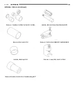
Страница 1258: ...horten the life of any tire are Rapid acceleration Severe application of brakes High speed driving Taking turns at excessive speeds Striking curbs and other obstacles Radial ply tires are more prone to irregular tread wear It is important to follow the tire rotation inter val shown in the section on Tire Rotation This will help to achieve a greater tread life potential TIRE IDENTIFICATION Tire typ...

Страница 1259: ... SPARE TIRE TEMPORARY The temporary spare tire is designed for emer gency use only The original tire should be repaired and reinstalled at the first opportunity or a new tire purchased Do not exceed speeds of 50 MPH Refer to Owner s Manual for complete details TIRE INFLATION PRESSURES Under inflation causes rapid shoulder wear tire flexing and can result in tire failure Fig 2 Over inflation causes...

Страница 1260: ...tinuous speeds above 75 mph 120 km h For emergency vehicles that are driven at speeds over 90 mph 144 km h special high speed tires must be used Consult tire manufacturer for correct inflation pressure recommendations REPLACEMENT TIRES The original equipment tires provide a proper bal ance of many characteristics such as Ride Noise Handling Durability Tread life Traction Rolling resistance Speed c...

Страница 1261: ...e will usually remain constant LEAD CORRECTION CHART Use the following chart to diagnose a vehicle that has a complaint of a drift or lead condition The use of the chart will held to determine if the lead condi tion is the result of a bad tire or is caused by the front wheel alignment Fig 5 Tire Wear Patterns CONDITION RAPID WEAR AT SHOULDERS RAPID WEAR AT CENTER CRACKED TREADS WEAR ON ONE SIDE FE...

Страница 1262: ...BE SURE TIRE PRESSURE IS EQUAL ON ALL FOUR TIRES ROAD TEST ON FLAT ROAD CAR LEADS CROSS SWITCH FRONT TIRES ROAD TEST SEE LEAD CORRECTION CHART IN THIS SECTION RECORD VEHICLE ALIGN MENT TOTAL TOE 0 2 DEGREE IN RESET ENSURING THAT STEERING WHEEL IS CEN TERED AND THE TOTAL TOE IS EQUALLY SPLIT BETWEEN EACH FRONT WHEEL CROSS CAMBER 0 4 DEGREES LOOSEN FOUR CRADLE TO BODY BOLTS SHIFT CRADLE TOWARD SIDE ...

Страница 1263: ...is maintained Refer to Owner s Manual for rotation schedule REPAIRING TIRE LEAKS For proper repairing a radial tire must be removed from the wheel Repairs should only be made if the defect or puncture is in the tread area Fig 7 The tire should be replaced if the puncture is located in the sidewall Deflate tire completely before dismounting tire from the wheel Use lubrication such as a mild soap so...

Страница 1264: ...l and Tire Runout If the high spot is NOT within 102 mm 4 0 in of either high spot draw an arrow on the tread from second high spot to first Break down the tire and remount it 90 degrees on rim in that direction Fig 10 This procedure will normally reduce the runout to an acceptable amount CLEANING AND INSPECTION CLEANING OF TIRES Remove protective coating on tires before delivery of vehicle The co...

Страница 1265: ...enger car tire or T for temporary use tire 185 Nominal width of tire in millimeters 70 Tire height to width ratio R Radial ply tire or D for bias ply tire 14 Nominal rim diameter in inches Do not install smaller than minimum size tires shown on the tire inflation placard on the vehicle 22 8 TIRES AND WHEELS JA ...

Страница 1266: ...ll aluminum and some steel wheels have wheel stud nuts with an enlarged nose This enlarged nose is necessary to ensure proper retention of the wheels Before installing a wheel remove any buildup of corrosion on the wheel mounting surface WARNING INSTALLING WHEELS WITHOUT GOOD METAL TO METAL CONTACT COULD CAUSE LOOS ENING OF WHEEL LUG NUTS THIS COULD ADVERSELY AFFECT THE SAFETY AND HANDLING OF YOUR...

Страница 1267: ...acceptable level the tire can be rotated on the wheel See Method 2 METHOD 1 RELOCATE WHEEL ON HUB Check accuracy of the wheel mounting surface adjust wheel bearings Drive vehicle a short distance to eliminate tire flat spotting from a parked position Verify all wheel nuts are properly torqued Fig 2 Use run out gauge D 128 TR to determine run out Fig 3 Relocate wheel on the mounting two studs over ...

Страница 1268: ...45 degrees from its original spot Recheck run out SERVICE PROCEDURES WHEEL INSTALLATION To install the wheel first position it properly on the mounting surface using the hub pilot as a guide All wheel nuts should then be tightened just snug Progressively tighten them in the proper sequence Fig 7 Tighten wheel nuts to 129 N m 95 ft lbs Never use oil or grease on studs or nuts Fig 5 Checking Radial ...

Страница 1269: ...ausing imbalance Counter balance wheel directly opposite the heavy spot Determine weight required to counterbalance the area of imbalance Place half of this weight on the inner rim flange and the other half on the outer rim flange Fig 8 Fig 9 Off ve hicle balancing is necessary Wheel balancing can be accomplished with either on or off vehicle equipment When using on vehicle balancing equipment rem...

Страница 1270: ...mm Mounting Stud Lug Nut Hex Size 19mm Mounting Lug Nut Tightening Torque 4 and 5 Stud Wheels 135 N m 100 ft lbs Fig 9 Dynamic Unbalance Balance OF SPINDLE ADD BALANCE WEIGHTS HERE CORRECTIVE WEIGHT LOCATION HEAVY SPOT WHEEL SHIMMY AND VIBRATION JA TIRES AND WHEELS 22 13 ...

Страница 1271: ......

Страница 1272: ...rical wiring or other compo nents Damage to vehicle can result Do not weld exterior panels unless combustible material on the interior of vehicle is removed from the repair area Fire or hazardous conditions can result Always have a fire extinguisher ready for use when welding Disconnect the negative cable clamp from the battery when servicing electrical components that are live when the ignition i...

Страница 1273: ... force pull to the panel to verify that it is secure When it is necessary to remove components to ser vice another it should not be necessary to apply excessive force or bend a component to remove it Before damaging a trim component verify hidden fasteners or captured edges holding the component in place 23 2 BODY JA GENERAL INFORMATION Continued ...

Страница 1274: ... clear coat for durability PAINTED SURFACE TOUCHUP When a painted metal surface has been scratched or chipped it should be touched up as soon as possi ble to avoid corrosion For best results use Mopart Scratch Filler Primer Touch Up Paints and Clear Top Coat Refer to Introduction group of this manual for Body Code Plate information TOUCHUP PROCEDURE 1 Scrape loose paint and corrosion from inside s...

Страница 1275: ...hite Clear Coat SW1 83542 26089 B9622 51539 CHA96 SW1 1996 MOLDING COLORS MOLDING COLOR CHRY CODE PPG BASF DUPONT S W ACME M S AKZO NOBEL SIKKENS Candy Apple Red RH2 4974 26098 B9616 51063 CHA95 RH2 5025 51064 Lt Gold SYL 83539 26097 B9618 51076 CHA96 SYL Dark Rosewood REG 4966 25041 B9519 50266 CHAREGM Orchid RMK 74085 25038 B9522 50272 CHA95 RMK Medium Fern RJP 47320 25040 B9524 50270 CHA95 RJP ...

Страница 1276: ...re the windshield to the fence is difficult to cut or clean from any surface If the moldings are set in urethane it would also be unlikely they could be salvaged Before removing the windshield check the availability of the windshield and moldings from the parts supplier REMOVAL AND INSTALLATION WINDSHIELD The urethane adhesive holding the windshield to the opening pinch weld fence can be cut using...

Страница 1277: ...indshield with ammonia based glass cleaner and lint free cloth 7 Apply molding to perimeter of windshield 8 Apply Glass Prep adhesion promoter 25 mm 1 in wide around perimeter of windshield and wipe with clean dry lint free cloth until no streaks are vis ible 9 Apply Glass Primer 25 mm 1 in wide around perimeter of windshield Allow at least three minutes drying time 10 Using a razor knife remove a...

Страница 1278: ...VAL 1 Remove rear window moldings 2 Remove upper quarter trim panel 3 Disengage wire connectors from rear window defogger and rear window mounted radio antenna if so equipped 4 Remove C pillar applique if so equipped WARNING WEAR EYE AND HAND PROTECTION WHEN HANDLING SAFETY GLASS PERSONAL INJURY CAN RESULT CAUTION Do not damage body or trim finish when cutting out glass or applying fence primer 5 ...

Страница 1279: ...rethane along centerline of window fence 5 Install the glass in the same manner described in the Windshield section of thi group Fig 7 6 Connect rear window defogger wiring and rear window mounted radio antenna if so equipped 7 Install C pillar applique and interior trim 8 After urethane has cured water test rear win dow to verify repair Verify rear window defogger operation see Group 8N Rear Wind...

Страница 1280: ...stops NOTE The sunroof will operate only when the igni tion switch is in the ON or ACC position The sun roof will not operate if the vehicle battery voltage is below 10 volts The sunroof cannot be manually operated cranked or otherwise if the sunroof becomes inoperable without a significant portion of the headlining being removed The manually operated sunshade can be positioned anywhere along its ...

Страница 1281: ...If battery voltage of more than 10 volts is detected at the controller proceed with the following tests the controller will not operate at less than 10 volts Before beginning diagnosis for wind noise or water leaks verify that the problem was not caused by releasing the control switch before the was sunroof fully closed The sunroof module has a water man agement system During washing high pressure...

Страница 1282: ... circuit ground between controller switch and body harness Faulty power circuit between controller switch and body harness Faulty sunroof drive motor Faulty sunroof controller Faulty sunroof motor connector Audible whine when switch is depressed sunroof does not operate Faulty sunroof position sensor Binding linkage Audible clicking or ratcheting when switch is pressed sunroof does not operate Bro...

Страница 1283: ...ALLATION 1 Slide sensor 18 into bracket 2 Crimp inner lip of retainer bracket 22 around sensor 3 Engage sensor wire connector 18 into sunroof controller 16 4 Bundle sensor wire 18 and install wire ties 19 5 Install headlining SUNROOF CONTROLLER REMOVAL 1 Remove headlining as necessary to gain access to sunroof controller 16 2 Disengage position sensor wire connector 18 from controller 3 Disengage ...

Страница 1284: ...y sunroof operation and alignment 10 Install mechanism reveal covers SUNROOF SUNSHADE REMOVAL 1 Remove headlining 2 Pull sunshade 6 rearward 3 Pull sunshade 6 down at front 4 Slide sunshade 6 forward through cut out in sunroof module tracks 10 CAUTION Do not crease the sunshade when removing or installing 5 Separate sunshade 6 from vehicle INSTALLATION 1 Position rear of sunshade 6 into cut out in...

Страница 1285: ...ard until it stops The panel front guide 28 MUST be to the front of the tracks on both sides to synchronize cables 9 Engage front pivot of glass lift arm 35 in hole in actuating link 34 At this time parts 27 36 35 should be attached to 37 as an assembly 10 Engage sliding roof panel cam block 37 to sunroof module track and install two screws 38 to hold it 11 Repeat above steps for other side 12 Ins...

Страница 1286: ... fore aft adjustment for the glass panel The sunroof module must be shifted during installation side to side and fore aft with the glass panel closed in order for the glass panel to center itself into the roof opening FRONT OF GLASS PANEL HEIGHT ADJUSTMENT NOTE The front corners of the sunroof glass panel 1 should be flush to 1 mm 0 04 in below the edge of roof panel CAUTION Do not use more than a...

Страница 1287: ...SPECIFICATIONS SUNROOF COMPONENTS 23 16 BODY JA ...

Страница 1288: ...s 11 Screw M6x1 0x16 6 Req d 5 5 50 37 Block Cam Roof Sliding Panel 12 Nut M6x1 00 U Type 38 Screw 8 18x 375 1 7 15 13 Bracket Rear Support 39 Washer M4 3x7x 5 14 Bracket Front Support 40 Screw M4x 7x6 1 7 15 15 Retainer M6x15 Controller 41 Washer M5 3x9x 6 16 Controller Sunroof Open Vent 42 Screw M5x 8x8 3 4 30 17 Body Harness to Sunroof 43 Washer Plastic 18 Sunroof Position Sensor 44 Dual Lock F...

Страница 1289: ...G 42 HOOD ADJUSTER BUMPER 22 HOOD HINGE 22 HOOD LATCH 21 HOOD PROP ROD 22 HOOD RELEASE CABLE 21 HOOD 21 LEFT FRONT WHEELHOUSE SPLASH SHIELD 23 LOWER B PILLAR TRIM 38 LOWER QUARTER TRIM 39 OUTER BELT MOLDING 26 PARCEL SHELF TRIM 39 QUARTER TRIM EXTENSIONS 39 RADIATOR SUPPORT CROSSMEMBER 22 REAR DOOR B PILLAR SEAL 31 REAR DOOR CHECK STRAP 34 REAR DOOR GLASS 32 REAR DOOR INNER BELT WEATHERSTRIP 31 RE...

Страница 1290: ...t turns hoist the right side of the vehi cle For hoisting recommendations refer to Group 0 Lubrication and Maintenance General Information section WATER LEAK DETECTION To detect a water leak point of entry do a water test and watch for water tracks or droplets forming on the inside of the vehicle If necessary remove inte rior trim covers or panels to gain visual access to the leak area If the hose...

Страница 1291: ...plied remove tape locate and repair defect POSSIBLE CAUSE OF WIND NOISE Moldings standing away from body surface can catch wind and whistle Gaps in sealed areas behind overhanging body flanges can cause wind rushing sounds Misaligned movable components Missing or improperly installed plugs in pillars Weld burn through holes UNIVERSAL TRANSMITTER Universal Transmitter will operate most Garage door ...

Страница 1292: ...panel behind clutch brake pedal 9 Pull release cable through hole in dash panel 10 Separate cable and handle from vehicle INSTALLATION Reverse the preceding operation HOOD REMOVAL 1 Open hood 2 Disengage under hood lamp wire connector from engine compartment wire harness 3 Mark outline of hinges on inside of hood to aid installation 4 Remove the top bolts holding hood to hinge and loosen the botto...

Страница 1293: ... panel Fig 4 INSTALLATION Reverse the preceding operation Adjust hood slam bumper to achieve a hood height that is flush across the gaps to the fenders HOOD PROP ROD REMOVAL 1 Release hood latch and open hood CAUTION Do not place prop rod or substitute against outer hood panel damage to exterior finish will result 2 Using a length of wooden dowel rod prop hood open 3 Disengage prop rod from retain...

Страница 1294: ... tightening pro cedures 3 Remove battery splash shield 4 Remove screws holding wheelhouse splash shield to front fender lip Fig 7 5 Remove push in fastener holding wheelhouse splash shield to fender at the rocker panel 6 Remove push in fasteners holding wheelhouse splash shield to fender support 7 Separate wheelhouse splash shield from vehi cle INSTALLATION Reverse the preceding operation ACCESSOR...

Страница 1295: ...l cup to sup port bracket behind trim panel 7 Remove screw cap from behind inside door latch handle 8 Remove screw holding door latch handle to door panel 9 Disengage clips holding trim panel to perimeter of door 10 Lift trim panel upward to disengage upper retainer channel 11 Tilt top of trim panel away from door 12 Disengage clip holding latch linkage to back of release handle Fig 11 13 Separate...

Страница 1296: ...g secondary sill weatherstrip to bottom of door 3 Separate secondary sill weatherstrip from vehi cle Fig 13 INSTALLATION Reverse the preceding operation FRONT DOOR GLASS REMOVAL 1 Remove door trim panel and inner belt weath erstrip 2 Connect power window switch or install crank and lower window to 50 mm 2 in from bottom of travel 3 Loosen screws holding regulator roller channel to glass 4 Slide ro...

Страница 1297: ...l 4 Position screw and bolt heads in keyhole slots in door panel 5 Tighten screw holding regulator scissor channel to door panel 6 Engage power window motor wire connector if equipped 7 Position glass in regulator roller channel 8 Tighten fasteners holding door glass to roller channel 9 Install door trim panel OUTER BELT MOLDING REMOVAL 1 Remove screw holding rearward end of molding to front door ...

Страница 1298: ...ed loosen set screw holding cable adjuster to side view mirror bezel 5 Separate cable adjuster from side view mirror bezel INSTALLATION Reverse the preceding operation SIDE VIEW MIRROR REMOVAL 1 Remove side view mirror bezel 2 Disengage power mirror wire connector from door harness if so equipped 3 Disengage push in fastener holding power mir ror wire lead to inner door panel 4 Remove nuts holding...

Страница 1299: ...REMOVAL 1 Remove front door outside handle 2 Disengage clip holding lock linkage to back of lock cylinder 3 Separate linkage from lock cylinder 4 Remove retainer holding lock cylinder to outer door panel Fig 23 5 Separate lock cylinder from vehicle INSTALLATION Reverse the preceding operation FRONT DOOR CHECK STRAP REMOVAL 1 Remove front door trim panel 2 Remove bolt holding check strap to hinge p...

Страница 1300: ...ine of door latch striker on B pillar to aid installation 2 Remove screws holding door latch striker to B pillar Fig 26 3 Separate door latch striker from vehicle NOTE Be sure to check for any shims between door latch striker and B pillar If any shims are found they must be re installed with the new door latch striker to maintain proper door operation INSTALLATION Reverse the preceding operation D...

Страница 1301: ...l cup 4 Remove screw from bottom of arm rest pull cup Fig 30 5 Remove screw cap from behind door latch han dle 6 Remove screw holding door latch handle to door 7 Disengage clips holding perimeter of trim panel to rear door 8 Disengage trim panel from inner belt weather strip at top of door 9 Separate top of trim panel from door 10 Disengage clip holding linkage to latch handle Fig 31 11 Separate l...

Страница 1302: ...ehicle Fig 32 INSTALLATION Reverse the preceding operation SECONDARY REAR SILL WEATHERSTRIP REMOVAL 1 Open rear door 2 Using fork tool C 4828 disengage push in fas teners holding secondary sill weatherstrip to bottom of door 3 Separate secondary rear sill weatherstrip from vehicle Fig 33 INSTALLATION Reverse the preceding operation REAR DOOR B PILLAR SEAL REMOVAL 1 Using a suitable heat gun warm s...

Страница 1303: ...nel to inner door panel 7 Install door trim panel and inner belt weather strip REAR DOOR WINDOW REGULATOR Power and manual door glass regulators are ser viced using the same procedures For power window motor service procedures refer to Group 8S Power Windows REMOVAL 1 Remove door trim panel 2 Separate glass from regulator roller channel 3 Disengage power window motor wire connector if equipped 4 L...

Страница 1304: ...REAR DOOR LATCH REMOVAL 1 Remove rear door trim panel 2 Close door glass 3 Remove lower rear run channel 4 Disengage clips holding linkage rods to door latch 5 Separate linkage rods from latch Fig 40 6 Remove screws holding latch to door end frame 7 Separate latch from door INSTALLATION CAUTION Do not close door before adjusting the door latch door may fail to open Reverse the preceding operation ...

Страница 1305: ...REAR DOOR REMOVAL 1 Open and support door on a suitable lifting device 2 Disengage wire connector at hinge pillar 3 Remove bolts holding door check strap to B pil lar 4 Remove clip holding hinge pin in lower door hinge Fig 43 5 Remove pin from lower hinge 6 Remove clip holding hinge pin in upper hinge 7 Remove pin from upper hinge 8 Separate door from vehicle INSTALLATION Reverse the preceding ope...

Страница 1306: ...nt IP console 6 Separate floor console from vehicle INSTALLATION Reverse the preceding operation FORWARD IP CONSOLE REMOVAL 1 Remove floor console 2 Remove instrument cluster bezel refer to Group 8E Instrument Panel and Gauges for proper procedure 3 Remove screws holding storage bin forward IP console Fig 46 4 Separate storage bin from console 5 Remove screws holding forward IP console to gear sel...

Страница 1307: ...rate seat back from vehicle INSTALLATION 1 Position seat back in vehicle 2 Push seat back downward to engage hooks holding seat back to trunk closure panel 3 Install bolts holding seat back to parcel shelf mount bracket 4 Install bolts holding seat back and seat belts to floor pan 5 Install rear seat cushion Fig 46 Floor Console INSTRUMENT PANEL FORWARD IP CONSOLE AUTO TRANS KNOB SET SCREW STORAGE...

Страница 1308: ...e seat back from vehicle INSTALLATION 1 Position seat back in vehicle 2 Engage folding rear seat back latch 3 Install pivot bolts holding folding rear seat back to lower pivot brackets 4 Install side bolsters 5 Install rear seat cushion FOLDING REAR SEAT BACK LATCH HANDLE REMOVAL 1 From inside luggage compartment disengage push in retainer holding latch release handle to bot tom of parcel shelf 2 ...

Страница 1309: ...ar trim to B pillar 6 Separate upper B pillar trim from vehicle Fig 51 INSTALLATION Reverse the preceding operation LOWER B PILLAR TRIM REMOVAL 1 Remove upper B pillar trim 2 Disengage clips holding seat belt access panel to lower B pillar trim Fig 51 3 Remove sill plates 4 Disengage clips holding lower B pillar trim to B pillar 5 Route seat belt webbing through access hole in lower B pillar trim ...

Страница 1310: ...eration QUARTER TRIM EXTENSIONS REMOVAL 1 Remove rear seat back side bolsters 2 Disengage clips holding quarter trim exten sions to trunk closure panel Fig 52 3 Separate quarter trim extensions from vehicle INSTALLATION Reverse the preceding operation PARCEL SHELF TRIM REMOVAL 1 Remove upper quarter trim panels 2 Remove rear seat cushion and back or quarter extension panels 3 Remove push in fasten...

Страница 1311: ...ig 51 Interior Trim Panels A PILLAR TRIM ACCESS PANEL SILL PLATE RETAINERS COWL TRIM UPPER B PILLAR TRIM SILL PLATE LOWER B PILLAR TRIM SILL PLATE SEAT BELT UPPER QUARTER TRIM LOWER QUARTER TRIM Fig 52 Quarter Trim Extensions RIGHT QUARTER TRIM EXTENSION LEFT QUARTER TRIM EXTENSION TRUNK CLOSURE PANEL FWD Fig 53 Parcel Shelf Trim Panel PUSH IN FASTENER TRUNK CLOSURE PANEL CLIP PARCEL SHELF TRIM RE...

Страница 1312: ...ower B pillar trim panels as necessary to clear carpet 6 Remove cowl trim panels 7 Remove floor console 8 Remove forward IP console 9 Disengage retainer channels holding carpet to door sills Fig 56 10 Pull carpet from behind brake pedal acceler ator pedal and HEVAC 11 Fold carpet to center of vehicle 12 Remove carpet from vehicle through passen ger door opening INSTALLATION Reverse the preceding o...

Страница 1313: ... if so equipped 9 Pull sunroof switch if so equipped straight down to disengage switch from retainer 10 Disengage wire connector from sunroof switch if so equipped 11 Remove left A pillar trim panel 12 Disengage push in fasteners holding head liner wiring harness to A pillar and instrument panel brackets 13 Disengage headliner wire connector from fuse panel Fig 58 14 Disengage upper fasteners on r...

Страница 1314: ...ss to A pillar and fuse panel NOTE It is not possible to re install the push in fasteners holding the wiring harness to the instru ment panel bracket and to the fuse panel area Wrap these two fasteners with foam tape to prevent buzz squeak and rattle complaints Fig 58 19 Install A pillar trim panels 20 Install B pillar trim panels 21 Install upper quarter trim panels 22 Verify that the door openin...

Страница 1315: ...side of trunk lid to aid installation Fig 61 3 Place a padded block between the deck panel and the trunk lid 4 Remove bolts holding hinge to trunk lid 5 Place trunk lid against padded block and hold it steady 6 Remove bolts holding hinge to quarter panel trough 7 Separate hinge from vehicle INSTALLATION Reverse the preceding operation TRUNK LATCH REMOVAL 1 Open trunk lid 2 Disengage clips holding ...

Страница 1316: ...ired to maintain ease of operation and to provide protection against rust and wear When performing other underhood services the hood latch release mecha nism and safety catch should be inspected cleaned and lubricated During the winter season external door lock cylinders should be lubricated to assure proper operation when exposed to water and ice Prior to the application of any lubricant the part...

Страница 1317: ...atch MOPART MULTI PURPOSE GREASE OR EQUIVALENT All Other Hood Mechanisms MOPART LOCK CYLINDER LUBRICANT OR EQUIVALENT Door Lock Cylinders Trunk Lock Cylinder Fig 64 Trunk Release Cable and Latch Striker TRUNK LATCH STRIKER LATCH RELEASE CABLE QUARTER PANEL B PILLAR TRUNK RELEASE HANDLE Fig 65 Door Latch Adjustment DOOR HAN DLE LATCH ADJUST MENT ACCESS HOLE HEX WRENCH 23 46 BODY JA SPECIFICATIONS C...

Страница 1318: ...SPECIAL TOOLS BODY REMOVER MOLDINGS C 4829 STICK TRIM C4755 JA BODY 23 47 ...

Страница 1319: ......

Страница 1320: ...onsole from vehicle INSTALLATION Reverse the preceding operation FORWARD IP CONSOLE REMOVAL 1 Remove floor console 2 Remove instrument cluster bezel refer to Group 8E Instrument Panel and Gauges for proper procedure 3 Remove screws holding storage bin forward IP console Fig 1 4 Separate storage bin from console 5 Remove screws holding forward IP console to gear selector mount bracket 6 Remove scre...

Страница 1321: ...Fig 1 Floor Console 23 2 BODY JA REMOVAL AND INSTALLATION Continued ...

Страница 1322: ... WHEEL ASSEMBLY 13 BLOWER MOTOR RESISTOR 13 BLOWER MOTOR WHEEL 14 COMPRESSOR CLUTCH COIL ASSEMBLY 15 COMPRESSOR 14 CONDENSER 17 CONTROL MODULE 17 DISCHARGE LINE 18 EVAPORATOR PROBE 20 EVAPORATOR 19 EXPANSION VALVE 21 FILTER DRIER 22 HEATER CORE 23 HEATER HOSES 24 LIQUID LINE 25 MODE DOOR ACTUATOR MOTOR 12 RECIRCULATION DOOR CABLE 26 SUCTION LINE 28 TEMPERATURE DOOR CABLE 28 THERMAL LIMITER SWITCH ...

Страница 1323: ...ER The switch is located on the discharge line near the compressor The pressure transducer functions as the refrigerant system pressure sensor It supports the condenser radiator fans and compressor func tions CLUTCH PULLEY AND COIL They are mounted on the compressor providing a way to drive the compressor The compressor clutch and coil are the only serviced parts on the compres sor When the compre...

Страница 1324: ...ng all refrigerant from the air conditioning system The system must be empty All quick connects use two O rings to seal the con nection The O rings are made from a special type of rubber that is not affected by R 134a refrigerant O ring replacement is required whenever lines are removed and installed Use only O rings specified for this vehicle Failure to use the correct type of O ring will cause t...

Страница 1325: ...by debris in the refrigerant system If debris is believed to be the cause recycle the refrigerant and replace the expansion valve and receiver drier HANDLING TUBING AND FITTINGS Kinks in the refrigerant tubing or sharp bends in the refrigerant hose lines will greatly reduce the capacity of the entire system High pressures are pro duced in the system when it is operating Extreme care must be exerci...

Страница 1326: ...ting verify that the valve of the coupling is fully closed This will reduce the amount of effort required to make the connection 1 Connect a tachometer and manifold gauge set Attach a thermal couple to the evaporator line 2 Set control to A C RECIRC and PANEL tem perature lever on full cool and blower on high 3 Start engine and hold at 1000 rpm with A C clutch engaged 4 Engine should be warmed up ...

Страница 1327: ...ithin the specifications shown If not OK replace the control module If OK check Blown fuse Cut wire Poor ground Poor connection Defective BCM Bulkhead connector inoperative Refer to Group 8W Wiring Diagrams HEATER PERFORMANCE TEST PRE DIAGNOSTIC PREPARATIONS Review Safety Precautions and Warnings in this group before performing the following procedures Check the coolant level drive belt tension va...

Страница 1328: ...omponents The evaporator condenser and receiver drier will retain a significant amount of oil Refer to the A C Component Refrigerant Oil Capaci ties chart below When a component is replaced the specified amount of refrigerant oil must be added When the compressor is replaced the amount of oil that is retained in the rest of the system must be drained from the replacement compressor When a line or ...

Страница 1329: ...mixed with the refrig erant will raise the compressor head pressure above acceptable operating levels This will reduce the per formance of the air conditioner and damage the com pressor Moisture will boil at near room temperature when exposed to vacuum To evacuate the refrigerant system NOTE When connecting the service equipment coupling to the line fitting verify that the valve of the coupling is...

Страница 1330: ...ant charge levels Fig 7 Due to the different characteristics of R 134a it requires all new service procedures WARNING AVOID BREATHING A C REFRIGERANT AND LUBRICANT VAPOR OR MIST EXPOSURE MAY IRRITATE EYES NOSE AND THROAT USE ONLY APPROVED SERVICE EQUIPMENT MEETING SAE REQUIREMENTS TO RECLAIM R 134a SYSTEMS IF ACCIDENTAL SYSTEM DISCHARGE OCCURS VEN TILATE WORK AREA BEFORE RESUMING SER VICE R 134a S...

Страница 1331: ...compressor discharge pressure Use a manifold gauge set or a scan tool 2 Attach a clamp on thermocouple P S E 66 324 0014 or 80PK 1A or equivalent to the liquid line It must be placed as close to the condenser outlet as possible to observe liquid line temperature Refer to Thermocouple Probe in this section for more infor mation on probe 3 The vehicle must be in the following modes Transaxle in Park...

Страница 1332: ... review of the fittings lines and components for oily residue is an indication of the leak location To detect a leak in the refrigerant system perform one of the following procedures as indicated by the symptoms EMPTY REFRIGERANT SYSTEM LEAK TEST 1 Evacuate the refrigerant system to the lowest degree of vacuum possible approx 28 in Hg Deter mine if the system holds a vacuum for 15 minutes If vacuu...

Страница 1333: ...er is available through the Professional Service Equipment program It can convert any standard digital multimeter into a ther mometer This adapter is designed to accept any standard K type thermocouple If a digital multimeter is not available it to can be ordered through Professional Service Equipment pro gram REMOVAL AND INSTALLATION MODE DOOR ACTUATOR MOTOR NOTE If battery voltage is low or not ...

Страница 1334: ...m 50 in lbs BLOWER MOTOR AND WHEEL ASSEMBLY The blower motor is located on the right side of the heater housing REMOVAL 1 Disconnect battery 2 Remove lower right under panel silencer duct 3 Remove blower motor connector from resistor block Fig 13 4 Remove blower motor case retaining screws 5 Lower blower motor case from housing Fig 14 6 Remove fan scroll from motor shaft 7 Remove motor from motor ...

Страница 1335: ...d remove drive belt Fig 16 Refer to Group 7 Engine Cooling 3 Disconnect compressor clutch wire lead 4 Recover refrigerant system with R 134a recov ery unit 5 Remove refrigerant lines from compressor Fig 17 6 Remove compressor attaching bolts Fig 18 and Fig 19 7 Remove compressor Fig 20 Fig 13 Blower Motor Wiring BLOWER MOTOR BLOWER MOTOR WIRING Fig 14 Blower Motor BLOWERMOTOR Fig 15 Blower Motor R...

Страница 1336: ...late assembly and rotor pulley to remove the armature plate This may damage the armature plate assembly 4 Remove pulley retaining snap ring with snap ring pliers Remove pulley assembly from compressor Use a plastic hammer if necessary 5 Loosen the lead wire retaining clamps and remove lead wire from the compressor front end cover Disconnect the lead wire from the thermal lim iter switch 6 Remove s...

Страница 1337: ... CAUTION If snap rings on field coil or pulley assembly are not fully seated they will vibrate out A clutch failure and possible severe damage to the compressor could result 4 Position pulley assembly onto compressor CAUTION Do not mar the pulley frictional surface 5 Install pulley assembly retaining snap ring bevel side outward with snap ring pliers Insure snap ring is properly seated into groove...

Страница 1338: ...COMBUSTIBLE AT ELEVATED PRESSURES THESE MIXTURES ARE POTENTIALLY DANGER OUS AND MAY RESULT IN FIRE OR EXPLOSION CAUSING INJURY OR PROPERTY DAMAGE REMOVAL 1 Remove refrigerant from the A C system using a refrigerant recovery machine 2 Disconnect and cap A C lines at the condenser 3 Remove grille retainers Fig 25 Refer to Group 23 Body for removal procedures 4 Remove upper radiator support crossmemb...

Страница 1339: ...justed and the module is seated properly CABLE ADJUSTMENT The cables must be adjusted for proper function of the control module To adjust the cable attach the cable to the lever arm of the control module Turn the knob fully counterclockwise Pull the cable jacket away from the cable end until taut Clip the cable jacket to the control module The knob should travel a full 180 if the cable is properly...

Страница 1340: ... for procedure 3 Remove recirculation door inlet cover 4 Remove evaporator temperature probe 5 Remove clips retaining evaporator housing to heater distribution housing Fig 36 6 Separate evaporator housing from heater distri bution housing Fig 37 and Fig 38 7 Remove seal around evaporator tube inlet 8 Remove evaporator housing upper cover Fig 39 9 Lift evaporator out of lower housing Fig 40 10 Remo...

Страница 1341: ...sing Clips HOUSING CLIPS Fig 37 Separate Housings HEATER HOUS ING EVAPORATOR HOUSING Fig 38 Housings EVAPORATOR HOUSING HEATER DISTRIBUTION HOUSING Fig 39 Evaporator Housing Upper Cover EVAPORATOR HOUSING COVER EVAPORATOR HOUSING Fig 40 Remove Evaporator From Housing EVAPORATOR Fig 41 Evaporator Probe Wiring PROBE CONNECTOR EVAPORATOR PROBE 24 20 HEATING AND AIR CONDITIONING JA REMOVAL AND INSTALL...

Страница 1342: ...T EXPOSURE MAY IRRITATE EYES NOSE AND THROAT USE ONLY APPROVED SERVICE EQUIPMENT MEETING SAE REQUIREMENTS TO DISCHARGE R 134a SYSTEM IF ACCIDENTAL SYSTEM DISCHARGE OCCURS VENTILATE WORK AREA BEFORE RESUMING SER VICE R 134a SERVICE EQUIPMENT OR VEHICLE A C SYSTEM SHOULD NOT BE PRESSURE TESTED OR LEAK TESTED WITH COMPRESSED AIR SOME MIXTURES OF AIR R 134a HAVE BEEN SHOWN TO BE COMBUSTIBLE AT ELEVATE...

Страница 1343: ...also has a desiccant bag and a filter This is used to absorb moisture and filter the refrigerant as it passes through the filter drier The filter drier is located left of the coolant bottle Fig 51 The A C refrigerant must be removed from the system before removing the filter drier Always use a refrigerant recovery machine Fig 46 Special Tool 7240 For Liquid Line SPECIAL TOOL OTC 7240 LIQUID LINE F...

Страница 1344: ...de the vehicle However if the core has leaked a significant amount of coolant the A C housing must be removed The housing should be disassembled and cleaned thor oughly before heater core replacement If housing removal is necessary refer to Heater A C Housing Removal and Installation in this section REMOVAL 1 Disconnect battery negative remote cable 2 Remove radio control module bezel Fig 29 3 Rem...

Страница 1345: ...s remove clamps at each end of hose to be removed Fig 55 and Fig 56 3 Carefully rotate hose back and forth while tug ging slightly away from connector nipple CAUTION When removing hoses from heater core inlet or outlet nipples do not use excessive force Heater core may become damaged and leak engine coolant into heater unit INSTALLATION For installation reverse the above procedures HEATER HOSES 2 ...

Страница 1346: ...pansion valve Remove liquid line from expansion valve Use Special Tool kit 7193 to disconnect quick connector Fig 59 CAUTION Cap all lines that are not being replaced and cap the expansion valve tubes 4 Disconnect liquid line from the receiver drier Fig 60 5 Remove the liquid line from the vehicle INSTALLATION For installation reverse the above procedu8res Fig 57 Heater Hose Connection At Engine H...

Страница 1347: ...ht of the A C Heater housing near the right A pil lar Fig 65 REMOVAL 1 Place the ignition key in the OFF position before removing control module 2 Remove trim bezel Fig 66 3 Remove cluster hood bezel retaining screws in the trim bezel opening Fig 67 4 Pry up the cluster hood bezel a few inches to expose the cubby bin cigar lighter bezel screws 5 Remove the cubby bin cigar lighter bezel and wiring ...

Страница 1348: ...g Fig 69 11 Remove cable core end from recirculation actuator lever Fig 65 Recirculation Cable Location TEMPERATURE DOOR CABLE CONTROL MODULE A C HOUSING RECIRCULATION DOOR CABLE Fig 66 Trim Bezel TRIM BEZEL Fig 67 Control Module Screws CONTROL MODULE SCREWS CLUSTER HOOD SCREWS Fig 68 Control Module At Bezel Opening CONTROL MODULE Fig 69 Disconnect Recirculation Cable RECIRCULATION CABLE JA HEATIN...

Страница 1349: ...ubes 4 Disconnect line at compressor end Fig 72 5 Remove suction line from vehicle INSTALLATION For installation reverse the above procedures Tighten bolts to 22 N m 200 in lbs TEMPERATURE DOOR CABLE The blend air temperature door is actuated by a cable which mechanically positions the temperature door The temperature door actuator is located at the center of the A C Heater housing at the center t...

Страница 1350: ...ions at the bulk head Refer to group 11 Exhaust System And Intake Manifold for service information 5 Disconnect heater hoses at the dash panel Plug the heater core inlet and outlet tubes to prevent antifreeze from spilling on the vehicle interior during removal If an appropriate plug cannot be found pull back carpet and use caution when removing unit Keep the heater tubes elevated to prevent spill...

Страница 1351: ...ble jacket away from the cable end until taut Clip the cable jacket to the control module The knob should travel a full 180 if the cable is properly adjusted DISASSEMBLY AND ASSEMBLY UNIT HOUSING RECONDITION Heater A C housing must be removed from vehicle before performing this operation Refer to Heater A C Unit Housing Removal and Installation The heater a c unit need not be disassembled to repla...

Страница 1352: ...er Motor Wiring BLOWER MOTOR BLOWER MOTOR WIRING Fig 78 Recirculation Housing Removal RECIRCULATION HOUSING Fig 79 Rear Y Cam Release Y CAM ACTUATOR LEVER REAR DOOR FLAT BLADE PRY TOOL Fig 80 Rear Y Cam Actuator REAR Y CAM ACTUATOR LEVER REAR LEVER AIR INLET FRONT TOGGLE LEVER FRONT ACTUATOR LEVER Fig 81 Rear Air Inlet Door RECIRC HOUSING REAR DOOR REAR Y CAM ACTUATOR LEVER FRONT TOGGLE LEVER REAR...

Страница 1353: ...orator Fig 85 16 Remove blower motor resistor Fig 86 17 Remove clips retaining evaporator housing to heater distribution housing Fig 87 Fig 83 Blower Motor BLOWERMOTOR Fig 84 Evaporator Probe EVAPORATOR PROBE Fig 85 Evaporator Probe Needle EVAPORATOR PROBE NEE DLE Fig 86 Blower Motor Resistor BLOWER RESISTOR Fig 87 Housing Clips MOUNTING CLIPS 24 32 HEATING AND AIR CONDITIONING JA DISASSEMBLY AND ...

Страница 1354: ...ew Fig 96 27 Remove temperature door lever link Fig 97 28 From the panel door air opening using a long thin screwdriver push in clip for floor door gear Remove floor door gear Fig 98 29 Turn floor door lever link until it aligns with slots cut into it Fig 99 Remove floor door lever link Fig 100 Fig 88 Separate Housings HEATER DISTRIBUTION HOUSING A C EVAPORATOR HOUSING Fig 89 Evaporator Tube Inlet...

Страница 1355: ...anel door gear from housing Fig 93 Heater Core Cover Fig 94 Heater Core Cover Removal HEATER CORE COVER Fig 95 Slide Out Core HEATER CORE Fig 96 Temperature Door Lever Link Fig 97 Temperature Door Lever Link Removal TEMPERATURE DOOR LEVER LINK Fig 98 Floor Door Gear FLAT BLADE PRY TOOL FLOOR DOOR GEAR 24 34 HEATING AND AIR CONDITIONING JA DISASSEMBLY AND ASSEMBLY Continued ...

Страница 1356: ...st door from housing Fig 107 Fig 99 Align Slots LINE UP SLOTS FLOOR DOOR LEVER LINK Fig 100 Remove Lever Link FLOOR DOOR LEVER Fig 101 Mode Motor Cam DEFROST DOOR LEVER LINK PANEL DOOR LEVER PANEL DOOR LEVER LINK MODE CAM DEFROST DOOR LEVER Fig 102 Mode Motor Cam Removal MODE CAM Fig 103 Panel Door Gear Release FLAT BLADE PRY TOOL PANEL DOOR Fig 104 Panel Door Lever Link PANEL DOOR LEVER LINK JA H...

Страница 1357: ...motor cam 7 Install floor door lever link 8 Install floor door lever gear 9 Install temperature door lever gear 10 Install temperature door lever link 11 Slide heater core into housing Install cover 12 Install lower distribution housing and clips 13 Install styrofoam to evaporator Install evapo rator into the evaporator housing 14 Install upper cover to evaporator housing 15 Install seal around ev...

Страница 1358: ...4A Oil SP15PAG 150cc 5 08 fl oz Weight 39 2 N m 8 82 lbs 4 0 kgf CLUTCH DESCRIPTION Rated Voltage 12 VDC Minimum Breakaway Torque 31 4 N m 23 ft lbs 3 2 Kgf m at 12VDC Minimum Engagement Voltage 7 5 AT AIR GAP 0 5 mm REF Power Consumption 50 WATTS MAX Pulley Diameter 110 mm DIA 4 3 in Weight 18 9 N m 4 23 lbs 1 92 Kgf Clutch Type Standard THERMAL LIMITER SWITCH DESCRIPTION TEMPERATURE Cut OFF Temp...

Страница 1359: ......

Страница 1360: ...of engine RPM engine temperature and or input voltage to the PCM The PCM might not store a DTC for a monitored circuit even though a malfunction has occurred This may happen because one of the DTC criteria for the circuit has not been met For example assume the diagnostic trouble code criteria requires the PCM to monitor the circuit only when the engine operates between 750 and 2000 RPM Suppose th...

Страница 1361: ...ize The PCM attempts to activate these outputs and allow an observer to verify proper operation Most of the tests provide an audible or visual indication of device operation click of relay contacts fuel spray etc Except for intermittent conditions if a device functions properly during testing assume the device its associated wiring and driver circuit work cor rectly DIAGNOSTIC TROUBLE CODES A Diag...

Страница 1362: ...ve test of generator output circuit 06 46 Charging System Voltage Too High Battery voltage sense input above target charging voltage during engine operation 0A 42 Auto Shutdown Relay Control Circuit An open or shorted condition detected in the auto shutdown relay circuit 0B 41 Generator Field Not Switching Properly An open or shorted condition detected in the generator field control circuit 0F 34 ...

Страница 1363: ...on Coil 1 Primary Circuit Peak primary circuit current not achieved with maximum dwell time 2C 42 No ASD Relay Output Voltage at PCM An Open condition Detected In The ASD Relay Output Circuit 2E 32 P0401 EGR System Failure Required change in air fuel ratio not detected during diagnostic test 30 62 P1697 PCM Failure SRI Miles Not Stored Unsuccessful attempt to update EMR mileage in the PCM EEPROM 3...

Страница 1364: ... from Transmission Control Module or 61 P1695 No CCD Message From Body Control Module No messages received from Body Control Module 65 42 Fuel Pump Relay Control Circuit An open or shorted condition detected in the fuel pump relay control circuit 66 21 P0133 Right Bank Upstream O2S Slow Response Oxygen sensor response slower than minimum required switching frequency or 67 P0135 Right Rear or just ...

Страница 1365: ...P1294 Target Idle Not Reached Actual idle speed does not equal target idle speed 91 25 P1299 Vacuum Leak Found IAC Fully Seated MAP sensor signal does not correlate to throttle position sensor signal Possible vacuum leak 92 71 P1496 5 Volt Supply Output Too Low 5 volt output from regulator does not meet minimum requirement 95 42 Fuel Level Sending Unit Volts Too Low Open circuit between PCM and fu...

Страница 1366: ...ion and emission systems monitors do not indicate a specific component prob lem They do indicate that there is an implied prob lem within one of the systems and that a specific problem must be diagnosed If any of these monitors detect a problem affecting vehicle emissions the Malfunction Indicator Check Engine Lamp will be illuminated These monitors generate Diagnostic Trouble Codes that can be di...

Страница 1367: ... engine driving conditions When the conditions are met the EGR is turned off solenoid energized and the O2S compensation control is mon itored Turning off the EGR shifts the air fuel A F ratio in the lean direction The O2S data should indi cate an increase in the O2 concentration in the com bustion chamber when the exhaust gases are no longer recirculated While this test does not directly measure ...

Страница 1368: ... valve CVV seal which contains a spring loaded vent seal valve Immediately after a cold start between predeter mined temperature thresholds limits the three port solenoid is briefly energized This initializes the pump by drawing air into the pump cavity and also closes the vent seal During non test conditions the vent seal is held open by the pump diaphragm assembly which pushes it open at the ful...

Страница 1369: ...osition sensor TPS was checked by the PCM for an open or shorted circuit If one of these conditions occurred a DTC was set Now there is a check to ensure that the component is working This is done by watching for a TPS indication of a greater or lesser throttle opening than MAP and engine rpm indicate In the case of the TPS if engine vacuum is high and engine rpm is 1600 or greater and the TPS ind...

Страница 1370: ...mod ule should be mounted to the body at all times also during diagnostic PCM CONNECTOR ENGAGEMENT The PCM may not be able to determine spread or damaged connector pins However it might store diagnostic trouble codes as a result of spread connec tor pins HIGH AND LOW LIMITS The PCM compares input signal voltages from each input device with established high and low limits for the device If the inpu...

Страница 1371: ...hicle rollover All vehicles pass a 360 rollover The pressure relief valve opens at a certain pres sure When fuel tank pressure increases above the calibrated pressure the valve opens to release fuel tank vapors pressure The charcoal filled evaporative canister stores the vapors For pressure relief rollover valve service refer to the Fuel Tank section of Group 14 EVAP CANISTER All vehicles use a se...

Страница 1372: ...ed and relieves fuel tank pres sure If the filler cap needs replacement only use the correct part POSITIVE CRANKCASE VENTILATION PCV SYSTEMS Intake manifold vacuum removes crankcase vapors and piston blow by from the engine The emissions pass through the PCV valve into the intake manifold where they become part of the calibrated air fuel mixture They are burned and expelled with the exhaust gases ...

Страница 1373: ...back from the inlet This results in maximum vapor flow through the valve Fig 9 VEHICLE EMISSION CONTROL INFORMATION LABEL All models have a Vehicle Emission Control Infor mation VECI Label Chrysler permanently attaches the label in the engine compartment It cannot be removed without defacing information and destroying the label The label contains the vehicle s emission specifica tions and vacuum h...

Страница 1374: ...l be heard and a strong vacuum felt when placing a finger over the valve inlet Fig 10 With the engine off shake the valve The valve should rattle when shaken Replace the valve if it does not operate properly Do not attempt to clean the PCV valve VACUUM SCHEMATIC If any difference exists between the diagram on the Vehicle Emission Control Information VECI label and this illustration refer to the la...

Страница 1375: ...ENGINE VACUUM SCHEMATIC 2 0L 25 16 EMISSION CONTROL SYSTEMS JA DIAGNOSIS AND TESTING Continued ...

Страница 1376: ...ENGINE VACUUM SCHEMATIC 2 4LATX JA EMISSION CONTROL SYSTEMS 25 17 DIAGNOSIS AND TESTING Continued ...

Страница 1377: ...ENGINE VACUUM SCHEMATIC 2 5LATX 25 18 EMISSION CONTROL SYSTEMS JA DIAGNOSIS AND TESTING Continued ...

Страница 1378: ...cle 5 Disconnect vacuum line from Leak Detection Pump LDP 6 Remove hoses from evaporative canister 7 Remove 3 nuts retaining evaporative canister to pump bracket Fig 11 Headlamp Attachment HEADLAMP ATTACHING BOLTS Fig 12 Headlamp Electrical Connector Removal Installation HEADLAMP ASSEMBLY Fig 13 Vacuum Line On LDP SERVICE VAC UUM SUPPLY LEAK DETECTION PUMP Fig 14 Evaporative Canister Attachment Nu...

Страница 1379: ...d tighten 2 screws 7 Use the DRB to test the LDP and system ROLLOVER VALVES All vehicles have 2 rollover valves on top of the fuel tank The valves prevent fuel flow through the fuel tank vent valve hoses should the vehicle rollover The rollover valves on the fuel tank are not ser viceable Fig 15 LDP Bracket Mounting Holes LDP BRACKET MOUNTING HOLES Fig 16 Front Upper Mounting Bolt FRONT UPPER MOUN...

Страница 1380: ... nitrogen NOx in engine exhaust and helps prevent detonation engine knock Under normal operating conditions engine cylinder temperature can reach more than 3000 F Formation of NOx increases proportionally with combustion temperature To reduce the emission of these oxides the cylinder temperature must be lowered The system allows a predetermined amount of hot exhaust gas to recirculate and dilute t...

Страница 1381: ...talling and increased emissions DIAGNOSIS AND TESTING EGR SYSTEM ON BOARD DIAGNOSTICS The PCM performs an on board diagnostic check of the EGR system The diagnostic system uses the electronic EGR transducer for the system tests The diagnostic check activates only during selected engine driving conditions When the conditions are met the PCM energizes the transducer solenoid to disable the EGR The P...

Страница 1382: ...es are equipped with two fittings located on the EGR valve Fig 6 The upper fitting located on the vacuum motor supplies engine vac uum to a diaphragm within the EGR valve for valve operation The lower fitting located on the base of the EGR valve is used to supply exhaust back pres sure to the EGR valve control 2 Disconnect the rubber hose at the vacuum motor fitting Fig 6 on the top of the EGR val...

Страница 1383: ...r cleaner housing from the throt tle body 5 Using compressed air and using an air nozzle with a rubber tip apply approximately 50 psi of reg ulated shop air to the metal back pressure fitting on the EGR valve 6 By hand open the throttle to the wide open position Air SHOULD NOT BE HEARD emitting from the intake manifold while applying air pressure at the back pressure fitting 7 If air CAN BE HEARD ...

Страница 1384: ...ectly replace the entire EGR valve and transducer together The EGR valve and electrical transducer are calibrated together REMOVAL The EGR valve and EGR transducer attach to the rear of the cylinder head Fig 7 1 Disconnect vacuum supply tube from EGR transducer solenoid 2 Disconnect electrical connector from solenoid 3 Remove EGR tube to EGR valve screws 4 Remove EGR valve mounting screws Remove E...

Страница 1385: ...d 7 Attach electrical connector to solenoid EGR TUBE 2 0L The EGR tube attaches to the intake manifold ple num below the throttle body and EGR valve REMOVAL 1 Remove screws attaching EGR tube to intake manifold Fig 10 2 Remove EGR tube to EGR valve screws 3 Remove EGR tube Clean gasket surface on the EGR valve Wipe clean the grommet on the intake manifold INSTALLATION The rubber grommet that seals...

Страница 1386: ... EGR valve REMOVAL 1 Remove screws attaching EGR tube to intake manifold Fig 12 2 Remove EGR tube to EGR valve screws Fig 13 3 Remove EGR tube Clean gasket surface on the EGR valve Wipe clean the grommet on the intake manifold INSTALLATION Use new gaskets on both ends of the EGR tube 1 Loosely install the EGR tube and fasteners 2 Tighten the EGR tube to intake manifold ple num screws to 11 N m 95 ...

Страница 1387: ......

Страница 1388: ...IC TROUBLE CODES USING DRB SCAN TOOL WARNING APPLY PARKING BRAKE AND OR BLOCK WHEELS BEFORE PERFORMING ANY TEST ON AN OPERATING ENGINE 1 Connect DRB scan tool to the data link diag nostic connector located in the passengers compart ment below the center of instrument cluster on the drivers side Fig 1 2 Turn the ignition switch on access Read Fault Screen Record all the DTC s shown on the DRB scan ...

Страница 1389: ...or P0118 1F ECT Sensor Voltage Too High Engine coolant temperature sensor input above maximum acceptable voltage 23 P0112 39 Intake Air Temp Sensor Voltage Low Intake air temperature sensor input below the maximum acceptable voltage 24 P0122 1A Throttle Position Sensor Voltage Low Throttle position sensor input below the minimum acceptable voltage or P0123 1B Throttle Position Sensor Voltage High ...

Страница 1390: ...ing during engine operation Also no significant change detected in battery voltage during active test of generator output circuit 53 P0601 02 Internal Controller Failure PCM Internal fault condition detected 54 P0340 01 No Cam Signal at PCM No camshaft signal detected during engine cranking 62 P 697 30 PCM Failure SRI Mile Not Stored Unsuccessful attempt to update EMR mileage in the PCM EEPROM 63 ...

Страница 1391: ... a threshold value A malfunctioning sensor could have difficulty changing beyond the threshold value DTC 21 HEX 67 and 69 OXYGEN SENSOR HEATER MONITOR If there is an oxygen sensor O2S DTC as well as a O2S heater DTC the O2S fault MUST be repaired first After the O2S fault is repaired verify that the heater circuit is operating correctly Effective control of exhaust emissions is achieved by an oxyg...

Страница 1392: ...the exhaust gas before the gas enters the catalytic converter The PCM calculates the A F mixture from the output of the O2S A low voltage indicates high oxygen content lean mixture A high voltage indicates a low content of oxygen rich mixture When the upstream O2S detects a lean condition there is an abundance of oxygen in the exhaust gas A functioning converter would store this oxygen so it can u...

Страница 1393: ...ll continue to pump at a rate rep resentative of the flow characteristic of the size of the leak From this information we can determine if the leak is larger than the required detection limit cur rently set at 040 orifice by CARB If a leak is revealed during the leak test portion of the test the test is terminated at the end of the test mode and no further system checks will be performed After pas...

Страница 1394: ...and helps prevent detonation engine knock Under normal operating conditions engine cylinder temperature can reach more than 3000 F Formation of NOx increases proportionally with combustion temperature To reduce the emission of these oxides the cylinder temperature must be lowered The system allows a predetermined amount of hot exhaust gas to recirculate and dilute the incoming air fuel mixture The...

Страница 1395: ...the solenoid and back pressure closes the transducer bleed valve vac uum flows through the transducer to operate the EGR valve De energizing the solenoid but not fully closing the transducer bleed hole because of low back pressure varies the strength of vacuum applied to the EGR valve Varying the strength of the vacuum changes the amount of EGR supplied to the engine This pro vides the correct amo...

Страница 1396: ...panel near the left windshield pillar Fig 2 The VIN con sists of 17 characters in a combination of letters and numbers that provide specific information about the vehicle Refer to VIN Code Breakdown table for decoding information VIN CHECK DIGIT To protect the consumer from theft and possible fraud the manufacturer is required to include a Check Digit at the ninth position of the Vehicle Iden tifi...

Страница 1397: ...ehicle Type 3 Passenger Car 4 Passenger Safety E Active Driver and Passenger Air Bags 5 Car Line J Chrysler Cirrus J Dodge Stratus J Plymouth Breeze 2 Chrysler Stratus sold in Mexico 6 Series 4 High Line 5 Premium 6 Sport 7 Body Style 6 4 Door Sedan 8 Engine C 2 0L 4 Cyl 16V Gasoline SOHC X 2 4L 4 Cyl 16V Gasoline SOHC H 2 5L 6 Cyl Gasoline SOHC S 2 4L 4 Cyl 16 V DOHC Turbo sold in Mexico 9 Check ...

Страница 1398: ...c Automatic Tran saxle DD5 NV T350 5 Speed Manual Transaxle DIGIT 4 Open Space DIGIT 5 Market Code U United States C Canada B International M Mexico DIGIT 6 Open Space DIGITS 7 THROUGH 23 Vehicle Identification Number Refer to Vehicle Identification Number VIN paragraph for proper breakdown of VIN code IF TWO BODY CODE PLATES ARE REQUIRED The last code shown on either plate will be fol lowed by EN...

Страница 1399: ...in 52 7 in 967 mm 935 mm 1075 mm 968 mm 1403 mm 1390 mm 1341 mm 1338 mm PH 41 38 1 in 36 8 in 42 3 in 38 1 in 55 2 in 54 7 in 52 8 in 52 7 in 967 mm 935 mm 1075 mm 968 mm 1403 mm 1390 mm 1341 mm 1338 mm EXTERIOR DIMENSIONS BODY STYLE WHEEL BASE FRONT TRACK REAR TRACK OVERALL LENGTH OVERALL WIDTH OVERALL HEIGHT MM IN MM IN MM IN MM IN MM IN MM IN CP 41 2743 108 0 1528 60 2 1528 60 2 4750 187 0 1804...

Страница 1400: ... classes are 9 8 and 12 9 The metric strength class identification number is imprinted on the head of the bolt The higher the class number the greater the bolt strength Some metric nuts are imprinted with a single digit strength class on the nut face Refer to the Fastener Identification and Fastener Strength Charts INTERNATIONAL CONTROL AND DISPLAY SYMBOLS HIGH BEAM FOG LIGHTS HEADLIGHTS PARKING L...

Страница 1401: ...FASTENER IDENTIFICATION 6 INTRODUCTION JA GENERAL INFORMATION Continued ...

Страница 1402: ...o mark No mark Hexagon flange bolt w washer hexagon bolt No mark Grooved Hexagon head bolt Two protruding lines Hexagon flange bolt w washer hexagon bolt Two protruding lines Welded bolt Hexagon head bolt Three protruding lines Hexagon head bolt Four protruding lines JA INTRODUCTION 7 GENERAL INFORMATION Continued ...

Страница 1403: ...onvert torque values listed in metric Newton meters N m Also use the chart to convert between millimeters mm and inches in CONVERSION FORMULAS AND EQUIVALENT VALUES Multiply By To Get Multiply By To Get in lbs ft lbs Newton Meters N m Newton Meters N m N m N m in lbs ft lbs Inches Hg 60 F psi Kilopascals kPa Kilopascals kPa kPa kPa Inches Hg psi Inches Feet Yards Miles Millimeters mm Meters M Mete...

Страница 1404: ...METRIC CONVERSION JA INTRODUCTION 9 GENERAL INFORMATION Continued ...

Страница 1405: ...orque Charts appear at the end of many Groups Refer to the Standard Torque Specifi cations Chart for torque references not listed in the individual torque charts TORQUE SPECIFICATIONS 10 INTRODUCTION JA GENERAL INFORMATION Continued ...

Страница 1406: ...abel contains the following information Date of Manufacture VIN CODE BREAKDOWN POSITION INTERPRETATION CODE DESCRIPTION 1 Country of Origin 1 United States 2 Make B Dodge C Chrysler P Plymouth 3 Vehicle Type 3 Passenger Car 5 Car Line J Chrysler Cirrus J Dodge Stratus J Plymouth Breeze 2 Chrysler Stratus sold in Mexico 6 Transmission B 4 Speed Automatic N 5 Speed Manual 7 Body Style 6 4 Door Sedan...

Страница 1407: ...r Plate Fig 3 is located in the engine compartment on the passenger side strut tower The plate contains five lines of information 1 Vehicle Identification Number VIN 2 Gross Vehicle Mass GVM 3 Gross Train Mass GTM 4 Gross Front Axle Rating GFAR 5 Gross Rear Axle Rating GRAR Fig 2 E Mark Label Fig 3 Manufacturer Plate 2 INTRODUCTION JA GENERAL INFORMATION Continued ...

Страница 1408: ...TPUT SHAFT 25 SHIFT RAILS OVERHAUL 31 SYNCHRONIZER 30 TRANSAXLE CASE OVERHAUL 31 TRANSAXLE 12 CLEANING AND INSPECTION SYNCHRONIZER 37 TRANSAXLE 36 ADJUSTMENTS BEARING ADJUSTMENT PROCEDURE 37 DIFFERENTIAL BEARING PRELOAD ADJUSTMENT 38 GEARSHIFT CROSSOVER CABLE ADJUSTMENT 37 SPECIFICATIONS NV T350 A 578 SPECIFICATIONS 38 SPECIAL TOOLS SPECIAL TOOLS NV T350 A 578 MANUAL TRANSAXLE 39 GENERAL INFORMATI...

Страница 1409: ...ansmission fluid should not be used in this transaxle Hard shift ing effort bearing gear and or synchronizer failure may occur if incorrect fluid is used SPECIAL ADDITIVES The addition of any fluids to the transaxle other than the fluid listed above is not recommended An exception to this policy is the use of special dyes to aid in detecting fluid leaks The use of transmission sealers should be av...

Страница 1410: ...TION Transaxle noise is most often a result of worn or damaged components Chipped broken gear or syn chronizer teeth and brinnelled spalled bearings all cause noise Abnormal wear and damage to the internal compo nents is frequently the end result of insufficient lubricant SLIPS OUT OF GEAR Transaxle disengagement may be caused by mis aligned or damaged shift components or worn teeth on the drive g...

Страница 1411: ...plug to 28 N m 250 in lbs Dry fill lubricant capacity is approximately 1 9 2 2 liters 4 0 4 6 pints Wipe the outside of the tran saxle if any lubricant spills REMOVAL AND INSTALLATION GEARSHIFT KNOB REMOVAL 1 Pull shifter boot down and away from shifter roll pin 2 Pry legs of shift knob away from shift lever roll pin using a flat blade pry tool Fig 7 3 Remove knob from shifter handle Fig 8 INSTALL...

Страница 1412: ...le isolator bushings to avoid damaging cable isolator bushings 4 Remove cable to bracket retaining clips at tran saxle CAUTION It is recommended that new cable retain ing clips be used for reinstallation 5 Pull cables up out of transaxle bracket 6 Remove gearshift knob and boot Refer to Knob and Boot Removal in this section 7 Remove console front screws Fig 11 Remove console rear screws Fig 12 Fig...

Страница 1413: ...ction 2 Remove console assembly Refer to Console Removal procedure in this section 3 Remove gearshift cables Refer to Gearshift Cable Removal in this section 4 Remove retaining nuts at the base of the gear shift mechanism Fig 14 Remove shifter INSTALLATION 1 For installation reverse removal procedure VEHICLE SPEED SENSOR DRIVE GEAR REMOVAL 1 Raise vehicle on hoist 2 Remove wiring connector from sp...

Страница 1414: ...in punch remove the crossover roll pin from lever 3 Pull up and remove the crossover lever from the transaxle crossover shaft INSTALLATION 1 For installation reverse removal procedure Replace the roll pin that was removed with a new one SELECTOR LEVER REMOVAL 1 Remove the selector cable Refer to Gearshift Cable removal 2 Using a pin punch remove the roll pin from the lever 3 Pull up and remove the...

Страница 1415: ...the engine Most transaxle components are serviced with the transaxle out of the vehicle The components that are serviceable in the vehicle are Selector shaft seal Crossover shaft seal End plate Axle shaft seals Shift levers Back up lamp switch Vehicle speed sensor 1 Disconnect the battery negative cable at strut tower 2 Remove air cleaner at throttle body base inlet 3 Remove clutch housing vent ca...

Страница 1416: ...rottle body support bracket Fig 25 Fig 21 Linkage Bracket Bolts TRANSAXLE BOLT LINKAGE BRACKET BOLT FWD Fig 22 Accelerator Cable Ends ACCELERATOR CABLE ENDS Fig 23 Accelerator Cable Bracket ACCELERATOR CABLE BRACKET Fig 24 Upper Starter Bolt and BellhousingStud Nut BELLHOUSING STUD STARTER BOLT Fig 25 Throttle Body Support Bracket THROTTLE BODY SUP PORT BRACKET JA TRANSAXLE 21 9 REMOVAL AND INSTAL...

Страница 1417: ...d Do not reuse old clips Failure to use new clips may result in disen gagement of inner constant velocity joint 18 Remove left lower splash shield battery cover 19 Remove left transaxle mount lower bracket bolts Fig 29 20 Remove bolts retaining engine lower crossbar Fig 30 Fig 31 21 Remove front steel engine mount bracket Fig 26 Left Mount Upper Bolts UPPER TRANSAXLE MOUNT Fig 27 Upper Bellhousing...

Страница 1418: ...r dust shield screw 27 Support transaxle with a transmission jack Fig 31 Lower Crossbar Rear Bolts REAR TRANSAXLE MOUNT BRACKET LOWER CROSSBAR REAR MOUNT BOLTS Fig 32 Front Engine Mount Bracket Aluminum FRONT ENGINE BRACKET Fig 33 Starter Bolts TRANSAXLE HOUSING GROUND CABLE Fig 34 Rear Transaxle Mount Bracket REAR TRANSAXLE MOUNT BRACKET Fig 35 Bracket Removal REAR LATERAL BEND ING STRUT JA TRANS...

Страница 1419: ...icle for proper transaxle function DISASSEMBLY AND ASSEMBLY TRANSAXLE The NV T350 A 578 transaxle internal compo nents can be serviced only by separating the gear case from the bellhousing case CAUTION The transaxle output shaft is serviced as a unit No disassembly and reassembly is possi ble Damage to the transaxle may result DISASSEMBLY 1 Place transaxle on bench 2 Remove shift levers Remove tra...

Страница 1420: ... Case Halves PRY TOOL CASE HALVES PRY SLOT Fig 42 Bellhousing Case Half Removal BELLHOUSING CASE HALF DIFFERENTIAL GEAR CASE HALF Fig 43 Differential Assembly Removal INPUT SHAFT OUTPUT SHAFT DIFFERENTIAL CASE Fig 44 Reverse Idler Shaft Bolt Removal CASE REVERSE IDLER SHAFT REVERSE IDLE SHAFT BOLT Fig 45 Reverse Idler Gear Removal INPUT SHAFT CASE REVERSE IDLE GEAR SHAFT REVERSE IDLE GEAR JA TRANS...

Страница 1421: ...y shim spacers are in position on bench fixture Install transaxle into shop press 14 Install bearing fixture Miller tool 6768 onto transaxle end bearings Fig 54 Verify tool is prop erly aligned to input and output shafts CAUTION The oil dams in the input and output shafts can be damaged while pressing on the shafts if the bearing fixture is not used properly Fig 46 Screws Retaining Reverse Fork Br...

Страница 1422: ...he end bearings is not dam aged Fig 57 Fig 51 End Cover END COVER CASE Fig 52 Snap Rings Retaining Bearings SNAP RING PLIERS SNAP RINGS Fig 53 Bench Fixture SHIMS TRANSAXLE 6785 BENCH FIXTURE Fig 54 Bearing Fixture TRANSAXLE CASE BEARING FIXTURE Fig 55 Pressing Gears Out of Case BEARING FIXTURE PRESS RAM TRANSAXLE CASE BENCH FIXTURE Fig 56 Transaxle Case Removal TRANSAXLE CASE BENCH FIXTURE GEARTR...

Страница 1423: ...t shaft assemblies from bench fixture Fig 65 CAUTION The output shaft assembly is serviced as an assembly Do not try to repair any component on the output shaft If the 1 2 synchronizer or gear fails it is necessary to replace the complete output shaft assembly Fig 57 Oil Feed Trough OIL FEED TROUGH Fig 58 Reverse Brake Shim REVERSE BRAKESHIM REVERSE BRAKE FRICTION CONE Fig 59 Reverse Brake Frictio...

Страница 1424: ...er tool 6785 Fig 66 2 Install shift rails and forks into bench fixture Fig 67 Fig 62 Reverse Brake Race REVERSE BRAKERACE Fig 63 Shift Blocker Removal 6785 BENCH FIXTURE SHIFT BLOCKER ASSEMBLY Fig 64 1 2 Shift Fork Removal 6785 BENCH FIXTURE 1 2 SHIFT FORK Fig 65 Gear Train Removal 6785 BENCH FIXTURE INPUT AND OUTPUT SHAFTS Fig 66 Bench Fixture BENCH FIXTURE GEARTRAIN Fig 67 Shift Rail Installatio...

Страница 1425: ...elly to shim to hold in place Fig 68 Shift Blocker Installation 6785 BENCH FIXTURE SHIFT BLOCKER ASSEMBLY Fig 69 Reverse Brake Race Installation REVERSE BRAKERACE Fig 70 Reverse Brake Needle Bearing REVERSE BRAKE NEEDLE BEARING Fig 71 Reverse Brake Blocking Ring Installation REVERSE BRAKE BLOCKING RING Fig 72 Reverse Brake Friction Cone Installation REVERSE BRAKE FRICTION CONE Fig 73 Reverse Brake...

Страница 1426: ...3 Apply Mopart RTV sealant to end cover outer edge and around bolt holes Install end cover onto gear case Tighten end cover bolts to 29 N m 21 ft lbs torque Fig 78 14 Remove gear case from bench fixture 15 Install gear case in a holding fixture with end cover facing down Fig 74 Gear Case Half TRANSAXLE CASE BENCH FIXTURE GEARTRAIN Fig 75 Friction Cone Lugs CASE FRICTION CONE LUGS INPUT SHAFT Fig 7...

Страница 1427: ...e bearing cup or cone Burrs or nicks on the bear ing seat gives a false end play reading while gauging for proper shims Improperly seated bearing cups and cones are subject to low mileage failure 2 Bearing cups and cones should be replaced if they show signs of pitting or heat distress If distress is seen on either the cup or bearing rollers both cup and cone must be replaced Fig 79 Selector Shaft...

Страница 1428: ... workbench with C clamps Position dial indicator 6 Apply a medium load to differential with Tool C 4995 and a T handle in the downward direction Roll differential assembly back and forth a number of times This will settle the bearings Zero the dial indicator To obtain end play readings apply a medium load in an upward direction while rolling differential assembly back and forth Fig 85 Record end p...

Страница 1429: ...top ring gap does not fall within the specifi cations it must be inspected for wear and replaced If the 1st or 2nd synchronizer stop ring is worn beyond specifications the complete output shaft assembly must be replaced The input shaft incorporates the 3rd 4th and 5th speed gears and synchronizers on the assembly Fig 87 1 Install bearing splitter behind 5th speed gear Remove snap ring at 5th synch...

Страница 1430: ...zer hub retaining snap ring Fig 96 Fig 91 Split Thrust Washer Ring Removal SPLIT THRUST WASHER RING INPUT SHAFT Fig 92 Split Thrust Washer Removal INPUT SHAFT SPLIT THRUST WASHER Fig 93 Split Thrust Washer Separation Pin SEPARATIONPIN INPUT SHAFT PLIERS Fig 94 4th Gear Removal INPUT SHAFT 4TH GEAR Fig 95 Caged Needle Bearing Removal INPUT SHAFT CAGED NEEDLE BEARING Fig 96 3 4 Synchronizer HubSnap ...

Страница 1431: ...ard 4 Install 3 4 synchronizer snap ring into slot on input shaft 5 Install blocking ring into 3 4 synchronizer Install 4th gear caged needle bearing 6 Install 4th gear onto input shaft 7 Install 4 5 split thrust washer separation pin Fig 100 8 Install split thrust washer onto input shaft Fig 101 9 Install split thrust washer retaining ring Fig 102 10 Install 5th gear caged needle bearing Fig 103 ...

Страница 1432: ...n 5th 1 37 1 93 mm 0 054 0 076 in If a stop ring gap does not fall within the specifi cations it must be inspected for wear and replaced If the 1st or 2nd synchronizer stop ring is worn beyond specifications the complete output shaft assembly must be replaced Fig 101 Split Thrust Washer Installation INPUT SHAFT SPLIT THRUST WASHER Fig 102 Retaining Ring Installation SPLIT THRUST WASHER RINGINPUT S...

Страница 1433: ...tput Shaft 1ST GEAR SLEEVE STOP RING OUTPUT SHAFT 2ND SPEED GEAR REVERSE GEAR STOP RING Fig 107 Remove Differential Bearing Cone SPECIAL TOOL C 293 PA SPECIAL TOOLC 4996 DIFFERENTIAL ASSEMBLY SPECIAL TOOL C 293 45 Fig 108 Install Differential Bearing Cone SPECIAL TOOLC 4171 SPECIAL TOOL L 4410 BEARING CONE SPEED SENSOR DRIVE GEAR Fig 109 Remove Differential Bearing Cone SPECIAL TOOL C 293 SPECIAL ...

Страница 1434: ... be installed on differential assembly The lip on the speedometer drive gear must be positioned down ward when installing onto differential assembly 1 Position speedometer drive gear onto differen tial assembly Fig 114 Fig 111 Remove or Install Ring Gear Boltsand Ring Gear SPEEDOMETER DRIVE GEAR BEARING RING GEAR RING GEAR BOLTS Fig 112 Pry Off Speedometer Drive Gear SPEEDOMETER DRIVE GEAR DIFFERE...

Страница 1435: ...AL 1 Remove pinion shaft retaining pin Fig 117 Fig 118 Fig 115 Press Gear onto Diferential STEEL STOCK PRESS RAM SPECIAL TOOL L 4440 DIFFERENTIAL ASSEMBLY SPEEDOMETER DRIVE GEAR Fig 116 Drive Gear Pressed onto Differential PRESS RAM SPEEDOMETER DRIVE GEAR DIFFERENTIAL ASSEMBLY Fig 117 Remove Pinion Shaft Retaining Pin RING GEAR PINION SHAFT RETAINING PIN SPEEDOMETER DRIVE GEAR Fig 118 Retaining Pi...

Страница 1436: ...LY PINION SHAFT SPEEDOMETER DRIVE GEAR SIDE GEAR THRUST WASH ERS SELECT THICKNESS PINION GEAR THRUST WASHERS PINION GEARS SIDE GEARS PINION SHAFT RETAINING PIN Fig 119 Pinion Shaft Removal DIFFERENTIAL ASSEMBLY PINION SHAFT SPEEDOMETER DRIVE GEAR PINION SHAFT RETAINING PIN Fig 120 Remove Pinion Gears Side Gears and Thrust Washers by Rotating Side Gears to Opening in Case DIFFERENTIAL ASSEMBLY PINI...

Страница 1437: ...pen up shop towel and remove springs balls keys hub and sleeve ASSEMBLY 1 Position synchronizer hub onto a suitable hold ing fixture input shaft The synchronizer hubs are directional The hubs must be installed with the U facing upward 2 Install springs into hub slot Fig 126 3 Insert key into hub and spring 4 Apply petroleum jelly to the hole in the key Insert balls into each key Fig 127 5 Slide sl...

Страница 1438: ...fork and replace parts as necessary TRANSAXLE CASE OVERHAUL The sealant used to seal the transaxle case halves is Mopart Gasket Maker Loctitet 518 or equivalent The sealant used for the bearing end plate cover is Mopart RTV The components that are left in the gear cases when the gear train is pulled out are the Axle shaft seals Output bearing race and retainer Input bearing and sleeve Differential...

Страница 1439: ...ear ing race Fig 132 2 Remove screws at output bearing retainer strap Fig 133 3 Install tool 6787 and slide hammer Fig 134 Tighten tool to output bearing race 4 Using slide hammer remove output bearing race INSTALLATION 1 Line up output bearing race to race bore 2 Insert tool 4628 with C 4171 into output bear ing race Fig 135 Tap race into bore Install output bearing into race Verify that the larg...

Страница 1440: ...ply coating of Loctitet sealant on bearing outer diameter Position sleeve and bearing assembly at input bearing bore Fig 135 Output Bearing Race Installation TOOLC 4171 TOOLC 4628 OUTPUT BEAR ING RACE Fig 134 Output Bearing Race Removal C 3752 SPECIAL TOOL 6787 OUTPUT SHAFT BEAR ING RACE Fig 136 Input Bearing And Sleeve DIFFERENTIAL BEARING OUTPUT BEAR ING INPUT BEAR ING BEARING RETAINER Fig 137 I...

Страница 1441: ...g 141 4 Tighten the tool until the race is removed from the case INSTALLATION 1 Position the bearing cup into the case 2 Install the bearing cup onto Miller tool L 4520 3 Using Miller tool L 4520 and C 4171 driver install differential bearing cup into the transaxle case Fig 138 Input Bearing Tool SPECIAL TOOL C 4680 1 SPECIAL TOOL 4894 BELLHOUSING HALF Fig 139 Input Bearing Installed SLEEVE AND BE...

Страница 1442: ...out side Pull shaft out from the inside INSTALLATION 1 Reverse removal procedure to install selector shaft SHIFT CROSSOVER SHAFT REMOVAL 1 Disassemble transaxle using the procedure out lined in this group 2 With the transaxle disassembled remove the crossover shaft seal 3 Using snap ring pliers remove the snap ring at the crossover shaft bore Fig 143 4 Push the crossover shaft in the case and remo...

Страница 1443: ...dure to install oil feed trough CLEANING AND INSPECTION TRANSAXLE Clean the gears bearings shafts synchronizers thrust washers oil feeder shift mechanism gear case and bellhousing with solvent Dry all parts except the bearings with compressed air Allow the bearings to either air dry or wipe them dry with clean shop towels Inspect the gears bearings shafts and thrust washers Replace the bearings an...

Страница 1444: ...xle into all gears 6 Reinstall console Reinstall boot and knob BEARING ADJUSTMENT PROCEDURE GENERAL RULES ON SERVICING BEARINGS 1 Use extreme care when removing and install ing bearing cups and cones Use only an arbor press for installation as a hammer may not properly align the bearing cup or cone Burrs or nicks on the bear ing seat will give a false end play reading while gauging for proper shim...

Страница 1445: ...ain the required preload 8 Remove case bolts Remove clutch bellhousing differential bearing cup Install shim s selected in Step 7 Then press the bearing cup into clutch bell housing 9 Install clutch bellhousing Install and torque case bolts to 26 N m 19 ft lbs 10 Using Special Tool C 4995 and an inch pound torque wrench check turning torque of the differen tial assembly Fig 152 The turning torque ...

Страница 1446: ...or 7 N m 60 in lbs Vertical Bending Strut to Engine 108 N m 80 ft lbs Vertical Bending Strut to Trans 108 N m 80 ft lbs NOTE Bolts that have thread sealer or torque lock patches should not be reused Always install new bolts in these applications SPECIAL TOOLS SPECIAL TOOLS NV T350 A 578 MANUAL TRANSAXLE NV T350 A 578 MANUAL TRANSAXLE FLUID FILL TRANSAXLE METRIC MEASURE U S MEASURE NV T350 1 9 2 2 ...

Страница 1447: ...aring Installer C 4628 Seal Remover C 4680 Seal Installer C 4992 Torque Tool C 4995 Adapter C 4996 Installer L 4410 Special Jaw Set L 4518 Bearing Splitter 1130 21 40 TRANSAXLE JA SPECIAL TOOLS Continued ...

Страница 1448: ...Driver 6342 Seal Installer 6709 Bearing Remover 6768 Bench Fixture 6785 Remover 6786 Remover 6787 JA TRANSAXLE 21 41 SPECIAL TOOLS Continued ...

Страница 1449: ...ECHANISM 55 INTERLOCK MECHANISM 58 MANUAL VALVE LEVER SHIFT LEVER 58 OIL PUMP SEAL 66 SHIFTER IGNITION INTERLOCK CABLE 55 SOLENOID ASSEMBLY REPLACE 58 SPEED SENSOR INPUT 60 SPEED SENSOR OUTPUT 60 TRANSAXLE 62 TRANSMISSION CONTROL MODULE 60 TRANSMISSION RANGE SENSOR 59 VALVE BODY 61 DISASSEMBLY AND ASSEMBLY DIFFERENTIAL REPAIR 97 INPUT CLUTCHES RECONDITION 86 TRANSAXLE RECONDITION 69 VALVE BODY REC...

Страница 1450: ...d should be at normal operating temperature approximately 82 C or 180 F The fluid level is correct if it is in the HOT region cross hatched area on the oil level indi cator Low fluid level can cause a variety of conditions because it allows the pump to take in air along with the fluid As in any hydraulic system air bubbles make the fluid spongy therefore pressures will be low and build up slowly I...

Страница 1451: ...operate the valves directly without any intermediate element Direct operation means that these units must have very high output They must close against the size able flow areas and high line pressures Fast response is also required to meet the control require ments Two of the solenoids are normally venting and two are normally applying this was done to provide a default mode of operation With no e...

Страница 1452: ... called OBDII The powertrain control module communicates with the Transmission Control Module Whenever the transaxle sets a fault in the Transmission Con trol Module dependent on which fault is set the powertrain control module will turn on a MIL Mal function Indicator Lamp on the instrument cluster By reading the code in the powertrain control module it will tell you where the fault occurred If t...

Страница 1453: ...the Autostick mode The speed control is operable in 3rd and 4th gear Auto stick mode Speed control will be deactivated if the transaxle is shifted to 2nd gear Shifting into OD position cancels the Autostick mode and the tran saxle resumes the OD shift schedule AUTOMATIC OVERRIDES For safety durability and driveability some shifts are executed automatically or prevented SHIFT POSITION INDICATOR The...

Страница 1454: ... paring which internal units are applied in those positions The Elements in Use Chart provides a basis for road test analysis The process of elimination can be used to detect any unit which slips and to confirm proper operation of good units Road test analysis can usually diag nose slipping units However the actual cause of the malfunction may not be detected Practically any con dition can be caus...

Страница 1455: ... read 74 to 95 psi 5 Move selector lever to the 3 position and increase indicated vehicle speed to 30 mph 6 The vehicle should be in second gear and over drive clutch pressure should be less than 5 psi 7 This test checks the overdrive clutch hydraulic circuit as well as the shift schedule TEST FOUR SELECTOR IN CIRCLE DRIVE OVERDRIVE GEAR 1 Attach gauge to the 2 4 clutch tap 2 Move selector lever t...

Страница 1456: ... body must be removed and Tool 6056 installed To make air pressure tests proceed as follows NOTE The compressed air supply must be free of all dirt and moisture Use a pressure of 30 psi Remove oil pan and valve body See Valve body removal Gear Selector Position Actual Gear PRESSURE TAPS Underdrive Clutch Overdrive Clutch Reverse Clutch Torque Converter Clutch Off 2 4CLUTCH Low Reverse Clutch PARK ...

Страница 1457: ...from engine oil 3 Prior to removing the transaxle perform the following checks 4 When leakage is determined to originate from the transaxle check fluid level prior to removal of the transaxle and torque converter 5 High oil level can result in oil leakage out the vent in the manual shaft If the fluid level is high adjust to proper level 6 After performing this operation inspect for leakage If a le...

Страница 1458: ...should be cleaned with a clean dry cloth If the transaxle is disassembled for any reason the fluid and filter should be changed FLUID DRAIN REFILL AND LEVEL CHECK DRAIN AND REFILL 1 Raise vehicle on a hoist See Group 0 Lubrica tion Place a drain container with a large opening under transaxle oil pan 2 Loosen pan bolts and tap the pan at one corner to break it loose allowing fluid to drain then rem...

Страница 1459: ...proce dure 1 Start engine and apply parking brake 2 Hook up DRBIII scan tool and select transmis sion 3 Select sensors 4 Read the transmission temperature value 5 Compare the fluid temperature value with the chart 6 Adjust transmission fluid level shown on the dipstick according to the chart 7 Check transmission for leaks Transmission Fluid Temperature Chart ADD WARM HOT NOMINAL FILL LINE Temperat...

Страница 1460: ...to clean automatic transmission compo nents DO NOT use solvents containing acids water gasoline or any other corrosive liquids 2 Reinstall filler plug on Tool 6906 3 Verify pump power switch is turned OFF Con nect red alligator clip to positive battery post Connect black alligator clip to a good ground 4 Disconnect the cooler lines at the transmission Fig 7 NOTE When flushing transmission cooler a...

Страница 1461: ...s of equip ment available A procedure has been developed called Pinion Factor It allows the technician to set the Transmission Control Module initial setting so that the speedometer readings will be correct Failure to perform this procedure will cause a No Speedometer Operation condition This procedure must be performed if the Transmis sion Control Module has been replaced To properly read or rese...

Страница 1462: ...ck cable end fitting from the groove in the gearshift mechanism Remove the cable core end from the plastic cam of the shifter mechanism 7 Remove the nuts at the base of the gearshift mechanism Fig 8 Remove the shifter mechanism INSTALLATION 1 For installation reverse removal steps Tighten the nuts at the base of the gearshift mechanism to 17 N m 150 in lbs Refer to Cable Adjustment for proper cabl...

Страница 1463: ...crews from lower steering column shroud Fig 14 13 Pull lower shroud to clear ignition cylinder Fig 15 Fig 10 Instrument Panel Top Cover LeftSide FUSE PANEL COVER TOP COVER SCREW Fig 11 Center Bezel CENTER BEZEL Fig 12 Instrument Panel Top Cover Center TOP COVER SCREWS Fig 13 Knee Bolster Attaching Points KNEE BOLSTER SCREW LOCATIONS UNDER TOP COVER LOWER SCREW LOCATIONS Fig 14 Lower Steering Colum...

Страница 1464: ...fter ignition interlock cable end fitting into the groove in the gear shift mechanism 7 Adjust the Shifter Ignition Interlock System See Interlock System Adjustment in this section of service manual 8 Perform the Shifter Ignition Interlock System operation check as described in the beginning of this section 9 Install console assembly Refer to Group 23 Body 10 Install the gearshift knob set screw a...

Страница 1465: ...ap the interlock cable into the housing 3 Install the lower column covers shrouds and knee bolster Refer to Interlock Cable Replacement MANUAL VALVE LEVER SHIFT LEVER REMOVAL 1 Remove shift cable from lever 2 Loosen the lever mounting bolt Do not remove bolt not necessary 3 Pull up on lever and remove INSTALLATION 1 For installation reverse removal procedure SOLENOID ASSEMBLY REPLACE Fig 19 Interl...

Страница 1466: ...rom guide bracket and remove valve body from transaxle 11 Place valve body on workbench Fig 25 12 Remove TRS retaining screw Fig 26 13 Remove manual shaft seal Fig 27 14 Slide Transmission Range Sensor up the man ual shaft and remove Fig 28 Fig 23 Attaching Screws SOCKET WRENCH SOLENOID ASSEMBLY SOUND COVER ATTACHING PLATE ATTACHING SCREWS 8 WAY CON NECTOR Fig 24 Solenoid Assembly SOLENOID ASSEMBL...

Страница 1467: ...ng procedures must be performed Quick Learn Procedure Torque Converter Clutch Break in Procedure Electronic Pinion Procedure The transmission control module is next to the bat tery on the left side of vehicle in the engine compart ment It is held in place by three mounting screws NOTE If the transmission control module has been replaced the following procedures must be per formed Quick Learn Proce...

Страница 1468: ...VAL 1 Disconnect battery negative cable at the left strut tower 2 Remove TCM 60 way connector 3 Remove three mounting screws 4 Remove TCM INSTALLATION 1 For installation reverse removal procedure VALVE BODY REMOVAL Fig 31 Transmission Control Module TRANSMISSION CONTROL MODULE Fig 32 Oil Pan Bolts OIL PAN BOLTS USE RTV UNDER BOLT HEADS Fig 33 Oil Pan OIL PAN 1 8 INCH BEAD OF RTV SEALANT OIL FILTER...

Страница 1469: ...ved as an assembly otherwise the torque con verter drive plate pump bushing or oil seal may be damaged The drive plate will not support a load therefore none of the weight of the transaxle should be allowed to rest on the drive plate during removal 1 Disconnect battery negative cable at left strut tower Fig 39 Fig 35 Valve Body Attaching Bolts VALVE BODY VALVE BODY ATTACHING BOLTS 18 Fig 36 Push P...

Страница 1470: ...43 Fig 44 8 Install engine support fixture and support engine Fig 45 Fig 40 Transmission Control Module TRANSMISSION CONTROL MODULE Fig 41 Solenoid Pack Connector SOLENOID PACK CON NECTOR Fig 42 Transaxle Cooler Lines TRANSAXLE COOLER LINES Fig 43 Shift Cable at Lever SHIFT CABLE SHIFT LEVER Fig 44 Shift Cable Clamp SHIFT CABLE CLAMP Fig 45 Engine Support Fixture Typical ENGINE BRIDGE FIXTURE JA T...

Страница 1471: ...to exhaust manifold Disconnect exhaust pipe from manifold 13 Remove remaining left upper mount bolts Fig 48 14 Remove engine oil filter 15 Remove starter and wiring Fig 49 16 Remove front motor mount bracket 17 Remove rear mount bracket through bolt 18 Remove center member bolts 19 Remove rear mount bracket bolts and remove rear mount bracket 20 Remove radiator lower crossmember 21 Remove lateral ...

Страница 1472: ...oosen right side steering gear bolts Loosen right side K frame bolts 27 Remove left side steering gear bolts Remove left side K frame bolts Fig 52 28 Remove sway bar mounts Fig 53 29 Position transmission jack under transaxle and support with safety chain Fig 54 Fig 50 Rotate Engine Clockwise TURN CLOCKWISE LOWER ENGINE PULLEY Fig 51 Converter Bolts DRIVE PLATE DRIVE PLATE BOLT Fig 52 Steering Gea...

Страница 1473: ... Check and or adjust gear shift cable 3 Refill transaxle with MOPARt ATF PLUS Automatic Transmission Fluid Type 7176 OIL PUMP SEAL REMOVAL INSTALLATION DISASSEMBLY AND ASSEMBLY VALVE BODY RECONDITION Fig 55 Remove Oil Pump Seal TOOL C 3981 B OIL PUMP SEAL Fig 56 Install Oil Pump Seal TOOL C 4193 HANDLE TOOL C 4171 Fig 57 Transmission Range Sensor Screw TRANSMISSION RANGE SENSOR RETAINING SCREW Fig...

Страница 1474: ... PLATE ROOSTER COMB Fig 62 Valve Body Screws VALVE BODY SCREWS VALVE BODY SCREWS VALVE BODY SCREWS VALVE BODY SCREWS Fig 63 Valve Body and Transfer Plate OVERDRIVE CLUTCH 5 BALL CHECK SEPARATOR PLATE TRANSFER PLATE VALVE BODY Fig 64 Transfer Plate and Separator Plate OVERDRIVE CLUTCH 5 BALL CHECK THERMAL VALVE SEPARATOR PLATE FILTER TRANSFER PLATE JA TRANSAXLE 21 67 DISASSEMBLY AND ASSEMBLY Contin...

Страница 1475: ...E SWITCH VALVE T C LIMIT VALVE Fig 66 Springs and Valves Location 2 4 ACCUMULATOR REGULATOR VALVE SOLENOID SWITCH VALVE MANUAL VALVE TORQUE CONVERTER CON TROL VALVE TORQUE CONVERTER CLUTCH VALVE Fig 67 Remove or Install Dual Retainer Plate SPECIAL TOOL 6301 21 68 TRANSAXLE JA DISASSEMBLY AND ASSEMBLY Continued ...

Страница 1476: ...G RETAINER VALVE BODY TOOL 6302 REGULATOR VALVE SPRING Fig 69 Oil Pan Bolts OIL PAN BOLTS USE RTV UNDER BOLT HEADS Fig 70 Oil Pan OIL PAN 1 8 INCH BEAD OF RTV SEALANT OIL FILTER Fig 71 Oil Filter O RING OIL FIL TER Fig 72 Valve Body Attaching Bolts VALVE BODY VALVE BODY ATTACHING BOLTS 18 Fig 73 Push Park Rod Rollers from GuideBracket PARK SPRAG GUIDE BRACKET PARK SPRAG ROLLERS SCREWDRIVER JA TRAN...

Страница 1477: ...ETURNSPRING SEAL RING 2 OVERDRIVE CLUTCH ACCUMU LATOR Fig 77 Accumulator Underdrive ACCUMULATOR PISTON UNDERDRIVE RETURN SPRINGS SEAL RING SEAL RING Fig 78 Accumulator Overdrive ACCUMULATOR PISTON UNDERDRIVE RETURN SPRINGS SEAL RING SEAL RING Fig 79 Low Reverse Accumulator Snap Ring SNAP RING PLUG 21 70 TRANSAXLE JA DISASSEMBLY AND ASSEMBLY Continued ...

Страница 1478: ... to 64 mm 005 to 025 inch Record indicator reading for reference when reas sembling the transaxle Fig 80 Low Reverse Accumulator Plug Cover ADJUSTABLE PLIERS PLUG Fig 81 Low Reverse Accumulator Piston SUITABLE TOOL SEAL RINGS PETROLATUM PISTON PISTON Fig 82 Low Reverse Accumulator ACCUMULATOR PIS TON NOTE NOTCH RETURN SPRINGS SEAL RINGS Fig 83 Measure Input Shaft End Play DIAL INDICATOR INPUT SHAF...

Страница 1479: ...alve insert with O ring end towards rear of case Fig 86 Remove Oil Pump PUSH IN ON INPUT SHAFT WHILE REMOVING PUMP Fig 87 Oil Pump Removed OIL PUMP GASKET Fig 88 Oil Pump Gasket PUMP GAS KET Fig 89 Remove Bypass Valve COOLER BYPASS VALVE Fig 90 Caged Needle Bearing 1 CAGED NEEDLE BEARING NOTE TANGED SIDE OUT Fig 91 Input Clutches Assembly INPUT CLUTCHES ASSEMBLY 4 THRUST WASHER 21 72 TRANSAXLE JA ...

Страница 1480: ...PUSH TO REMOVE OR INSTALL Fig 94 Rear Sun Gear 7 NEEDLE BEARING REAR SUN GEAR Fig 95 2 4 Clutch Retainer Snap Ring COMPRESS JUST ENOUGH TO REMOVE OR INSTALL SNAP RING TOOL 5058 24 CLUTCH RETAINER SCREW DRIVER SNAP RING Fig 96 Remove 2 4 Clutch Retainer 24 CLUTCH RETAINER Fig 97 2 4 Clutch Retainer 24 CLUTCH RETAINER 24 CLUTCH RETURN SPRING JA TRANSAXLE 21 73 DISASSEMBLY AND ASSEMBLY Continued ...

Страница 1481: ...AL PLACEMENT Fig 101 Tapered Snap Ring LOW REVERSE CLUTCH REACTION PLATE LONG TAB SCREW DRIVER LOW REVERSE TAPERED SNAP RING TAPERED SIDE UP OIL PAN FACE Fig 102 Tapered Snap Ring Instructions TAPERED SNAP RING ENDS BETWEEN 9 00 10 00 VIEW FROM BELLHOUSING TAPERED SNAP RING FLAT SNAP RING END BETWEEN 2 00 3 00 LOW REVERSE REACTION PLATE START HERE TO PRESS INTO GROOVE INSTALLATION SEQUENCE A THRU ...

Страница 1482: ... Fig 105 Remove One Disc ONE DISC FROM LOW REVERSE CLUCTH Fig 106 Low Reverse Reaction Plate Snap Ring SCREWDRIVER LOW REVERSE REACTION PLATE FLAT SNAP RING DO NOT SCRATCH CLUTCH PLATE Fig 107 Low Reverse Clutch Pack CLUTCH PLATES 5 CLUTCH DISCS 5 CAUTION TAG AND IDEN TIFY PACKS TO ASSURE ORIGINAL PLACEMENT Fig 108 Rear Cover Bolts REAR COVER BOLTS REAR COVER JA TRANSAXLE 21 75 DISASSEMBLY AND ASS...

Страница 1483: ...Shaft Gear Nut and Washer TRANSFER SHAFT LOCK WASHER NUT Fig 112 Remove Transfer Shaft Gear SPECIAL TOOL L 4407 6 TRANSFER SHAFT GEAR SPECIAL TOOL L 4407 Fig 113 Install Transfer Shaft Gear SPECIAL TOOL 6261 WRENCHES TRANSFER SHAFTGEAR OUTPUT GEAR Fig 114 Tighten Nut to 271 N m 200Ft lbs TRANSFER SHAFT GEAR 200 FT LBS TORQUE WRENCH SPECIAL TOOL 6259 21 76 TRANSAXLE JA DISASSEMBLY AND ASSEMBLY Cont...

Страница 1484: ...BUTTON TOOL L 4539 2 TRANSFER SHAFT GEAR Fig 118 Install Transfer Shaft Bearing Cone ARBOR PRESS RAM HANDLE C 4171 NEW BEARING CONE TRANSFER SHAFT GEAR TOOL 5052 Fig 119 Remove Transfer Shaft Bearing Cup WRENCHES TOOL 6062 TRANSFER SHAFT BEARING CUP RETAINER Fig 120 Install New Bearing Cup ARBOR PRESS RAM HANDLE C 4171 TOOL 6061 TRANSFER SHAFT BEARING CUP RETAINER USE REMOVED BEARING CUP TO SUPPOR...

Страница 1485: ...051 TRANSFER SHAFT BEARING SNAP RING TRANSFER SHAFT Fig 122 Transfer Shaft SPECIAL TOOL 5049 A TRANSFER SHAFT OUTPUT GEAR Fig 123 Remove Transfer Shaft Bearing Cone ARBOR PRESS RAM TRANSFER SHAFT TOOL P 334 BEARING CONE Fig 124 Install Bearing Cone ARBOR PRESS RAM TOOL 6052 NEW BEARING CONE TRANSFER SHAFT Fig 125 Bearing Cup Removed BEARING CUP BEARING CONE O RING TRANSFER SHAFT OIL BAF FLE Fig 12...

Страница 1486: ...NING STRAP STIRRUP Fig 129 Install Strap Bolts RETAINING STRAP RETAINING STRAP BOLTS STIRRUP Fig 130 Turn Stirrup Clockwise Against FlatsOf Output Gear Retaining Bolt RETAINING STRAP TURN CLOCKWISE TURN CLOCKWISE STIRRUP Fig 131 Tighten Stirrup Strap Bolts To 23N m 200 in lbs RETAINING STRAP STIRRUP Fig 132 Bend Tabs On Strap Up Against FlatsOf Bolts RETAINING STRAP TABS RETAINING STRAP STIRRUP JA...

Страница 1487: ...l Output Gear WRENCHES TOOL 6261 WITH STUD OUTPUT GEAR Fig 136 Tighten Output Gear to 271 N m 200 ft lbs OUTPUT GEAR TORQUE WRENCH 200 FT LBS TOOL 6259 Fig 137 Output Gear and Select Shim REAR CAR RIER ASSEM BLY SHIM SELECT OUTPUTGEAR Fig 138 Remove Bearing Cone TOOL 5048 WITH JAWS 5048 5 AND BUTTON L 4539 2 OUTPUT GEAR WRENCHES 21 80 TRANSAXLE JA DISASSEMBLY AND ASSEMBLY Continued ...

Страница 1488: ...AND BUTTON 6055 REAR CAR RIER ASSEMBLY WRENCHES Fig 142 Install Rear Carrier Bearing Cone ARBOR PRESS RAM TOOL 6053 NEW BEARING CONE REAR CARRIER ASSEMBLY Fig 143 Low Reverse Spring Compressor Tool TOOL 6057 TOOL 5058 3 TOOL 5059 Fig 144 Compressor Tool in Use LOW REVERSE CLUTCH RETURN SPRING SNAP RING INSTALL AS SHOWN TOOL 5058 3 TOOL 5059 TOOL 6057 JA TRANSAXLE 21 81 DISASSEMBLY AND ASSEMBLY Con...

Страница 1489: ...pring LOW REVERSE PISTON RETURN SPRING PISTON Fig 147 Drive Out Anchor Shaft HAMMER ANTIRATCHET SPRING DRIFT PARK SPRAG GUIDE BRACKET ANCHOR SHAFT GUIDE BRACKET Fig 148 Anchor Shaft and Plug GUIDE BRACKET ANCHOR SHAFT PIVOT SHAFT ANCHOR SHAFT PLUG Fig 149 Guide Bracket Pivot Shaft GUIDE BRACKET PIVOT SHAFT PLIERS Fig 150 Pivot Shaft and Guide Bracket ANTIRATCHET SPRING GUIDE BRACKET PAWL PIVOT SHA...

Страница 1490: ...R Fig 153 Low Reverse Clutch Piston LOW REVERSE CLUTCH PISTON LIP SEAL LIP SEAL Fig 154 Piston Retainer Attaching Screws LOW REVERSE CLUTCH PISTON RETAINER SCREW DRIVER TORX LOC SCREWS Fig 155 Piston Retainer LOW REVERSE CLUTCH PISTON RETAINER GASKET Fig 156 Piston Retainer Gasket GASKET HOLES MUST LINE UP LOW REVERSE CLUTCH PIS TON RETAINER GASKET JA TRANSAXLE 21 83 DISASSEMBLY AND ASSEMBLY Conti...

Страница 1491: ...R STEELDRIFT Fig 158 Remove Output Bearing Outer Cup TOOL 6062 Fig 159 Install Both Output Bearing Cups OUTPUT BEARING CUPS WRENCHES TOOL 5050 Fig 160 Checking Output Gear Bearings EndPlay TOOL L 4432 DIAL INDICATOR OUTPUT GEAR SPECIAL SCREWS TOOL 6260 Fig 161 Checking Output Gear Bearings TurningTorque INCH POUND TORQUE WRENCH OUTPUT GEAR Fig 162 Check Low Reverse Clutch Clearance USE HOOK TOOL T...

Страница 1492: ...sition install input clutch assembly Be sure the input clutch assembly is completely seated Fig 165 CAUTION If view through input speed sensor hole is not as shown above the input clutches assembly is not seated properly Remove the oil pump O ring You will be able to install and remove the oil pump and gasket very eas ily to select the proper No 4 thrust plate LOW REVERSE REACTION PLATE CHART Fig ...

Страница 1493: ...TION DISASSEMBLY Fig 167 Measure Input Shaft End Play INPUT SHAFT USE A SMALL BOLT DIAL INDICATOR USE 2 BOLTS TO HOLD PUMP IN PLACE No 4 THRUST PLATE CHART SHIM THICKNESS inch Fig 168 Tapping Reaction Plate 4 THRUST PLATE SELECT REVERSE CLUTCH REAC TION PLATE TAP DOWN REVERSE CLUTCH REACTION PLATE TO REMOVE OR INSTALL SNAP RING INPUT SHAFT CLUTCHES RETAINER ASSEMBLY Fig 169 Reverse Clutch Snap Rin...

Страница 1494: ...E MENT Fig 173 OD Reverse Pressure Plate Snap Ring OD REVERSE PRES SURE PLATE SCREWDRIVER OD REVERSE PRESSURE PLATE SNAP RING Fig 174 OD Reverse Pressure Plate OD REVERSE PRESSURE PLATE STEP SIDE DOWN Fig 175 Waved Snap Ring OD REVERSE CLUTCH WAVED SNAP RING SCREWDRIVER OVERDRIVE SHAFT ASSEM BLY Fig 176 Remove OD Clutch Pack OVERDRIVE SHAFT ASSEMBLY AND OD CLUTCH PACK 3 THRUST PLATE 3 THRUST WASHE...

Страница 1495: ...IVE SHAFT ASSEM BLY OVERDRIVE CLUTCH DISC Fig 178 Overdrive Shaft Assembly 3 THRUST PLATE 3 TABS OD SHAFT ASSEMBLY 4 THRUST PLATE 3 SLOTS Fig 179 Underdrive Shaft Assembly 3 THRUST WASHER 5 TABS UNDERDRIVE SHAFT ASSEMBLY Fig 180 No 2 Needle Bearing 2 NEEDLE BEARING NOTE 3 TABS Fig 181 OD UD Reaction Plate Tapered SnapRing OVERDRIVE UNDERDRIVE CLUTCHES REACTION PLATE TAPERED SNAP RING SCREWDRIVER D...

Страница 1496: ...AT SNAP RING SCREWDRIVER Fig 185 Underdrive Clutch Pack CLUTCHPLATE ONE UD CLUTCH DISC CLUTCH DISC CAUTION TAG AND IDENTIFY CLUTCH PACKS TO ASSURE ORIGINAL REPLACEMENT Fig 186 UD Spring Retainer Snap Ring SNAP RING PLI ERS ARBOR PRESS RAM SNAP RING SPECIAL TOOL 5059A Fig 187 UD Return Spring and Retainer UNDERDRIVE SPRING RETAINER SNAP RING LIP SEAL PISTON RETURN SPRING Fig 188 Underdrive Clutch P...

Страница 1497: ...HES RETAINER LIP SEAL OVERDRIVE REVERSE PISTON O RING Fig 192 Pull Retainer from Piston OVERDRIVE RE VERSE PISTON INPUT CLUTCHES RETAINER Fig 193 Install Snap Ring ARBOR PRESS RAM COMPRESS RETURN SPRING JUST ENOUGH TO REMOVE OR INSTALL SNAP RING SCREW DRIVER SNAP RING RETURNSPRING SPECIAL TOOL 6057 OD RE VERSE PISTON Fig 194 Snap Ring and Return Spring OD REVERSE PIS TON RETURNSPRING SNAP RING O R...

Страница 1498: ... Shaft INPUT SHAFT ARBOR PRESS RAM INPUT SHAFT HUB ASSEMBLY Fig 198 Install Input Shaft Snap Ring INPUT SHAFT SCREWDRIVER DO NOT SCRATCH BEARING SURFACE SNAP RING LIP SEALS O RINGS Fig 199 Return Spring and Snap Ring OD REVERSE PIS TON RETURNSPRING SNAP RING O RING Fig 200 Install Snap Ring ARBOR PRESS RAM COMPRESS RETURN SPRING JUST ENOUGH TO REMOVE OR INSTALL SNAP RING SCREW DRIVER SNAP RING RET...

Страница 1499: ...Hub Assembly PUSH DOWN TO INSTALL INPUT SHAFT HUB ASSEM BLY ROTATE TO ALIGN SPLINES OD REV PISTON Fig 203 Input Hub Tapered Snap Ring INPUT SHAFT INPUT HUB SNAP RING TAPERED SIDE UP WITH TABS IN CAVITY SNAP RING PLIERS Fig 204 Underdrive Clutch Piston PISTON Fig 205 Seal Compressor Special Tool 5067 PISTON RETURNSPRING SPECIAL TOOL 5067 INPUT SHAFT CLUTCHES RETAINER ASSEMBLY Fig 206 UD Return Spri...

Страница 1500: ...TIFY CLUTCH PACKS TO ASSURE ORIGINAL REPLACEMENT Fig 209 UD Clutch Flat Snap Ring UNDERDRIVE CLUTCH REACTION PLATE FLAT SNAP RING SCREWDRIVER Fig 210 Install Last UD Clutch Disc ONE UNDERDRIVE CLUTCH DISC Fig 211 OD UD Reaction Plate OD UD CLUTCH REACTION PLATE STEP SIDE DOWN Fig 212 Tapered Snap Ring OVERDRIVE UNDERDRIVE CLUTCHES REACTION PLATE TAPERED SNAP RING SCREWDRIVER DO NOT SCRATCH REAC TI...

Страница 1501: ...RING SCREW DRIVER USE CAUTION DO NOT SCRATCH REACTION PLATE Fig 214 Set Up Dial Indicator for ClutchClearance SELECT REACTION PLATE FOR PROPER UNDERDRIVE CLUTCH CLEARANCE STEEL BAR COMPRESS CLUTCH PACK WITH FINGER TO ZERO DIAL INDICATOR DIAL INDICATOR KIT C 3339 Fig 215 Use Hook Tool to Raise One ClutchDisc HOOK TOOL THICKNESS 6 99 mm 275 in 6 50 mm 256 in 6 01 mm 237 in 5 52 mm 217 in UNDERDRIVE ...

Страница 1502: ...e Installed OVERDRIVE RE VERSE PRES SURE PLATE Fig 220 Install Flat Snap Ring ARBOR PRESS RAM TOOL 5059A CAUTION PRESS DOWN JUST ENOUGH TO EXPOSE SNAP RING GROOVE FLAT SNAP RING Fig 221 Check OD Clutch Pack Clearance HOOK TOOL OVERDRIVE REVERSE PRESSURE PLATE DIAL INDICA TOR KIT C 3339 Fig 222 Install Reverse Clutch Pack REVERSE CLUTCH PLATE REVERSE CLUTCH DISCS Fig 223 Install Reaction Plate REVE...

Страница 1503: ...ll Reverse Clutch Snap Ring REVERSE CLUTCH SNAP RING SELECT SCREW DRIVER REVERSE CLUTCH REAC TION PLATE Fig 225 Seating Snap Ring to Determine ReverseClutch Clearance SCREW DRIVER SNAP RING SCREW DRIVER MUST RAISE REVERSE REAC TION PLATE TO RAISE SNAP RING Fig 226 Check Reverse Clutch Pack Clearance COMPRESS CLUTCH PACK WITH FINGER TO ZERO INDICATOR HOOK TOOL THICKNESS 1 56 mm 061 in 1 80 mm 071 i...

Страница 1504: ...EMBLY Fig 230 Install No 3 Thrust Plate OVERDRIVE SHAFT ASSEMBLY DABS OF PETROLATUM FOR RETENTION 3 THRUST PLATE NOTE 3 TABS Fig 231 Install Overdrive Shaft Assembly OVERDRIVE SHAFT ASSEMBLY 3 THRUST PLATE 3 THRUST WASHER Fig 232 Input Clutch Assembly OVERDRIVE SHAFT ASSEMBLY Fig 233 Differential Cover Bolts DIFFERENTIAL COVER DIFFERENTIAL COVER BOLTS Fig 234 Remove or Install Differential Cover D...

Страница 1505: ...FFERENTIAL RETAINER BOLTS Fig 236 Remove or Install Bearing Retainer DIFFERENTIAL BEARING RETAINER TOOL L 4435 Fig 237 Remove Differential Bearing Cone Adapter Plate Side SPECIAL TOOL C 293 SPECIAL TOOL C 293 36 SPECIAL TOOL C 293 3 Fig 238 Position Bearing Cone Onto Differential DIFFERENTIAL ASSEMBLY DIFFERENTIAL BEARING Fig 239 Install Differential Bearing Cone SPECIAL TOOL C 4171 SPECIAL TOOL 6...

Страница 1506: ...Collets OntoDifferential and Bearing Ring Gear Side SPECIAL TOOL L 4539 2 SPECIAL TOOL 5048 SPECIAL TOOL 5048 4 Fig 241 Position Tool 5048 Over Button andCollets at Differential Bearing Ring Gear Side SPECIAL TO0L 5048 DIFFERENTIAL SPECIAL TOOL 5048 4 Fig 242 Remove Differential Bearing Cone Ring Gear Side SPECIAL TOOL 5048 RING GEAR Fig 243 Checking Side Gear End Play SPECIAL TOOL C 4996 NOTE POS...

Страница 1507: ...axle parts plug all openings and clean unit preferably by steam Clean liness through entire disassembly and assembly can not be overemphasized When disassembling each part should be washed in a suitable solvent then dried by compressed air Do not wipe parts with shop towels All mating surfaces in the transaxles are accurately machined therefore careful handling of all parts must be exercised to av...

Страница 1508: ...ch is not adjustable If a problem occurs with the switch refer to the Diagnosis and Testing section INTERLOCK SYSTEM ADJUSTMENT If ignition switch cannot be turned to the LOCK position with shifter in PARK an adjustment of the Interlock System may be required To adjust Shifter Ignition Interlock System follow procedure listed below 1 Disconnect and isolate the battery negative cable from the vehic...

Страница 1509: ...er component interference or gear inter mesh except the transfer gear bearing 5 Oil all bearings before checking turning torque OUTPUT GEAR BEARING With output gear removed 1 Install a 4 50 mm 0 177 inch gauging shim on the rear carrier assembly hub using grease to hold the shim in place 2 Install output gear and bearing assembly Torque to 271 N m 200 ft lbs 3 To measure bearing end play Attach To...

Страница 1510: ...MOPARt Adhesive Sealant and torque bolts to 28 N m 250 in lbs Fig 251 Output Gear Bearing Shim Chart End Play with 4 50 mm gauging shim installed Required Shim End Play with 4 50 mm gauging shim installed Required Shim mm inch mm mm inch mm Average conversion 04 mm 0016 inch Fig 252 Tool L 4436 and Torque Wrench SPECIAL TOOL L 4436 A TORQUE WRENCH DIFFERENTIAL BEARING RETAINER Fig 253 Checking Dif...

Страница 1511: ...the required shim combination to obtain the proper bearing setting 6 Use Tool 6259 to remove the retaining nut and washer Remove the transfer shaft gear using Tool L 4407 7 Remove the gauging shim and install the cor rect shim Install the transfer gear and bearing assembly CAUTION Original retaining nut may not be reused Always use a new retaining nut when reas sembling 8 Install the new retaining...

Страница 1512: ...41TE TRANSAXLE HYDRAULIC SCHEMATIC JA TRANSAXLE 21 105 SCHEMATICS AND DIAGRAMS Continued ...

Страница 1513: ...41TE TRANSAXLE HYDRAULIC SCHEMATIC 21 106 TRANSAXLE JA SCHEMATICS AND DIAGRAMS Continued ...

Страница 1514: ...41TE TRANSAXLE HYDRAULIC SCHEMATIC JA TRANSAXLE 21 107 SCHEMATICS AND DIAGRAMS Continued ...

Страница 1515: ...41TE TRANSAXLE HYDRAULIC SCHEMATIC 21 108 TRANSAXLE JA SCHEMATICS AND DIAGRAMS Continued ...

Страница 1516: ...41TE TRANSAXLE HYDRAULIC SCHEMATIC JA TRANSAXLE 21 109 SCHEMATICS AND DIAGRAMS Continued ...

Страница 1517: ...41TE TRANSAXLE HYDRAULIC SCHEMATIC 21 110 TRANSAXLE JA SCHEMATICS AND DIAGRAMS Continued ...

Страница 1518: ...41TE TRANSAXLE HYDRAULIC SCHEMATIC JA TRANSAXLE 21 111 SCHEMATICS AND DIAGRAMS Continued ...

Страница 1519: ...41TE TRANSAXLE HYDRAULIC SCHEMATIC 21 112 TRANSAXLE JA SCHEMATICS AND DIAGRAMS Continued ...

Страница 1520: ...41TE TRANSAXLE HYDRAULIC SCHEMATIC JA TRANSAXLE 21 113 SCHEMATICS AND DIAGRAMS Continued ...

Страница 1521: ...41TE TRANSAXLE HYDRAULIC SCHEMATIC 21 114 TRANSAXLE JA SCHEMATICS AND DIAGRAMS Continued ...

Страница 1522: ...41TE TRANSAXLE HYDRAULIC SCHEMATIC JA TRANSAXLE 21 115 SCHEMATICS AND DIAGRAMS Continued ...

Страница 1523: ...41TE TRANSAXLE HYDRAULIC SCHEMATIC 21 116 TRANSAXLE JA SCHEMATICS AND DIAGRAMS Continued ...

Страница 1524: ...41TE TRANSAXLE HYDRAULICSCHEMATIC JA TRANSAXLE 21 117 SCHEMATICS AND DIAGRAMS Continued ...

Страница 1525: ...rdrive 0 69 Reverse 2 21 Final Drive Ratio 2 5 3 91 FDR 2 4 3 91 FDR 2 0 4 08 FDR Pump Clearances Millimeter Inch Outer Gear to Pocket 045 141 0018 0056 Outer Gear Side Clearance 020 046 0008 0018 Inner Gear Side Clearance 020 046 0008 0018 Tapered Roller Bearing Setting Millimeter Inch Output Gear 02 05 Preload 0008 002 Preload Transfer Shaft 05 10 End Play 002 004 End Play Differential 15 29 Pre...

Страница 1526: ...lbs L R Clutch Retainer 5 N m 45 in lbs Oil Pan To Trans Case 19 N m 165 in lbs Output Gear Bolt 271 N m 200 ft lbs Output Gear Stirrup Ret 23 N m 17 ft lbs Output Speed Sensor 27 N m 20 ft lbs Pressure Taps 5 N m 45 in lbs Pump To Case Bolts 22 N m 16 ft lbs Reaction Shaft Bolts 22 N m 16 ft lbs Rear End Cover 19 N m 14 ft lbs Sixty Way Connector 4 N m 35 in lbs Solenoid Assembly To Case 12 N m 1...

Страница 1527: ...1TE AUTOMATIC TRANSAXLE Puller Press Extension C 293 3 Adapter Blocks C 293 36 Puller Press C 293 PA Slide Hammer C 637 Pressure Gauge Low C 3292 Pressure Gauge High C 3293SP Dial Indicator C 3339 21 120 TRANSAXLE JA ...

Страница 1528: ...Sleeve C 3717 Oil Pump Puller C 3752 Seal Puller C 3981B Universal Handle C 4171 Seal Installer C 4193A Installer C 4628 Adapter C 4996 Remover Kit L 4406 JA TRANSAXLE 21 121 SPECIAL TOOLS Continued ...

Страница 1529: ...r L 4407A Bearing Installer L 4410 Gear Checking Plate L 4432 Bearing Puller L 4435 Differential Tool L 4436A Special Jaw Set L 4518 Installer L 4520 Adapter MD 998343 21 122 TRANSAXLE JA SPECIAL TOOLS Continued ...

Страница 1530: ...Bearing Splitter P 334 Puller Set 5048 Remover Installer 5049 A Installer 5050A Installer 5052 Compressor 5058A Compressor 5059 A Installer 5067 JA TRANSAXLE 21 123 SPECIAL TOOLS Continued ...

Страница 1531: ...Pliers 6051 Installer 6052 Installer 6053 Button 6055 Plate 6056 Disk 6057 Installer 6061 Bearing Cup Remover 6062 A 21 124 TRANSAXLE JA SPECIAL TOOLS Continued ...

Страница 1532: ...Holder 6259 Bolt 6260 Installer 6261 Tip 6268 Remover Installer 6301 Remover Installer 6302 Installer 6342 Installer 6536 A JA TRANSAXLE 21 125 SPECIAL TOOLS Continued ...

Страница 1533: ...Remover 6787 Cooling System Tester 7700 Seal Remover 7794 a 21 126 TRANSAXLE JA SPECIAL TOOLS Continued ...
Страница 1534: ...ol System 8J Turn Signal and Flashers 8K Windshield Wipers and Washers 8L Lamps 8M Restraint System 8N Electrically Heated Systems 8P Power Door Locks 8Q Vehicle Theft Security System 8R Power Seats 8S Power Windows 8T Power Mirrors 8U Chime Warning Reminder System 8W Wiring Diagrams 9 Engine 11 Exhaust System and Intake Manifold 13 Bumpers and Frame 14 Fuel System 19 Steering 21 Transaxle 22 Tire...

Отзывы: