Electronically adjusting convergence
Use the electronic convergence feature in the menu to adjust convergence. Only perform electronic
convergence when satisfied with the position of the image on the screen.
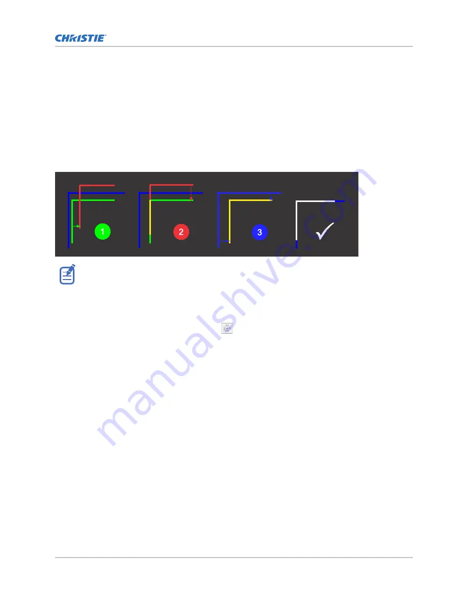
Adjusting the convergence is accomplished by aligning a red, green and blue sprite, which is displayed
at the four corners of the displayed image. For electronic convergence all three colors can be adjusted.
Always align the color components of the sprite to the inner most line color (for each axis). When
converged, the three colors should overlap to form white lines. Applying the sprite alignment settings
to the screen results in the three colors overlapping to form white lines throughout the image.
One or more poorly converged individual colors may appear adjacent to some or all of the lines.
If you wear glasses with corrective lenses when performing this adjustment, make sure you are viewing
the test pattern on a straight angle through the optical axis of your glasses and not from a tilted or
angled perspective. This avoids a prismatic effect that can appear to shift convergence when viewing at
an angle.
1. In the left navigation menu, select Image Settings > ILS File Setup.
2. Use the arrow to select an ILS file to store the ECC settings.
3. On the ILS File Setup page, select ECC.
Each corner of the screen displays three separate sprites, one for each primary color. The user
interface displays the Test Pattern controls.
4. Set the Screen Type to Flat or Scope.
This sets the test pattern and the location of the sprites on the screen. Each sprite appears as
the letter L.
5. Set the Sprite Color to Move and Show.
When first opening the ECC, all Show and all Move colors are selected, so all three sprites are
displayed and all three sprites are moved by the directional pad.
6. Select a Step Size to control the granularity of the steps from coarse (1/8 pixel per step) to
fine (1/64 pixel per step) when using the directional pad.
Sprites can be moved a maximum of 20 pixels.
7. Choose a corner by selecting the circle at a corner of the dashed rectangle.
The selected corner is indicated by a green circle. The X/Y pixel offset (from no correction)
displays in red, green, and blue text corresponding to each sprite.
8. Use the directional pad to move the sprites towards the center of the screen.
9. Adjust each sprite so they overlap to create a single white sprite.
In the example below, the red sprite (in image 1 below) was moved down and the blue sprite
(in image 1 below) was moved to the right so they overlap to create the single white sprite
(image 2 below).
Adjusting the image
CP2415-Xe Installation and Setup Guide
36
020-103584-02 Rev. 1 (09-2022)
Copyright
©
2022 Christie Digital Systems USA, Inc. All rights reserved.
If printed, please recycle this document after use.
Содержание CP2415-Xe
Страница 1: ...Installation and Setup Guide 020 103584 02 CP2415 Xe...
Страница 48: ......


