


CHOWEL / PATC-150A-EU
- 8 -
3-3-2. Air supply and Cooling water Requirements
Air supply source Max. supply pressure
: 6.5
㎏
f/
㎠
(
≒
6.37 bar)
Min. supply pressure
: 3.0
㎏
f/
㎠
(
≒
2.94 bar)
Cooling water source Max. supply pressure
: 3.0
㎏
f/
㎠
(
≒
2.94 bar)
Min. supply pressure
: 1.0
㎏
f/
㎠
(
≒
0.98 bar)
Cooling water temperature : lower than 30
℃
(80
℉
)
( at the water inlet )
Cooling water quantity
: 6
ℓ
/min (for only TR.)
Electric resistivity
: More than 5000
Ω
cm
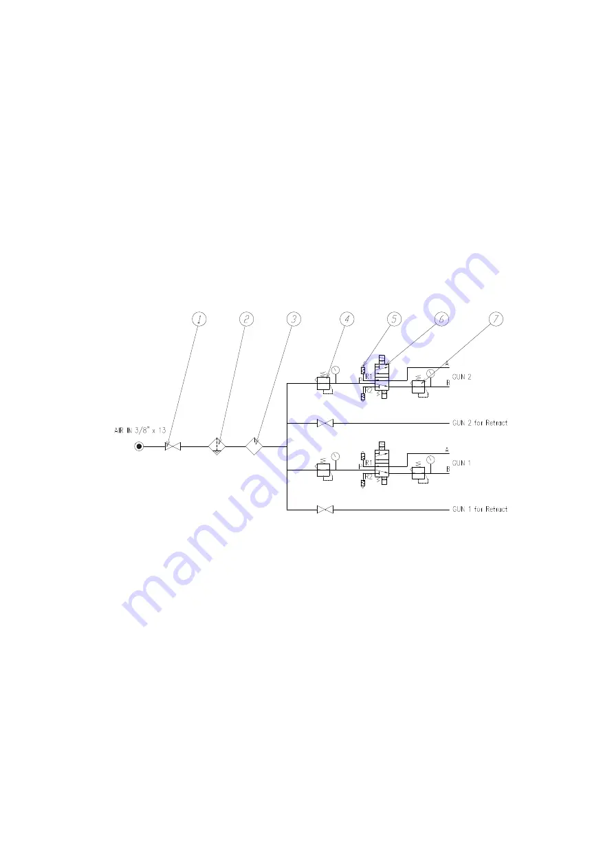
3-3-3
.
Air supply circuit diagram
※
Function of each part
①
Ball Valve( Check valve)
: main air line ON/OFF (1/2")
②
Air Filter
: Filtering particle and moisture from the air
③
Lubricator
: Lubrication of air supply circuit.
④
Regulator
: Regulate air pressure out of main air.
⑤
Silencer
: Reduces noise of air exhaust
⑥
Solenoid V/V
: Controls air supply direction
⑦
Space Regulator
: Regulate air pressure out of B port
Содержание PATC--150A-EU
Страница 20: ...CHOWEL PATC 150A EU 11 Pulsation 1 9 times...
Страница 65: ...CHOWEL PATC 150A EU 56 1 Weld program sheet...
Страница 67: ...CHOWEL PATC 150A EU 58 3 I O connection diagram...
Страница 68: ...CHOWEL PATC 150A EU 59 4 RC 05 wiring diagram...
Страница 69: ...CHOWEL PATC 150A EU 60 5 Outside view of PATC 150A EU...
Страница 70: ...CHOWEL PATC 150A EU 61 6 Outside view of TB 30...
Страница 71: ...CHOWEL PATC 150A EU 62 7 Outside view of RB 10...
Страница 72: ...CHOWEL PATC 150A EU 63 8 Electrical connection for step down T R and SCR...
Страница 73: ...CHOWEL PATC 150A EU 64 9 Connection diagram for Timer Box connector 10 Connection diagram for SCR Box connector...


