
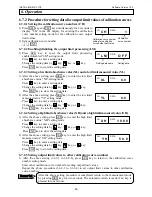


INST.No.INE-475-P1CE Software Version 1.00
-37-
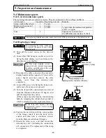
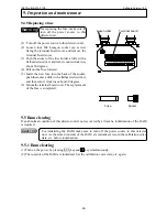
9.4.3 Replacing a motor
(1) Turn off the power source to this detector
unit.
(2) Loosen four M4 hexagon socket cap screws
fixing the data display cover and remove the
data display cover slightly.
(3) Disconnect the cable connector (26 pins) at
the display board and the connector (7 pins)
at the power board, and then remove the data
display cover from this detector unit
completely.
(4) Remove the motor connector (2 pins).
(5) Loosen the fixing screws (M3 pan screws) of
the motor band fixing the motor and remove
the motor by pulling the motor band upward
while pressing the motor.
(6) Make the motor unit stand as shown in the
figure and hold the sector lightly. Remove 4
pieces of M2 screws and separate the sector
from the motor.
(7) Make the new motor stand, too, and mount it
to the sector. Note that the sector has front
and back sides.
(8) Place the motor unit to make the top of the
motor touch the stopper of the motor
mounting base, cover the motor with the
motor band, and then fix the motor by
screwing the fixing screws of the motor
band.
(9) Connect the motor connector, and then
mount the data display cover (including the
connections of 2 connectors). The
replacement of the motor is completed.
For replacing the motor, make
sure to turn off the power source
to this detector unit.
As the data display cover is
connected with internal components
by cables, carefully remove the
cover not to scratch the cables.
Never scratch the optical filter
attached to the sector during the
replacement of the motor.
9. Inspection and maintenance
Warning
Sector
Motor
Caution
Caution
Motor connector (2 pins)
Motor band
Motor unit
Stopper of the motor
Display board connector (26 pins)
Data display cover
Power board
connector (7 pins)


