


INST.No.INE-475-P1CE Software Version 1.00
-19-
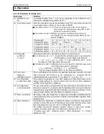
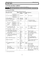
Setting data name
Description
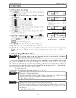
(12) Communications speed,
Parity, Data length, Stop bit
length, BCC enabled
/disabled
When this detector unit is connected with the operator
interface/display unit, skip these settings.
These are for communications with a personal computer, a
sequencer or other similar devices. Set them corresponding to a
master unit.
• Communications speed: Select 9600 or 19200bps.
• Parity: Select No, Even or Odd.
• Data length: The data length of the MODBUS RTU mode is fixed
to 8 bits. No need to select.
• Stop bit length: The stop bit length of the MODBUS RTU mode
is automatically set with the setting of the parity.
(EVEN or odd parity: 1 bit, No parity: 2 bits)
• BCC enabled/disabled: *This is not used with this detector unit.
(13) Sample
temperature
correction ON/OFF
When calibration curves change by sample temperatures, this
function enables to change the calibration curve to the other one by
measuring the sample temperature.
As the input of the sample temperature, a radiation thermometer or
a temperature/voltage converter with the output of 4 to 20mADC
can be used.
When the sample temperature correction is set to ON, the following
settings are required.
・
Correction input scaling L, Correction input
scaling H
These are used for scaling of 4 to 20mA correction input.
(14) Surface water ratio
computation
ON/OFF
For the computation of the moisture content of sands, etc., select
the surface water coefficient computation is enabled or disabled. Set it
to ON for enabling.
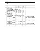
(15) Engineering
mode
Set
the
“weight
α
1” and “calibration constant” to processing mode 1
to processing mode 3.
(1) Weight
α
1: The 3-wavelength processing or 2-wavelength
processing can be switched by changing of the
setting of the weight
α
1.
When
α
1 is set to 0.5, the processing becomes the 3-wavelength
processing that is the ratio processing of three (3) wavelengths.
When
α
1 is set to 0 or 1, the processing becomes the
2-wavelength processing.
(
α
1: 1 - the ratio processing of
λ
1 and
λ
2,
α
1: 0 - the ratio
processing of
λ
2 and
λ
3)
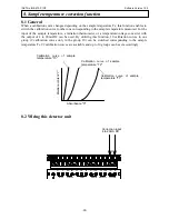
(2) Calibration constant K1: This is the value obtained in [6.5
Calibration] and has been stored
automatically.
6. Operation
Reference
·Please replace
α
1 to
α
2 and k1 to k2 in processing
mode2.
·Please replace
α
1 to
α
3 and k1 to k3 in processing
mode3.
Refer to [6.3.1-2) Functions of setting data


