


INST.No.INE-471-P1CE Software Version 1.00
-9-
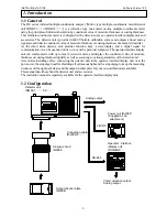
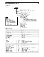
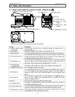
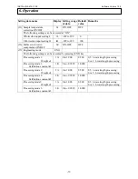
4.3.2 Relaying boxes not used
!
4. Connections
SERIES
IM
SERIES
IM
-V
+V
OUTPUT
DC 24V 2.1A
DC ON
DC LOW
V.ADJ
INPUT 50/60Hz
AC100-240V 1.3A
-V
+V
OUTPUT
DC 24V 2.1A
DC ON
DC LOW
V.ADJ
INPUT 50/60Hz
AC100-240V 1.3A
SERIES
IM
-V
+V
OUTPUT
DC 24V 2.1A
DC ON
DC LOW
V.ADJ
INPUT 50/60Hz
AC100-240V 1.3A
100-240V AC
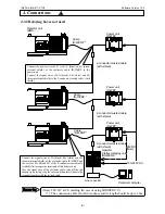
Connect the power wires of P+ (red), P- (blue), and G (green
external shield) of the exclusive cable IR-WERP to the
power unit.
Connect the signal wires of SA (black), SB (white) and SG
(brown internal shield) to the 2-conductor twisted cable (with
shield).
Connect the signal wires of SA (black), SB (white) and SG
(brown internal shield) of the exclusive cable IR-WERP and
the wires of SA, SB and SG of the 2-conductor twisted cable
(with shield) to respective terminals of this detector unit.
(For the signal wire of the exclusive cable, take off the rod
shaped tip on its top, strip the cover and then insert them to the
terminal together with the twisted cable.
Power unit
IR-WEP
Power unit
IR-WEP
Power unit
IR-WEP
Line converter
Detector unit
IRMA
Cable
IR-WERP *
2-conductor twisted cable
(with shield)
Cable
IR-WERP *
Cable
IR-WERP *
Operator
interface/display unit
IRGMEG2
Personal computer
2-conductor twisted cable
(with shield)
2-conductor twisted cable
(with shield)
24V DC
(Note)
R e m a r k s
(Note): 24V DC at CE marking (In case of using IRGMEG2 V)
(*): The connection cable should be indoors and its length should be up to 30m.


