


REAR AXLE D IFFER EN TIA L CARRIER 4-31
Shim Identification
Shim
Thickness
Notches
I.D.
O.D.
.040
0
0
.042
4
1
.044
4
2
.046
4
3
.048
4
4
.050
5
0
.052
5
1
.054
5
2
.056
5
3
.058
5
4
.060
6
0
.062
6
1
.064
0
2
.066
0
3
.068
0
4
.070
1
0
.072
1
1
.074
1
2
.076
1
3
.078
1
4
.080
2
0
.082
2
1
.084
2
2
.086
2
3
.088
2
4
.090
3
0
.092
3
1
.094
3
2
.096
3
3
.098
3
4
.100
4
0
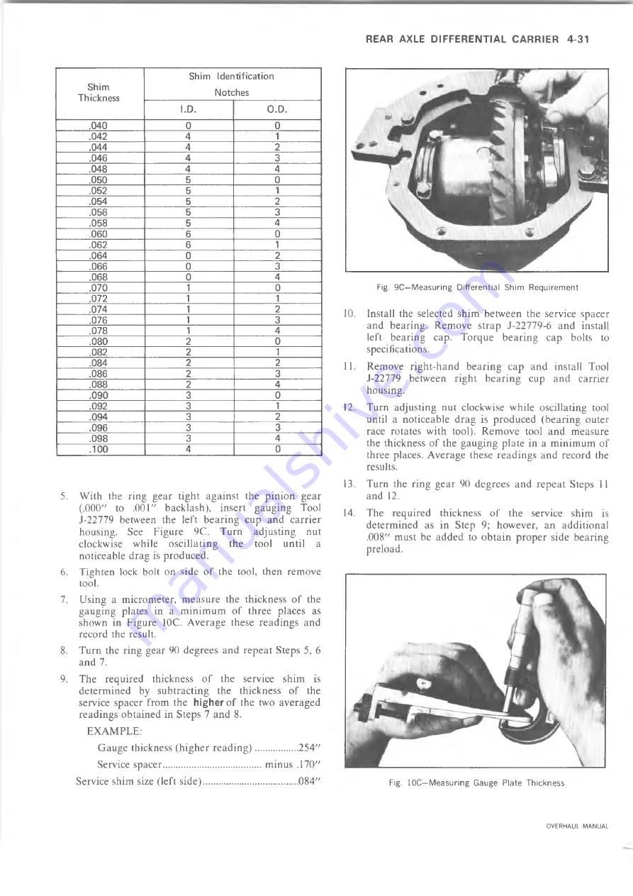
5. With the ring gear tight against the pinion gear
(.000" to .001" backlash), insert gauging Tool
J-22779 between the left bearing cup and carrier
housing. See Figure 9C. Turn adjusting nut
clockwise while oscillating the tool until a
noticeable drag is produced.
6. Tighten lock bolt on side o f the tool, then remove
tool.
7. Using a micrometer, measure the thickness of the
gauging plates in a minimum of three places as
shown in Figure 10C. Average these readings and
record the result.
8. Turn the ring gear 90 degrees and repeat Steps 5, 6
and 7.
9. The required thickness of the service shim is
determined by subtracting the thickness of the
service spacer from the
higher
of the two averaged
readings obtained in Steps 7 and 8.
EXAMPLE:
Gauge thickness (higher reading).................254"
Service spacer....................................... minus .170"
Service shim size (left side)...................................... 084"
Fig. 9C—M easuring D iffe re n tia l Shim R equirem ent
10. Install the selected shim between the service spacer
and bearing. Remove strap J-22779-6 and install
left bearing cap. Torque bearing cap bolts to
specifications.
11. Remove right-hand bearing cap and install Tool
J-22779 between right bearing cup and carrier
housing.
12. Turn adjusting nut clockwise while oscillating tool
until a noticeable drag is produced (bearing outer
race rotates with tool). Remove tool and measure
the thickness of the gauging plate in a minimum of
three places. Average these readings and record the
results.
13. Turn the ring gear 90 degrees and repeat Steps 11
and 12.
14. The required thickness of the service shim is
determined as in Step 9; however, an additional
.008" must be added to obtain proper side bearing
preload.
Fig. 10C—M easuring Gauge Plate Thickness
OVERHAUL MANUAL
Содержание 10 series 1973
Страница 1: ......
Страница 3: ...r...
Страница 5: ......
Страница 21: ......
Страница 31: ......
Страница 34: ...REAR AXLE DIFFERENTIAL CARRIER 4 3 OVERHAUL MANUAL...
Страница 85: ...4 54 REAR AXLE DIFFERENTIAL CARRIER OVERHAUL MANUAL...
Страница 93: ...4 62 REAR AXLE DIFFERENTIAL CARRIER OVERHAUL MANUAL...
Страница 103: ...V...
Страница 141: ...I...
Страница 144: ...ENGINE 6 3 OIL PRESSURE SENDING UNIT Fig 1 In Line Engine Lubrication OVERHAUL MANUAL...
Страница 145: ...6 4 ENGINE FUEL PUMP PUSH ROD OILING OIL FILTER AND BY PASS VALVE Fig 2 Sm all V8 Engine Lubrication OVERHAUL MANUAL...
Страница 179: ......
Страница 185: ...6M 6 CARBURETORS Fig M6 Monojet See Fig M7 for legend...
Страница 219: ...L...
Страница 247: ...7 M 28 CLUTCHES AND MANUAL TRANSMISSIONS Fig 19X Loading Countergear Bearings Fig 20X Loading Mainshaft Pilot Bearings...
Страница 289: ...7M 70 CLUTCHES AND MANUAL TRANSMISSIONS Fig 13F Transfer Case Exploded View OVERHAUL MANUAL...
Страница 352: ...AUTOMATIC TRANSMISSION 7A 49 Fig 85M Planetary Gear Train Exploded View OVERHAUL MANUAL...
Страница 363: ...7A 60 AUTOMATIC TRANSMISSION Fig IT S ide Cross Section Typical OVERHAUL MANUAL...
Страница 457: ......
Страница 459: ......
Страница 522: ......