Instructions for installation and use. Reproduction prohibited. 07/ 2010 version 2.0 TAM
19
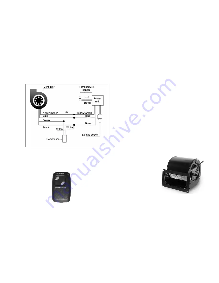
Electrical diagram of ventilator connection
-
The remote control.
The remote control covers all ventilator functions. It is supplied with an A23
12V battery. To synchronise and/or modify its transmission code, first of all
take out the DIP switches then push well in, holding down the button inside
the power unit, and at the same time press the remote control’s AUTO/MAN
key for 2 seconds.
-Operation.
By pushing the AUTO/MAN key you go from one function to the next, with
the following characteristics: in AUTO or automatic mode, the device puts out
an intermittent sound signal to confirm the selected function; when the insert
is hot, the ventilator starts up in autonomous mode, and its range may be
selected by the SPEED key; in MANUAL mode, the device emits a
continuous sound signal. Three different air ranges can be selected by
pressing the SPEED 1-2-3 key: to confirm your choice, the device emits a
single-beep sound signal for the first speed, a two-beep signal for the second
speed and a three-beep signal for the third speed. To interrupt or stop
ventilation, use the AUTO function with the AUTO/MAN key. Remember that
complete stop of ventilation only occurs when the insert body is cold: the
purpose of ventilation is also to ensure that the internal parts of the insert
itself do not overheat. Finally – and this is very important –
never
disconnect the plug from the electrical socket while the insert is in
operation
, to avoid damaging the appliance through overheating.
Centrifugal ventilator positioned beneath the monoblock.
Technical data
:
230 V
50/60 Hz
CL. F
2.5 µF 400V TH.PROT.
0.47 A - 60 W
Range 480 m3/h


