RSR-000885-000 (6)
Page
13
of
20
Caution:
DO NOT
clean the lens inside the hand piece. Doing so may damage the lens during laser emission.
5.1.1.
Cleaning the System
Step 1.
Before cleaning the console, turn off the laser system and unplug the power cord from the wall outlet.
Step 2.
The exterior surfaces on the unit and treatment heads can be cleaned by wiping with a soft, non-fibrous wipe (e.g.,
Kimwipes
®
) moistened with isopropyl alcohol solution.
•
Ensure the solution is only 70% alcohol. Solutions of more than 70% alcohol can cause product damage.
•
Avoid using soiled or gritty cloths.
Step 3.
After cleaning, ensure that all cleansers have been removed and the parts are dry before use.
5.1.2.
Disassembly and Cleaning of the Massage Attachments
Caution:
Always keep the lenses and all optics within the treatment head attachments clean and free of dust and debris. Use of
contaminated optics may lead excessive thermal buildup and damage the equipment.
On-contact massage attachments, including the Large Massage Ball and Rolling Pin, may accumulate particulates within the housings
holding the optics. To reduce damage and potential harm, these attachments must be disassembled and cleaned between treatments.
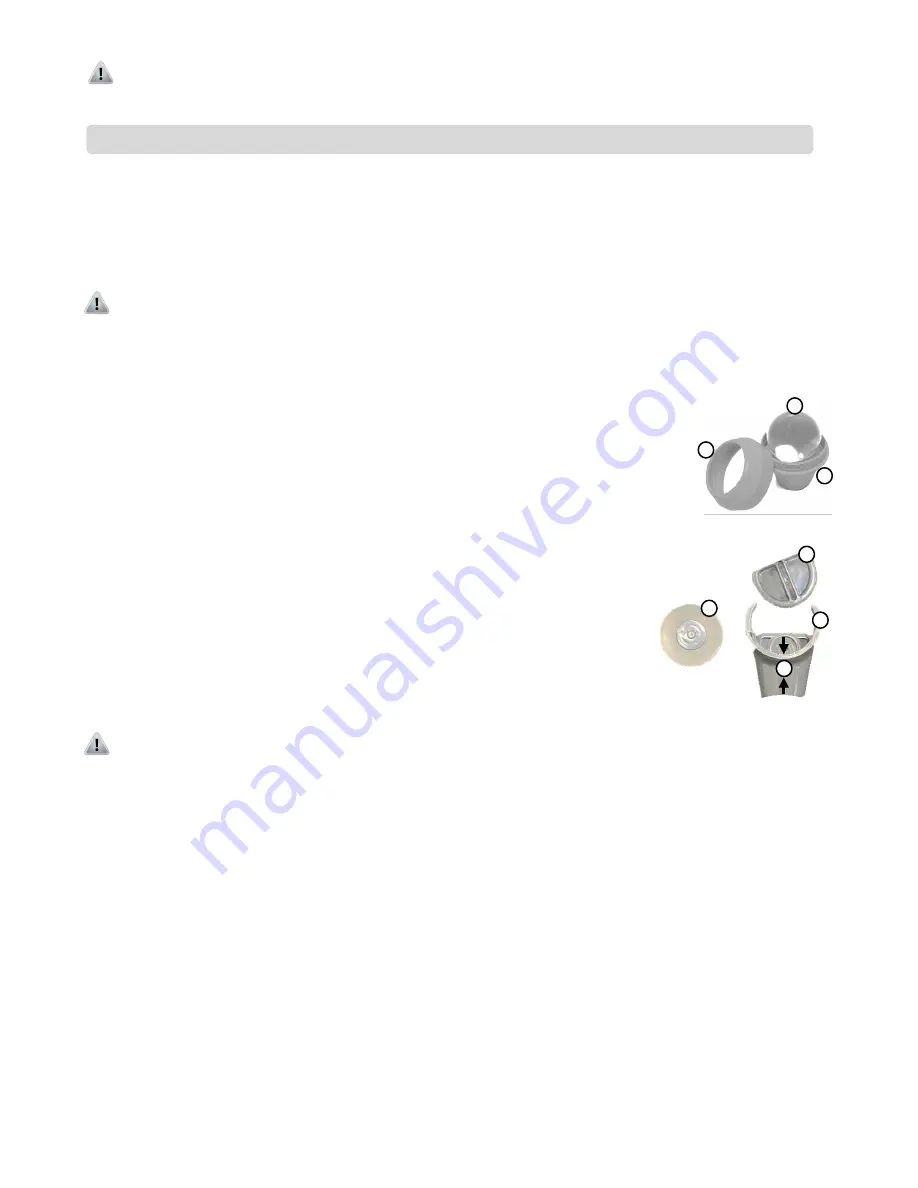
Refer to the diagrams and instructions below for proper cleaning techniques.
5.1.2.1. Large Massage Ball (Figure 25)
Step 1.
Remove the elastic band from the large massage ball treatment head and unscrew the top housing
Step 2.
Remove the glass ball for cleaning. Use a soft, non-fibrous wipe moistened with 70% isopropyl
alcohol solution. Do not wipe with a dry cloth; always dampen the cloth before wiping.
Step 3.
For other hard to reach surfaces within the bottom housing, canned air may be used to remove
dust and debris.
Step 4.
Ensure that all cleansers have evaporated and the parts are dry before re-assembly and use.
Reassemble treatment head by inserting the massage ball and screwing the top housing securely
on the treatment head while ensuring not to overtighten the top housing.
5.1.2.2. Rolling Pin (Figure 26)
Step 1.
Pinch and turn the side lock counterclockwise to unlock it and pull it away from the housing.
Step 2.
Carefully slide the rolling pin optic out. Use a soft, non-fibrous wipe moistened with 70%
isopropyl alcohol solution. Do not wipe with a dry cloth; always dampen the cloth before
wiping.
Step 3.
For other hard to reach surfaces within the bottom housing, canned air may be used to
remove dust and debris.
Step 4.
Clean the top side of the concave window within the bottom housing by ensuring there is
no debris on the lens. Flip it over and clean the bottom side of the window where the light
enters from the hand piece.
Step 5.
Ensure that all cleansers have evaporated and the parts are dry before re-assembly and
use. Reassemble treatment head by inserting the Rolling Pin and side lock and then
twisting the side lock clockwise until it locks.
Caution:
Mishandling of the attachment or its components, may damage the optics and plastic housings. If significant damage has
occurred, discontinue use. Ensure the optics are clean and free of debris that could cause damage over continued use.
There will be minor scratches resulting from normal use. These will not affect the efficacy of the laser treatment. shows a massage ball
treatment head with a ball that has some minor scratches. If scratches in the large massage ball become significant producing a cloudy
appearance, then the massage ball treatment head can be replaced.
5.2. Before You Call—Troubleshooting
If you are having a problem with your laser system, please check the list below of common conditions that can occur that you may be able to
resolve without having to contact Customer Care.
The laser system will display error messages to caution the operator to fault conditions. If any of the following errors occur, the laser system
will remain in
Standby
mode, or return to
Standby
mode, produce an audible warning and display the related message describing the fault
condition. The following are examples of these fault conditions:
•
Optical fiber is not inserted,
•
Remote interlock is removed,
•
Finger switch is depressed.
To proceed, correct the error and press the
exit
button.
The system continuously monitors the output current of the diodes to ensure they are within the factory calibration settings. If it is detected
that the electrical current levels exceed the upper or lower limits that would result in power levels outside of the ±20% thresholds, the laser
will stop emission and require system reset.
•
When the laser pulse rate is CW, the laser output power is the same as the power setting on the display within operating tolerances.
•
When the laser pulse rate is not CW (e.g. 10 Hz), the average output power is 50% of the power setting on the display, within
operating tolerances.
The laser system will not enter or remain in
Emission
if the laser system is overheating. If temperatures exceed safety limits:
•
There will be an audible warning.
•
There will be an error message: Laser temperature is out of range.
Note:
The laser system uses solid-state laser technology. It is important to keep the unit and accessories free from dust.
Figure 26
1
2
3
4
1
2
3
Figure 25
Содержание LIGHTFORCE XLi
Страница 251: ...RSR 000885 000 6 Pagina 7 di 22 ...

