


Chapter VII Performance feature test
86
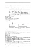
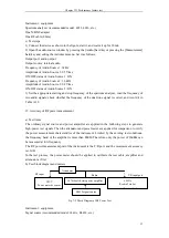
source, and the output power accuracy refers to the difference between the actual output power
and set value of the signal source.
The output power range and accuracy of the signal source of this instrument are shown in the
following table.
Table 7-2 Output Power Range and Accuracy of Signal Source
Test Port
Range
of
output
power
Accuracy
RF
source 1
SWR
-5dBm ~ -65dBm
2dB
T/R
-50dBm ~ -125dBm
-50dBm ~ -100dBm,
2dB
-100dBm ~ -125dBm,
5dB
ANT
-5dBm ~ -100dBm
2dB
RF
source 2
ANT
0dBm ~ -100dBm
2dB
b) Test block diagram and meters
Instrument / equipment:
Receiver (recommended model: 3923 and FSMR50)
Sensor(recommended model: 8710 and NRP-Z37)
One N/BNCadapter
One RF cable (80cm)
c) Test steps
1) As shown in the figure, connect the test instrument, turn on it and warm it up for 30min.
2) Set the receiver into the RF turning level measurement mode, and connect the sensor of the
receiver to the SWR port of the tested device.
3) Open the RF source window by pressing the [Receiver] hard key or pressing the [Measurement]
hard key and setting the instrument menu. Set it as follows.
Output port: SWR
RF Source 1: ON
The modulation window must not be opened.
4) Set the signal frequency and power of RF Source 1 of the test instrument according to Table
A.3, and record the test result into the corresponding part of Table A.3.
5) Connect the sensor of the receiver to the T/R port of the instrument, and change the output port
of RF Source 1 into the T/R port.
6) Set the signal frequency and power of RF Source 1 of the test instrument according to Table
A.3, and record the test result into the corresponding part of Table A.3.
7) Connect the sensor of the receiver to the ANT port of the instrument, and change the output
port of RF Source 1 into the ANT port.
8) Set the signal frequency and power of RF Source 1 of the test instrument according to Table
A.3, and record the test result into the corresponding part of Table A.3.
SWR/T/R/ANT port output
3923
Receiver
4992A
Rradio Test Set
RF input
Fig. 7-2 Block Diagram of Output Power Range, Accuracy, Spectrum Purity and Modulation Test
of RF Source
Содержание 4992A
Страница 1: ...I 4992A Radio Test Set User Manual China Electronics Technology Instruments Co Ltd...
Страница 2: ......
Страница 5: ......
Страница 6: ......
Страница 7: ......
Страница 23: ...Article I Handling Instructions 11 Article I Handling Instructions...
Страница 93: ...81 Article II Technical Specifications...
Страница 132: ...Article III Maintenance Instructions 120 Article III Maintenance Instructions...


