


Chapter IV Operation Guidance
31
Section 2 Operation Guidance for RF Receiver Function
This part describes some operations of 4992A Radio Test Set for RF signal reception and
measurement.
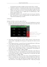
1.RF power
The RF power measurement of 4992A is designed for the RF T/R port only, and the
broadband signal power of RF 20-43dBm can be measured.
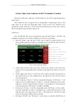
Window opening: open the RF meter window by pressing the [Measurement] hard key and
setting the instrument menu, and click the RF power in the touch screen, or click the [RF
Power] soft key in the right side to enable the RF power function. Press the [Full Screen]
hard key in the lower part of the screen to maximize the window, as shown in Fig. 4-4.
Fig. 4-4RF Power Measurement Window
Menu calling: open and select the RF meter window, and the corresponding menu will be
displayed in the right side of the window, as shown in Fig. 4-4.
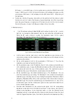
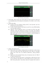
Display of measurement results:
Unit selection: click the [RF Power Unit] soft key in the right side of the touch screen
and select the output unit: dBm, W, μV and dBμV.
Average setting: the real-time broadband power is measured in RF power measurement.
Therefore, the averaging of measurement results can be set according to the stability
requirements. In particular, when the tested signal is the FM signal of low modulation
rate, measurement results will change constantly. In this case, the user can set the
averaging of measurement results to stabilize the display effects in the following method:
click “Average” in the window or the [Average] soft key in the right side of the touch
screen, open “Average”, click the [Averaging Times] soft key in the right side of the
touch screen, and the measurement result will be displayed after averaging according to
the set times.
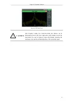
Setting of compensation frequency of frequency response: the user should enter the
frequency according to the current test signal, and the frequency response will be
compensated automatically.
Alarm setting: judge whether the measurement result conforms to the requirements. If it is
Average
ON/OFF
Setting of frequency
Selection of RF power
unit
Selection of signal
strength unit
Alarm device
Average
frequency
RF power ON OFF
Содержание 4992A
Страница 1: ...I 4992A Radio Test Set User Manual China Electronics Technology Instruments Co Ltd...
Страница 2: ......
Страница 5: ......
Страница 6: ......
Страница 7: ......
Страница 23: ...Article I Handling Instructions 11 Article I Handling Instructions...
Страница 93: ...81 Article II Technical Specifications...
Страница 132: ...Article III Maintenance Instructions 120 Article III Maintenance Instructions...


