


48
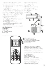
Remove the maintenance panel protective covers of the indoor and
outdoor units. Loosen the terminal strip screws and properly connect
the cores of the inter-unit electrical cable and power cable to the
terminals (for some models the indoor units can be shipped with the
power cable and plug already connected).
Connect the earthing wire with screws to the threaded holes
located separately on the maintenance panels. Observe the proper
connection of the wires. Securely tighten the terminal strip screws
to prevent their loosening. Ensure that the connected wires do not
move by pulling on them. Fasten the inter-unit electrical cable in the
provided clamps. Reinstall the protective covers on the indoor and
outdoor unit maintenance panels.
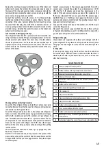
Tube Insulation and Wrapping with Tape
The refrigerant tubes should be provided with heat insulation. The
refrigerant tube connection fittings, including the outdoor unit valves
should also be heat-insulated. The drain tube, if routed indoors,
should be provided with heat insulation. Use the supplied tape to
tightly wrap the refrigerant tubes, drain tube (hose) and inter-unit
electrical cable. The drain tube (hose) should be located at the very
bottom of the bundle.
Checkup and Vacuum Testing Procedures
Ensure that the refrigerant tubes and electrical cables are properly
connected. Remove the protective caps from the gas and liquid valves
in the outdoor unit refrigerant tubes.
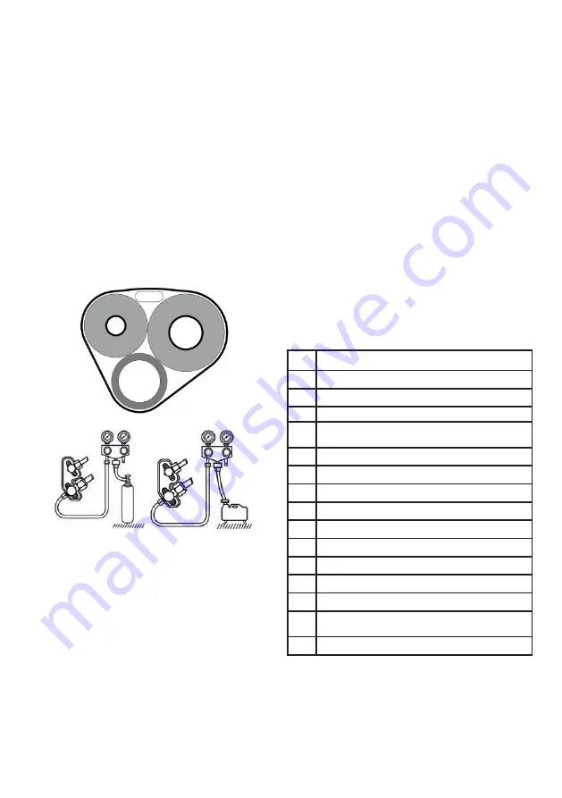
Ensure that the gas and liquid valves in the outdoor unit refrigerant
tubes are closed. Connect the pressure gage manifold and nitrogen
bottle to the maintenance port of the outdoor unit gas refrigerant
tube. The bottle should be connected via a pressure reducer. The use
of compressed air is not allowed because of the presence of moisture.
Pressurize the system with nitrogen to 4.15 MPa. Keep the nitrogen
bottle with the valve facing up to prevent liquid nitrogen from getting
into the system.
Check all pipeline connections for leaks, e.g. by applying soap suds.
Repair any revealed leaks.
Wait for 10-15 minutes and check the pressure in the system. If the
pressure drops, inspect the system to find the reason. Disconnect the
nitrogen bottle from the pressure gage manifold. Pump the nitrogen
out of the system.
Connect a vacuum pump to the pressure gage manifold. Turn on the
vacuum pump. Evacuate the system to an underpressure of –0.101
MPa. Wait for 5-10 minutes and check the underpressure in the
system. If the underpressure decreases inspect the system to find
that cause. Disconnect the vacuum pump from the pressure gage
manifold. Make sure that the pressure gage manifold and vacuum
pump are used properly, carefully read the operating manuals of each
device and instrument before use.
Fully open the refrigerant valves of the outdoor unit, first the liquid
valve, then the gas valve.
Disconnect the pressure gage manifold from the outdoor unit gas
refrigerant tube maintenance port. Install the protective caps on the
gas and liquid refrigerant valves of the outdoor unit.
Refrigerant Charging
These models are supplied with outdoor units charged with R32
grade refrigerants. The systems do not require additional refrigerant
charging if the tube length do not exceed the limitations specified
above.
Test Operation
Turn on AC power supply. Using the RC unit turn the AC on and check
its functionality in different modes. It should be noted that the AC
efficiency test should be performed after at least 15 to 20 minutes
after the first startup.
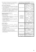
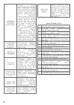
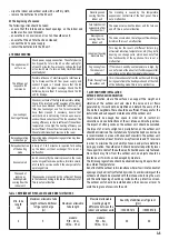
TABLE OF FAULT CODES
E1
Indoor air temperature sensor failure
E2
Outdoor unit heat exchanger temperature sensor failure
E3
Indoor unit heat exchanger temperature sensor failure
E4
Indoor unit fan motor failure
E5
Malfunction in the communication line between the outdoor and
indoor units
F0
Outdoor unit fan motor failure
F1
IPM module ( Intelligent Power Module) error
F2
PFC module error
F3
Compressor malfunction
F4
Compressor discharge line temperature sensor failure
F5
Compressor overload safety tripped
F6
Outdoor air temperature sensor failure
F7
Over- or undervoltage protection tripped
F8
Outdoor unit module communication line failure
F9
EEPROM (Electrically Erasable Programmable Read Only Memory)
module failure
FA
Suction line temperature sensor failure (4-way valve malfunction)


